tow BMW M3 COUPE 2008 E92 User Guide
[x] Cancel search | Manufacturer: BMW, Model Year: 2008, Model line: M3 COUPE, Model: BMW M3 COUPE 2008 E92Pages: 172, PDF Size: 5.29 MB
Page 83 of 172
Reference
At a glance
Controls
Driving tips
Mobility
81
Automatic climate control
Comfortable interior climate
AUTO program7 offers the ideal air distribution
and air flow rate for almost all conditions, refer
to AUTO program below. All you need to do is
select an interior temperature which is comfort-
able for you.
The following sections inform you in detail
about how to adjust the settings.
Most settings are stored for the remote control
currently in use, refer also to Personal Profile
settings on page18.
Adjusting air distribution manually
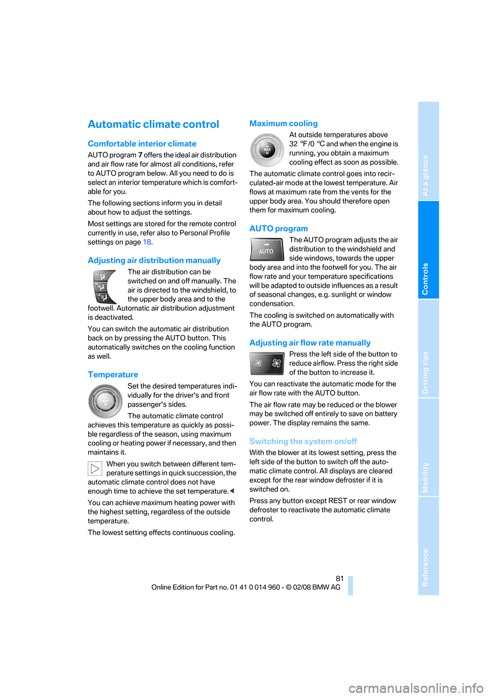
The air distribution can be
switched on and off manually. The
air is directed to the windshield, to
the upper body area and to the
footwell. Automatic air distribution adjustment
is deactivated.
You can switch the automatic air distribution
back on by pressing the AUTO button. This
automatically switches on the cooling function
as well.
Temperature
Set the desired temperatures indi-
vidually for the driver's and front
passenger's sides.
The automatic climate control
achieves this temperature as quickly as possi-
ble regardless of the season, using maximum
cooling or heating power if necessary, and then
maintains it.
When you switch between different tem-
perature settings in quick succession, the
automatic climate control does not have
enough time to achieve the set temperature.<
You can achieve maximum heating power with
the highest setting, regardless of the outside
temperature.
The lowest setting effects continuous cooling.
Maximum cooling
At outside temperatures above
327/06 and when the engine is
running, you obtain a maximum
cooling effect as soon as possible.
The automatic climate control goes into recir-
culated-air mode at the lowest temperature. Air
flows at maximum rate from the vents for the
upper body area. You should therefore open
them for maximum cooling.
AUTO program
The AUTO program adjusts the air
distribution to the windshield and
side windows, towards the upper
body area and into the footwell for you. The air
flow rate and your temperature specifications
will be adapted to outside influences as a result
of seasonal changes, e.g. sunlight or window
condensation.
The cooling is switched on automatically with
the AUTO program.
Adjusting air flow rate manually
Press the left side of the button to
reduce airflow. Press the right side
of the button to increase it.
You can reactivate the automatic mode for the
air flow rate with the AUTO button.
The air flow rate may be reduced or the blower
may be switched off entirely to save on battery
power. The display remains the same.
Switching the system on/off
With the blower at its lowest setting, press the
left side of the button to switch off the auto-
matic climate control. All displays are cleared
except for the rear window defroster if it is
switched on.
Press any button except REST or rear window
defroster to reactivate the automatic climate
control.
Page 85 of 172
Reference
At a glance
Controls
Driving tips
Mobility
83
Ventilation
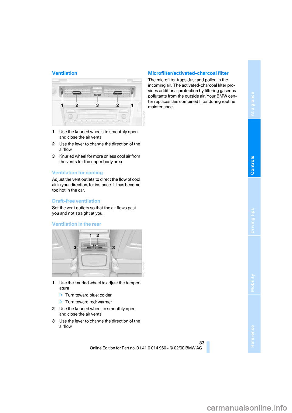
1Use the knurled wheels to smoothly open
and close the air vents
2Use the lever to change the direction of the
airflow
3Knurled wheel for more or less cool air from
the vents for the upper body area
Ventilation for cooling
Adjust the vent outlets to direct the flow of cool
air in your direction, for instance if it has become
too hot in the car.
Draft-free ventilation
Set the vent outlets so that the air flows past
you and not straight at you.
Ventilation in the rear
1Use the knurled wheel to adjust the temper-
ature
>Turn toward blue: colder
>Turn toward red: warmer
2Use the knurled wheel to smoothly open
and close the air vents
3Use the lever to change the direction of the
airflow
Microfilter/activated-charcoal filter
The microfilter traps dust and pollen in the
incoming air. The activated-charcoal filter pro-
vides additional protection by filtering gaseous
pollutants from the outside air. Your BMW cen-
ter replaces this combined filter during routine
maintenance.
Page 90 of 172
Practical interior accessories
88
LED hand lamp
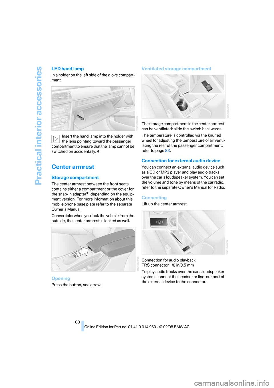
In a holder on the left side of the glove compart-
ment.
Insert the hand lamp into the holder with
the lens pointing toward the passenger
compartment to ensure that the lamp cannot be
switched on accidentally.<
Center armrest
Storage compartment
The center armrest between the front seats
contains either a compartment or the cover for
the snap-in adapter
*, depending on the equip-
ment version. For more information about this
mobile phone base plate refer to the separate
Owner's Manual.
Convertible: when you lock the vehicle from the
outside, the center armrest is locked as well.
Opening
Press the button, see arrow.
Ventilated storage compartment
The storage compartment in the center armrest
can be ventilated: slide the switch backwards.
The temperature is controlled via the knurled
wheel for adjusting the temperature of air venti-
lating the rear of the passenger compartment,
refer to page83.
Connection for external audio device
You can connect an external audio device such
as a CD or MP3 player and play audio tracks
over the car's loudspeaker system. You can set
the volume and tone by means of the car radio,
refer to the separate Owner's Manual for Radio.
Connecting
Lift up the center armrest.
Connection for audio playback:
TRS connector 1/8 in/3.5 mm
To play audio tracks over the car's loudspeaker
system, connect the headset or line-out port of
the external device to the connector.
Page 95 of 172
Reference
At a glance
Controls
Driving tips
Mobility
93
Convertible
Depending on your vehicle's equipment, the
following storage spaces can be found in the
cargo bay:
>Storage compartment on the left side of the
cargo bay. To open turn handle by 90°
>Net
* for securing smaller objects, to be
attached to the fixtures on the floor panel
>Rubber band
* to be attached to the lateral
lashing eyes
>Stowage compartment under the floor
panel
Folding up the floor panel
Do not exceed the maximum permissible
load of 55 lbs/25 kg for the storage com-
partment under the floor panel, otherwise dam-
age could result.<
Coupe
Press the floor panel up and secure it with the
catch.
Convertible
To lift, grab hold of the floor panel at the open-
ing at the rear of the panel.
Lashing eyes
You will find lashing eyelets in the cargo bay for
securing luggage items with nets or tensioning
straps, refer to page101.
Coupe: ski bag*
The ski bag is designed for safe, clean transport
of up to 4 pairs of standard skis or up to
2snowboards.
With the ski bag you can stow skis with a length
of up to 6ft 10in/2.10m. When skis of 6ft 10in/
2.10 m length are loaded, the overall capacity of
the ski bag is reduced due to its tapered design.
Loading
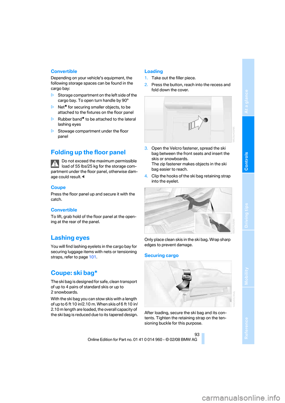
1.Take out the filler piece.
2.Press the button, reach into the recess and
fold down the cover.
3.Open the Velcro fastener, spread the ski
bag between the front seats and insert the
skis or snowboards.
The zip fastener makes objects in the ski
bag easier to reach.
4.Clip the hooks of the ski bag retaining strap
into the eyelet.
Only place clean skis in the ski bag. Wrap sharp
edges to prevent damage.
Securing cargo
After loading, secure the ski bag and its con-
tents. Tighten the retaining strap on the ten-
sioning buckle for this purpose.
Page 96 of 172
Practical interior accessories
94 Secure the ski bag in the manner
described, otherwise it could endanger
the car's occupants, e.g. in case of heavy brak-
ing or sudden swerving.<
To store the ski bag, perform the steps
described for loading in reverse order.
Removing the ski bag
The ski bag can be completely removed, e.g. for
faster drying or to allow you to use other inserts.
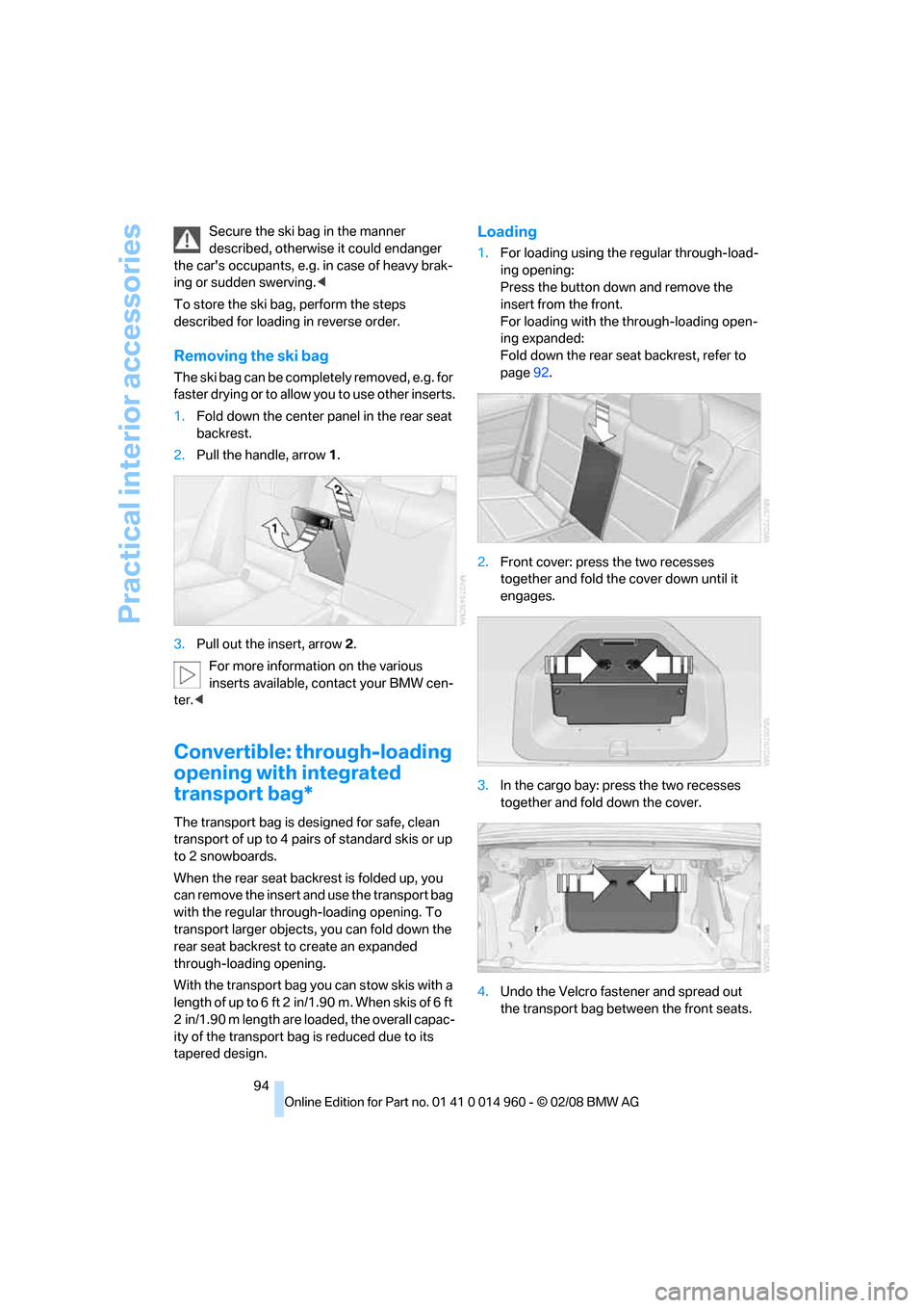
1.Fold down the center panel in the rear seat
backrest.
2.Pull the handle, arrow1.
3.Pull out the insert, arrow 2.
For more information on the various
inserts available, contact your BMW cen-
ter.<
Convertible: through-loading
opening with integrated
transport bag*
The transport bag is designed for safe, clean
transport of up to 4 pairs of standard skis or up
to 2 snowboards.
When the rear seat backrest is folded up, you
can remove the insert and use the transport bag
with the regular through-loading opening. To
transport larger objects, you can fold down the
rear seat backrest to create an expanded
through-loading opening.
With the transport bag you can stow skis with a
length of up to 6 ft 2 in/1.90 m. When skis of 6 ft
2 in/1.90 m length are loaded, the overall capac-
ity of the transport bag is reduced due to its
tapered design.
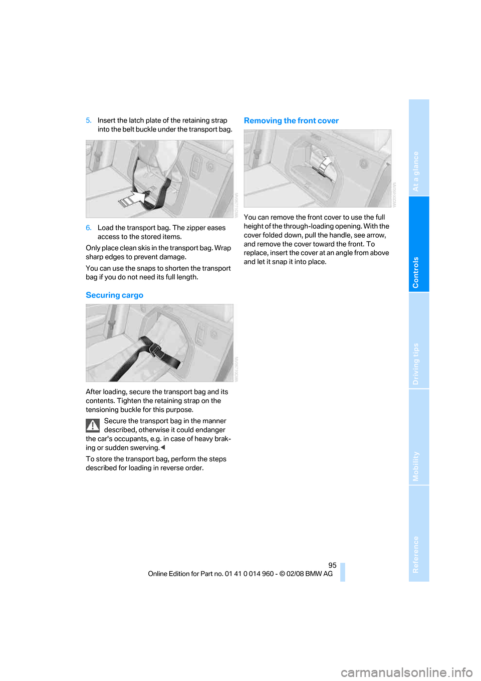
Loading
1.For loading using the regular through-load-
ing opening:
Press the button down and remove the
insert from the front.
For loading with the through-loading open-
ing expanded:
Fold down the rear seat backrest, refer to
page92.
2.Front cover: press the two recesses
together and fold the cover down until it
engages.
3.In the cargo bay: press the two recesses
together and fold down the cover.
4.Undo the Velcro fastener and spread out
the transport bag between the front seats.
Page 97 of 172
Reference
At a glance
Controls
Driving tips
Mobility
95
5.Insert the latch plate of the retaining strap
into the belt buckle under the transport bag.
6.Load the transport bag. The zipper eases
access to the stored items.
Only place clean skis in the transport bag. Wrap
sharp edges to prevent damage.
You can use the snaps to shorten the transport
bag if you do not need its full length.
Securing cargo
After loading, secure the transport bag and its
contents. Tighten the retaining strap on the
tensioning buckle for this purpose.
Secure the transport bag in the manner
described, otherwise it could endanger
the car's occupants, e.g. in case of heavy brak-
ing or sudden swerving.<
To store the transport bag, perform the steps
described for loading in reverse order.
Removing the front cover
You can remove the front cover to use the full
height of the through-loading opening. With the
cover folded down, pull the handle, see arrow,
and remove the cover toward the front. To
replace, insert the cover at an angle from above
and let it snap it into place.
Page 102 of 172
Things to remember when driving
100 during brake applications to clean the rotors is
not reached.
This can also lead to a permanent loss in ride
comfort and to squealing noises during braking.
A loss in comfort can also be caused by
extended braking with little pressure on the
pedal.
Should corrosion form on the brake rotors, the
brakes will tend to respond with a pulsating
effect that even extended application will fail to
cure.
For information on brake system technology,
refer to Compound brake on page103.
When the vehicle is parked
Condensation forms while the automatic cli-
mate control is in operation, and then exits
under the vehicle. Traces of condensed water
under the vehicle are therefore normal.
Cargo loading
To avoid loading the tires beyond their
approved carrying capacity, never over-
load the vehicle. Overloading can lead to over-
heating and increases the rate at which damage
develops inside the tires. This can ultimately
result in a sudden blow-out.<
Make sure that no liquids are spilled or
leak from their containers in the cargo
bay, as this could result in damage to the vehi-
cle.<
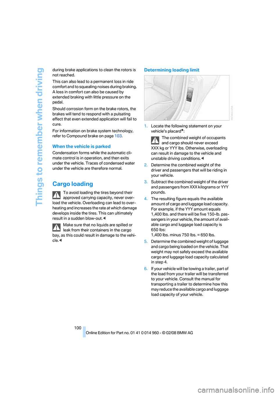
Determining loading limit
1.Locate the following statement on your
vehicle's placard
*:
The combined weight of occupants
and cargo should never exceed
XXX kg or YYY lbs. Otherwise, overloading
can result in damage to the vehicle and
unstable driving conditions.<
2.Determine the combined weight of the
driver and passengers that will be riding in
your vehicle.
3.Subtract the combined weight of the driver
and passengers from XXX kilograms or YYY
pounds.
4.The resulting figure equals the available
amount of cargo and luggage load capacity.
For example, if the YYY amount equals
1,400 lbs. and there will be five 150-lb. pas-
sengers in your vehicle, the amount of avail-
able cargo and luggage load capacity is
650 lbs:
1,400 lbs. minus 750 lbs. = 650 lbs.
5.Determine the combined weight of luggage
and cargo being loaded on the vehicle. That
weight may not safely exceed the available
cargo and luggage load capacity calculated
in step 4.
6.If your vehicle will be towing a trailer, part of
the load from your trailer will be transferred
to your vehicle. Consult the manual for
transporting a trailer to determine how this
may reduce the available cargo and luggage
load capacity of your vehicle.
Page 103 of 172
Reference
At a glance
Controls
Driving tips
Mobility
101
Load
The permissible load is the total of the weight of
occupants and cargo/luggage. The greater the
weight of the occupants, the less cargo/lug-
gage can be transported.
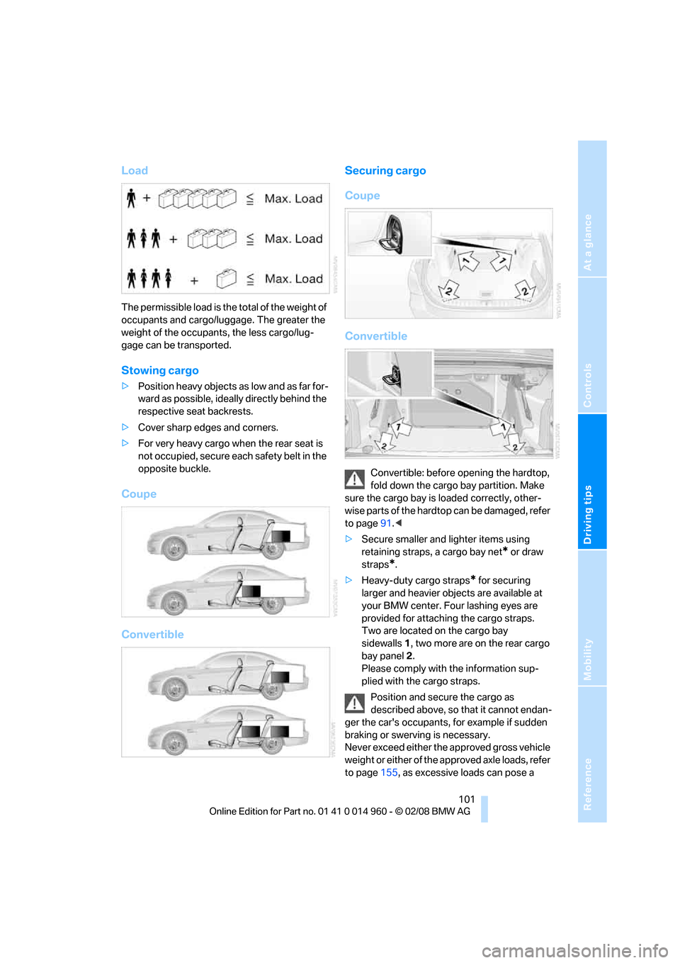
Stowing cargo
>Position heavy objects as low and as far for-
ward as possible, ideally directly behind the
respective seat backrests.
>Cover sharp edges and corners.
>For very heavy cargo when the rear seat is
not occupied, secure each safety belt in the
opposite buckle.
Coupe
ConvertibleSecuring cargo
Coupe
Convertible
Convertible: before opening the hardtop,
fold down the cargo bay partition. Make
sure the cargo bay is loaded correctly, other-
wise parts of the hardtop can be damaged, refer
to page91.<
>Secure smaller and lighter items using
retaining straps, a cargo bay net
* or draw
straps
*.
>Heavy-duty cargo straps
* for securing
larger and heavier objects are available at
your BMW center. Four lashing eyes are
provided for attaching the cargo straps.
Two are located on the cargo bay
sidewalls1, two more are on the rear cargo
bay panel2.
Please comply with the information sup-
plied with the cargo straps.
Position and secure the cargo as
described above, so that it cannot endan-
ger the car's occupants, for example if sudden
braking or swerving is necessary.
Never exceed either the approved gross vehicle
weight or either of the approved axle loads, refer
to page155, as excessive loads can pose a
Page 115 of 172
Reference
At a glance
Controls
Driving tips
Mobility
113
Temperature
The temperature grades are A, the highest, B,
and C, representing the tire's resistance to the
generation of heat and its ability to dissipate
heat when tested under controlled conditions
on a specified indoor laboratory test wheel.
Sustained high temperature can cause the
material of the tire to degenerate and reduce
tire life, and excessive temperature can lead to
sudden tire failure. The grade C corresponds to
a level of performance which all passenger car
tires must meet under the Federal Motor Vehi-
cle Safety Standard No. 109. Grades B and A
represent higher levels of performance on the
laboratory test wheel than the minimum
required by law.
The temperature grade for this tire is
established for a tire that is properly
inflated and not overloaded. Excessive speed,
underinflation, or excessive loading, either sep-
arately or in combination, can cause heat
buildup and possible tire failure.<
M+S
Winter and all-season tires.
These have better winter properties than sum-
mer tires.
XL
Designation for specially reinforced tires.
Tire condition
Inspect your tires frequently for tread wear,
signs of damage and for foreign objects lodged
in the tread. Check the tread depth.
Minimum tread depth
The tread depth should not drop below 1/8 in/
3 mm, although, for example, European legisla-
tion only specifies a minimum tread depth of
1/16 in/1.6 mm. At tread depths below 1/8 in/
3 mm there is an increased risk of high-speed
hydroplaning, even when only small amounts of
water are present on the road surface.
When winter tires wear down past a tread depth
of 1/6 in/4 mm, they become perceptibly less suitable for winter conditions. In the interest of
safety, new tires should be installed.
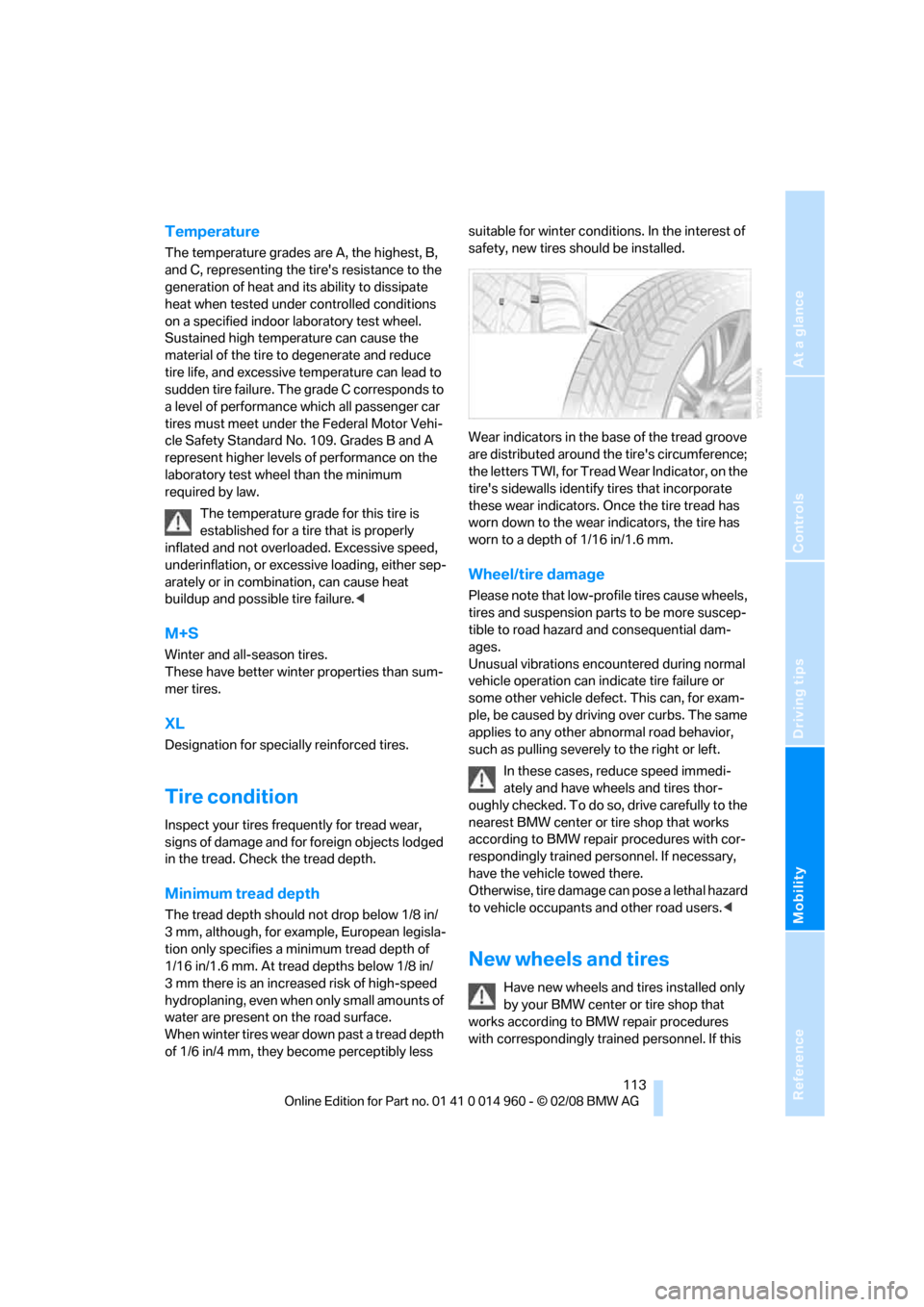
Wear indicators in the base of the tread groove
are distributed around the tire's circumference;
the letters TWI, for Tread Wear Indicator, on the
tire's sidewalls identify tires that incorporate
these wear indicators. Once the tire tread has
worn down to the wear indicators, the tire has
worn to a depth of 1/16 in/1.6 mm.
Wheel/tire damage
Please note that low-profile tires cause wheels,
tires and suspension parts to be more suscep-
tible to road hazard and consequential dam-
ages.
Unusual vibrations encountered during normal
vehicle operation can indicate tire failure or
some other vehicle defect. This can, for exam-
ple, be caused by driving over curbs. The same
applies to any other abnormal road behavior,
such as pulling severely to the right or left.
In these cases, reduce speed immedi-
ately and have wheels and tires thor-
oughly checked. To do so, drive carefully to the
nearest BMW center or tire shop that works
according to BMW repair procedures with cor-
respondingly trained personnel. If necessary,
have the vehicle towed there.
Otherwise, tire damage can pose a lethal hazard
to vehicle occupants and other road users.<
New wheels and tires
Have new wheels and tires installed only
by your BMW center or tire shop that
works according to BMW repair procedures
with correspondingly trained personnel. If this
Page 130 of 172
Replacing components
128 For care of the headlamps, please follow the
instructions in the chapter entitled 'Care'.
If the routine for changing a particular
bulb is not described here, please contact
your BMW center or a workshop that works
according to BMW repair procedures with cor-
respondingly trained personnel.<
Light-emitting diodes LED
Control elements, display components, part of
the exterior lighting and other interior equip-
ment in your vehicle are equipped with covered
light-emitting diodes as light sources. These
light-emitting diodes, which operate using a
concept similar to that applied in conventional
lasers, are officially designated as Class 1 light-
emitting diodes.
Do not remove the covers or expose the
eyes directly to the unfiltered light source
for several hours, otherwise this could cause
irritation to the retina.<
Xenon lamps
These bulbs have a very long service life and are
highly unlikely to fail.
Have any work on the xenon lamp system,
including bulb replacements, performed
o n ly b y a BM W c e n t e r o r a w o r k s h o p t h a t w o r k s
according to BMW repair procedures with cor-
respondingly trained personnel. Otherwise, if
such work is carried out improperly, the high
voltage in the system presents the danger of
fatal injuries.<
Access to the lamps
1.Switch off the lamps and take the remote
control out of the ignition lock.
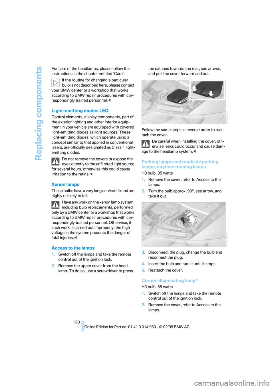
2.Remove the upper cover from the head-
lamp. To do so, use a screwdriver to press the catches towards the rear, see arrows,
and pull the cover forward and out.
Follow the same steps in reverse order to reat-
tach the cover.
Be careful when installing the cover, oth-
erwise leaks could occur and cause dam-
age to the headlamp system.<
Parking lamps and roadside parking
lamps, daytime running lamps
H8 bulb, 35 watts
1.Remove the cover, refer to Access to the
lamps.
2.Turn the bulb approx. 90°, see arrow, and
take it out.
3.Disconnect the plug, change the bulb and
reconnect the plug.
4.Insert the bulb and turn it until it stops.
5.Reattach the cover.
Corner-illuminating lamp*
H3 bulb, 55 watts
1.Switch off the lamps and take the remote
control out of the ignition lock.
2.Remove the cover, refer to Access to the
lamps.