BMW M3 SEDAN 2016 Owners Manual
Manufacturer: BMW, Model Year: 2016, Model line: M3 SEDAN, Model: BMW M3 SEDAN 2016Pages: 226, PDF Size: 4.86 MB
Page 191 of 226
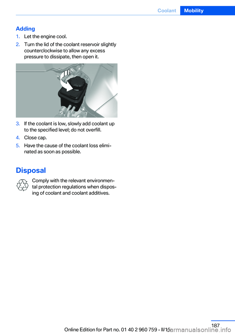
Adding1.Let the engine cool.2.Turn the lid of the coolant reservoir slightly
counterclockwise to allow any excess
pressure to dissipate, then open it.3.If the coolant is low, slowly add coolant up
to the specified level; do not overfill.4.Close cap.5.Have the cause of the coolant loss elimi‐
nated as soon as possible.
Disposal
Comply with the relevant environmen‐
tal protection regulations when dispos‐
ing of coolant and coolant additives.
Seite 187CoolantMobility187
Online Edition for Part no. 01 40 2 960 759 - II/15
Page 192 of 226
MaintenanceVehicle features and options
This chapter describes all standard, country-
specific and optional features offered with the
series. It also describes features that are not
necessarily available in your car, e. g., due to
the selected options or country versions. This
also applies to safety-related functions and
systems. The respectively applicable country
provisions must be observed when using the
respective features and systems.
BMW maintenance system The maintenance system indicates required
maintenance measures, and thereby provides
support in maintaining road safety and the op‐
erational reliability of the vehicle.
In some cases scopes and intervals may vary
according to the country-specific version. Re‐
placement work, spare parts, fuels and lubri‐
cants and wear materials are calculated sepa‐
rately. Additional information is available from
the service center.
Condition Based Service
CBS
Sensors and special algorithms take into ac‐
count the driving conditions of your vehicle.
Based on this, Condition Based Service recog‐
nizes the maintenance requirements.
The system makes it possible to adapt the
amount of maintenance corresponding to your
user profile.
Detailed information on service requirements,
refer to page 83, can be displayed on the Con‐
trol Display.Service data in the remote control
Information on the required maintenance is
continuously stored in the remote control. Your service center will read out this data and
suggest the right array of service procedures for your vehicle.
Therefore, hand your service specialist the re‐
mote control with which the vehicle was driven
most recently.
Storage periods Storage periods during which the vehicle bat‐
tery was disconnected are not taken into ac‐
count.
If this occurs, have a service center update the
time-dependent maintenance procedures,
such as checking brake fluid and, if needed,
changing the engine oil and the microfilter/
activated-charcoal filter.
Service and Warranty
Information Booklet for US
models and Warranty and
Service Guide Booklet for
Canadian models
Please consult your Service and Warranty In‐
formation Booklet for US models and Warranty
and Service Guide Booklet for Canadian mod‐
els for additional information on service re‐
quirements.
Maintenance and repair should be performed
by your service center. Make sure to have reg‐
ular maintenance procedures recorded in the
vehicle's Service and Warranty Information
Booklet for US models, and in the Warranty
and Service Guide Booklet for Canadian mod‐
els. These entries are proof of regular mainte‐
nance.Seite 188MobilityMaintenance188
Online Edition for Part no. 01 40 2 960 759 - II/15
Page 193 of 226
Socket for OBD Onboard
Diagnosis
Note Socket for Onboard Diagnosis
The socket for onboard diagnostics may
only be used by the service center or a work‐
shop that operates in accordance with the
specifications of the vehicle manufacturer with
correspondingly trained personnel and other
authorized persons. Otherwise, use may result
in operating problems for the vehicle.◀
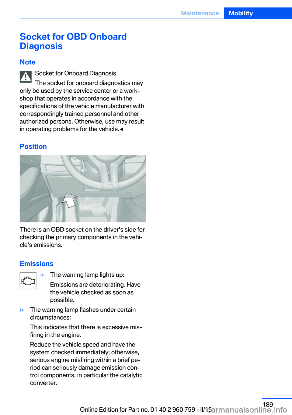
Position
There is an OBD socket on the driver's side for
checking the primary components in the vehi‐
cle's emissions.
Emissions
▷The warning lamp lights up:
Emissions are deteriorating. Have
the vehicle checked as soon as
possible.▷The warning lamp flashes under certain
circumstances:
This indicates that there is excessive mis‐
firing in the engine.
Reduce the vehicle speed and have the
system checked immediately; otherwise,
serious engine misfiring within a brief pe‐
riod can seriously damage emission con‐
trol components, in particular the catalytic
converter.Seite 189MaintenanceMobility189
Online Edition for Part no. 01 40 2 960 759 - II/15
Page 194 of 226
Replacing componentsVehicle features and optionsThis chapter describes all standard, country-
specific and optional features offered with the
series. It also describes features that are not
necessarily available in your car, e. g., due to
the selected options or country versions. This
also applies to safety-related functions and
systems. The respectively applicable country
provisions must be observed when using the
respective features and systems.
Onboard vehicle tool kit
The onboard vehicle tool kit is located on the
right side in the trunk in a storage compart‐
ment. Open the cover.
Wiper blade replacement
Note Do not fold down the wipers without
wiper blades
Do not fold down the wipers if wiper blades
have not been installed; this may damage the
windshield.◀
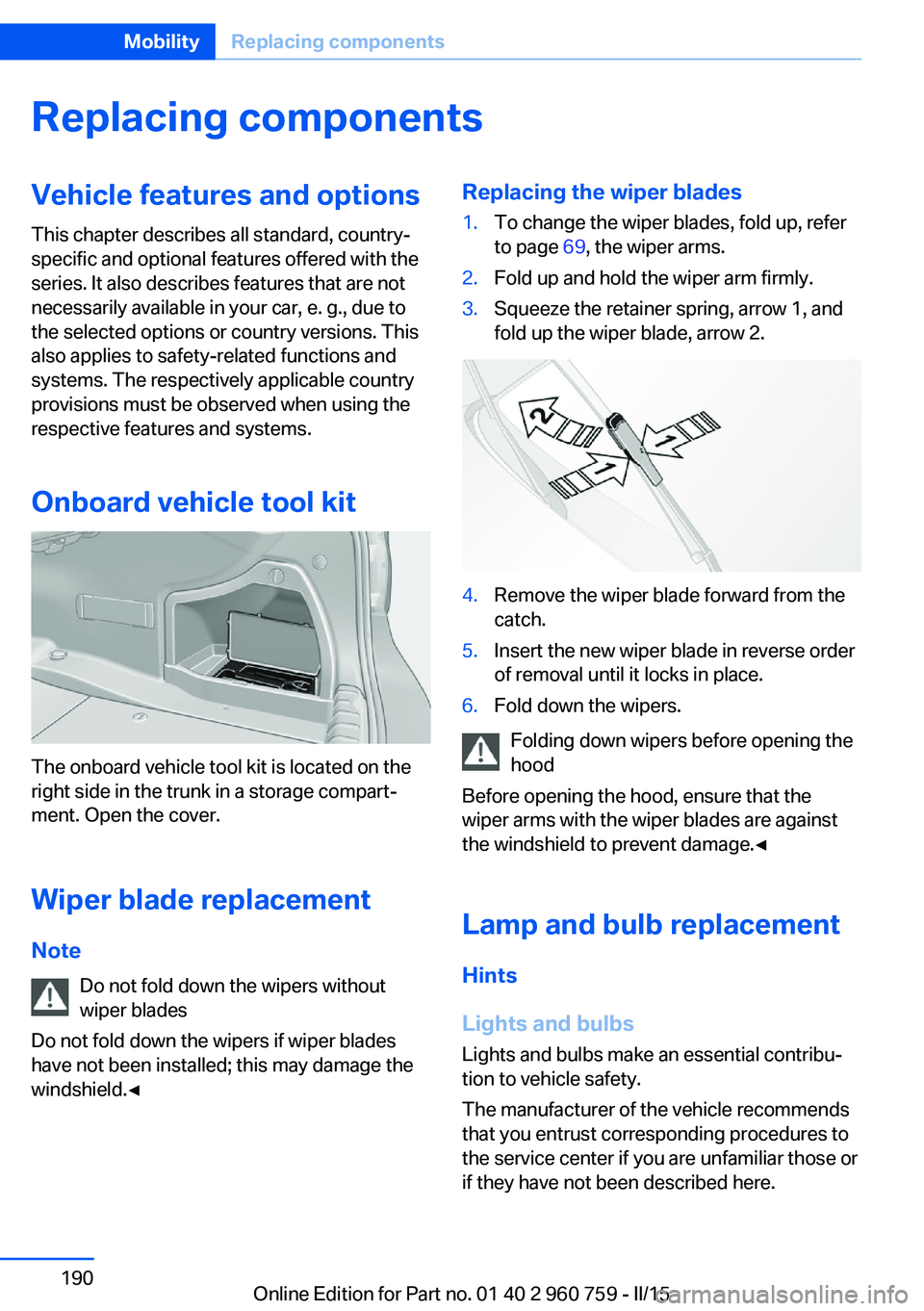
Replacing the wiper blades1.To change the wiper blades, fold up, refer
to page 69, the wiper arms.2.Fold up and hold the wiper arm firmly.3.Squeeze the retainer spring, arrow 1, and
fold up the wiper blade, arrow 2.4.Remove the wiper blade forward from the
catch.5.Insert the new wiper blade in reverse order
of removal until it locks in place.6.Fold down the wipers.
Folding down wipers before opening the hood
Before opening the hood, ensure that the
wiper arms with the wiper blades are against
the windshield to prevent damage.◀
Lamp and bulb replacement
Hints
Lights and bulbs Lights and bulbs make an essential contribu‐
tion to vehicle safety.
The manufacturer of the vehicle recommends
that you entrust corresponding procedures to
the service center if you are unfamiliar those or
if they have not been described here.
Seite 190MobilityReplacing components190
Online Edition for Part no. 01 40 2 960 759 - II/15
Page 195 of 226
You can obtain a selection of replacement
bulbs at the service center.
Danger of burns
Only change bulbs when they are cool;
otherwise, there is a danger of getting
burned.◀
Working on the lighting system
When working on the lighting system,
you should always reel off the lights affected to
prevent short circuits.
To avoid possible injury or equipment damage
when replacing bulbs, observe any instructions
provided by the bulb manufacturer.◀
Do not perform work/bulb replacement
on xenon headlights
Have any work on the xenon lighting system,
including bulb replacement, performed only by
a service center. Due to the high voltage
present in the system, there is a danger of fatal
injuries if work is carried out improperly.◀
Do not touch the bulbs
Do not touch the glass of new bulbs with
your bare hands, as even minute amounts of
contamination will burn into the bulb's surface
and reduce its service life.
Use a clean tissue, cloth or something similar,
or hold the bulb by its base.◀
Light-emitting diodes (LEDs)
Some items of equipment use light-emitting
diodes installed behind a cover as a light
source.
These light-emitting diodes, which are related
to conventional lasers, are officially designated as Class 1 light-emitting diodes.
Do not remove the covers
Do not remove the covers, and never
stare into the unfiltered light for several hours;
otherwise, irritation of the retina could result.◀Headlight glass
Condensation can form on the inside of the ex‐
ternal lights in cool or humid weather. When
driving with the light switched on, the conden‐
sation evaporates after a short time. The head‐
light glass does not need to be changed.
If the headlights do not dim despite driving
with the light switched on, increasing humidity
forms, e. g. water droplets in the light, have the service center check this.
Headlight setting The headlight adjustments can be affected by
changing lights and bulbs. Have the head‐
lights' settings checked and corrected by serv‐
ice after a replacement.
Front lights, bulb replacement
Xenon headlights
Xenon headlights
Because of the long life of these bulbs, the
likelihood of failure is very low. Switching the
lights on and off frequently shortens their life.
Do not perform work/bulb replacement
on xenon headlights
Have any work on the xenon lighting system,
including bulb replacement, performed only by
a service center. Due to the high voltage present in the system, there is a danger of fatal
injuries if work is carried out improperly.◀
For checking and adjusting headlamp aim,
please contact your BMW center.Seite 191Replacing componentsMobility191
Online Edition for Part no. 01 40 2 960 759 - II/15
Page 196 of 226
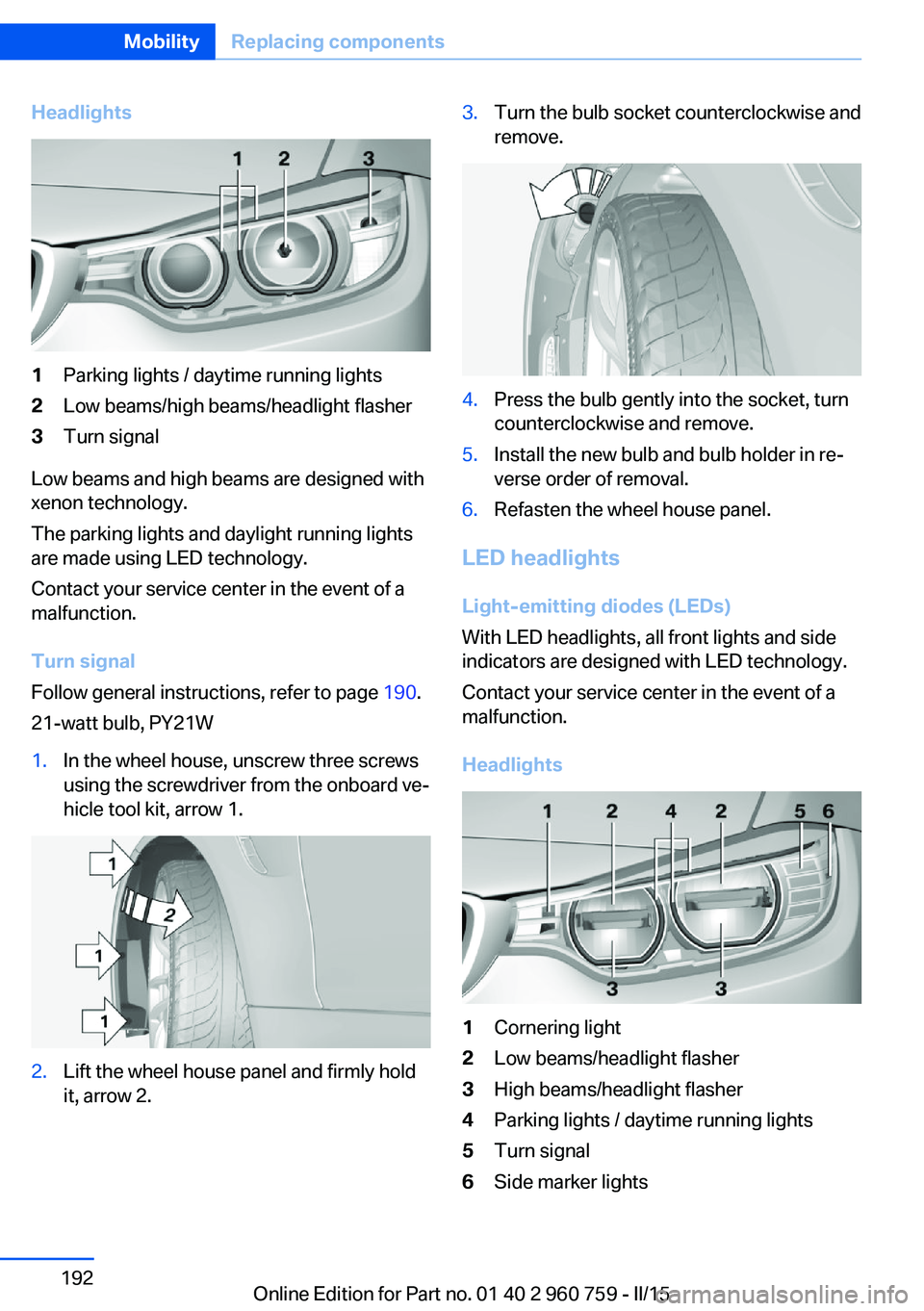
Headlights1Parking lights / daytime running lights2Low beams/high beams/headlight flasher3Turn signal
Low beams and high beams are designed with
xenon technology.
The parking lights and daylight running lights
are made using LED technology.
Contact your service center in the event of a
malfunction.
Turn signal
Follow general instructions, refer to page 190.
21-watt bulb, PY21W
1.In the wheel house, unscrew three screws
using the screwdriver from the onboard ve‐
hicle tool kit, arrow 1.2.Lift the wheel house panel and firmly hold
it, arrow 2.3.Turn the bulb socket counterclockwise and
remove.4.Press the bulb gently into the socket, turn
counterclockwise and remove.5.Install the new bulb and bulb holder in re‐
verse order of removal.6.Refasten the wheel house panel.
LED headlights
Light-emitting diodes (LEDs)
With LED headlights, all front lights and side
indicators are designed with LED technology.
Contact your service center in the event of a
malfunction.
Headlights
1Cornering light2Low beams/headlight flasher3High beams/headlight flasher4Parking lights / daytime running lights5Turn signal6Side marker lightsSeite 192MobilityReplacing components192
Online Edition for Part no. 01 40 2 960 759 - II/15
Page 197 of 226
Contact your service center in the event of a
malfunction.
Turn signal in exterior mirrorFollow general instructions, refer to page 190.
The turn signals in the exterior mirrors feature
LED technology. Contact your service center in the event of a malfunction.
Tail lights, bulb replacement
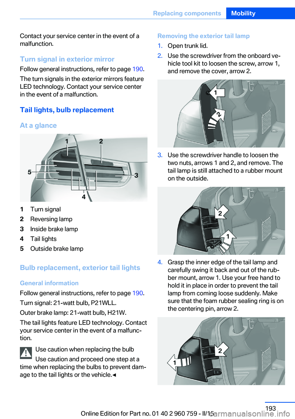
At a glance1Turn signal2Reversing lamp3Inside brake lamp4Tail lights5Outside brake lamp
Bulb replacement, exterior tail lights General information
Follow general instructions, refer to page 190.
Turn signal: 21-watt bulb, P21WLL.
Outer brake lamp: 21-watt bulb, H21W.
The tail lights feature LED technology. Contact
your service center in the event of a malfunc‐
tion.
Use caution when replacing the bulb
Use caution and proceed one step at a
time when replacing the bulbs to prevent dam‐
age to the tail lights or the vehicle.◀
Removing the exterior tail lamp1.Open trunk lid.2.Use the screwdriver from the onboard ve‐
hicle tool kit to loosen the screw, arrow 1,
and remove the cover, arrow 2.3.Use the screwdriver handle to loosen the
two nuts, arrows 1 and 2, and remove. The
tail lamp is still attached to a rubber mount
on the outside.4.Grasp the inner edge of the tail lamp and
carefully swing it back and out of the rub‐
ber mount, arrow 1. Use your free hand to
hold it in place in order to prevent the tail
lamp from coming loose suddenly. Make
sure that the foam rubber sealing ring is on
the centering pin, arrow 2.Seite 193Replacing componentsMobility193
Online Edition for Part no. 01 40 2 960 759 - II/15
Page 198 of 226
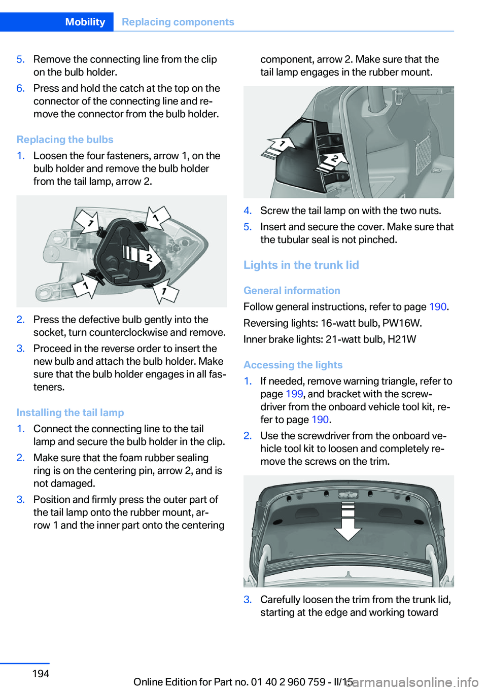
5.Remove the connecting line from the clip
on the bulb holder.6.Press and hold the catch at the top on the
connector of the connecting line and re‐
move the connector from the bulb holder.
Replacing the bulbs
1.Loosen the four fasteners, arrow 1, on the
bulb holder and remove the bulb holder
from the tail lamp, arrow 2.2.Press the defective bulb gently into the
socket, turn counterclockwise and remove.3.Proceed in the reverse order to insert the
new bulb and attach the bulb holder. Make
sure that the bulb holder engages in all fas‐
teners.
Installing the tail lamp
1.Connect the connecting line to the tail
lamp and secure the bulb holder in the clip.2.Make sure that the foam rubber sealing
ring is on the centering pin, arrow 2, and is
not damaged.3.Position and firmly press the outer part of
the tail lamp onto the rubber mount, ar‐
row 1 and the inner part onto the centeringcomponent, arrow 2. Make sure that the
tail lamp engages in the rubber mount.4.Screw the tail lamp on with the two nuts.5.Insert and secure the cover. Make sure that
the tubular seal is not pinched.
Lights in the trunk lid
General information
Follow general instructions, refer to page 190.
Reversing lights: 16-watt bulb, PW16W.
Inner brake lights: 21-watt bulb, H21W
Accessing the lights
1.If needed, remove warning triangle, refer to
page 199, and bracket with the screw‐
driver from the onboard vehicle tool kit, re‐
fer to page 190.2.Use the screwdriver from the onboard ve‐
hicle tool kit to loosen and completely re‐
move the screws on the trim.3.Carefully loosen the trim from the trunk lid,
starting at the edge and working towardSeite 194MobilityReplacing components194
Online Edition for Part no. 01 40 2 960 759 - II/15
Page 199 of 226
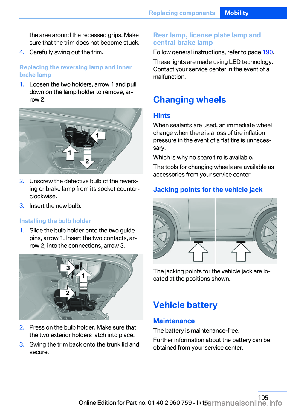
the area around the recessed grips. Make
sure that the trim does not become stuck.4.Carefully swing out the trim.
Replacing the reversing lamp and inner
brake lamp
1.Loosen the two holders, arrow 1 and pull
down on the lamp holder to remove, ar‐
row 2.2.Unscrew the defective bulb of the revers‐
ing or brake lamp from its socket counter‐
clockwise.3.Insert the new bulb.
Installing the bulb holder
1.Slide the bulb holder onto the two guide
pins, arrow 1. Insert the two contacts, ar‐
row 2, into the connections, arrow 3.2.Press on the bulb holder. Make sure that
the two exterior holders latch into place.3.Swing the trim back onto the trunk lid and
secure.Rear lamp, license plate lamp and
central brake lamp
Follow general instructions, refer to page 190.
These lights are made using LED technology.
Contact your service center in the event of a
malfunction.
Changing wheels
Hints When sealants are used, an immediate wheel
change when there is a loss of tire inflation
pressure in the event of a flat tire is unneces‐
sary.
Which is why no spare tire is available.
The tools for changing wheels are available as
accessories from your service center.
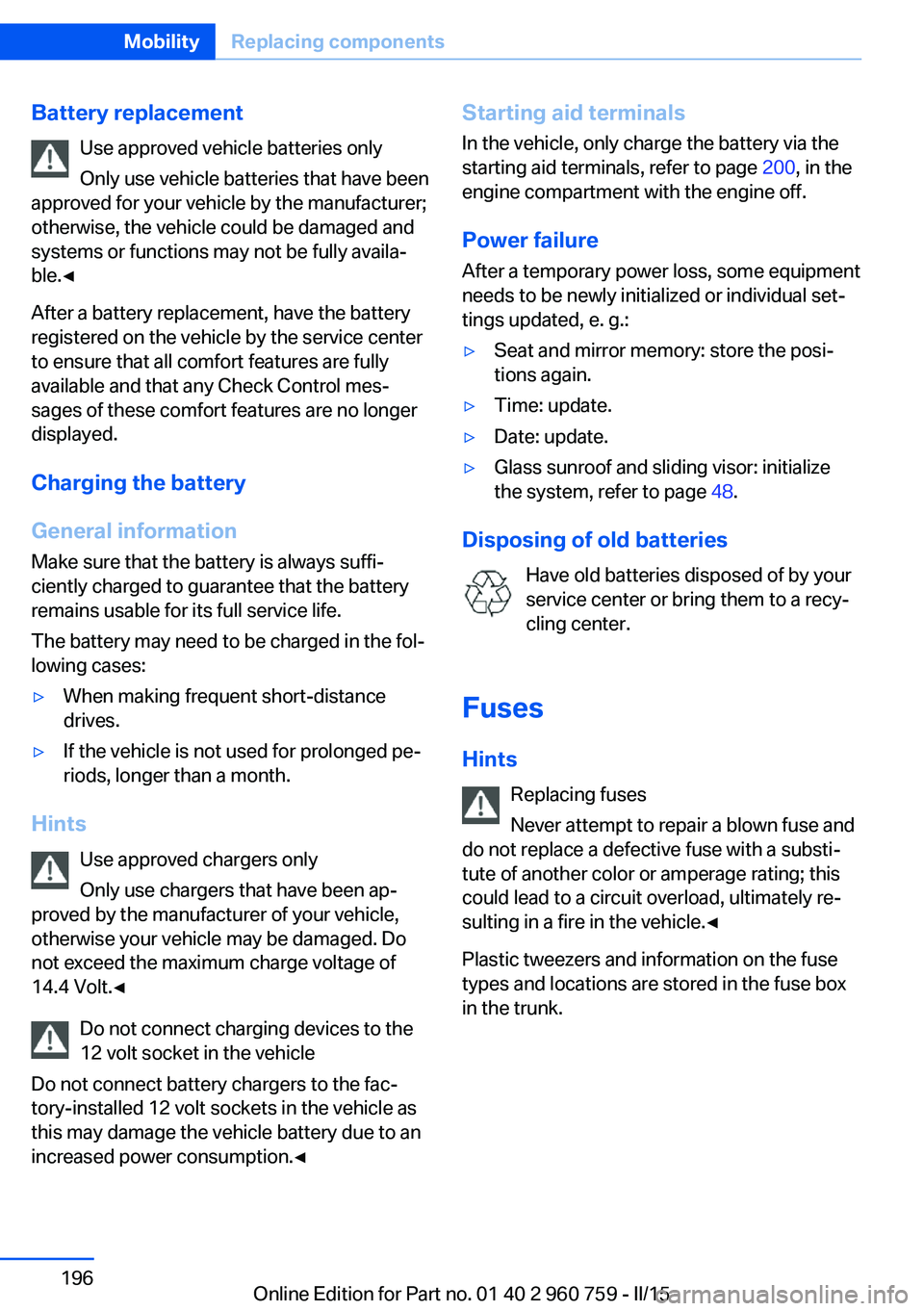
Jacking points for the vehicle jack
The jacking points for the vehicle jack are lo‐
cated at the positions shown.
Vehicle battery Maintenance
The battery is maintenance-free.
Further information about the battery can be
obtained from your service center.
Seite 195Replacing componentsMobility195
Online Edition for Part no. 01 40 2 960 759 - II/15
Page 200 of 226
Battery replacementUse approved vehicle batteries only
Only use vehicle batteries that have been
approved for your vehicle by the manufacturer;
otherwise, the vehicle could be damaged and
systems or functions may not be fully availa‐
ble.◀
After a battery replacement, have the battery registered on the vehicle by the service center
to ensure that all comfort features are fully
available and that any Check Control mes‐
sages of these comfort features are no longer
displayed.
Charging the battery
General information Make sure that the battery is always suffi‐
ciently charged to guarantee that the battery
remains usable for its full service life.
The battery may need to be charged in the fol‐
lowing cases:▷When making frequent short-distance
drives.▷If the vehicle is not used for prolonged pe‐
riods, longer than a month.
Hints
Use approved chargers only
Only use chargers that have been ap‐
proved by the manufacturer of your vehicle, otherwise your vehicle may be damaged. Do
not exceed the maximum charge voltage of
14.4 Volt.◀
Do not connect charging devices to the
12 volt socket in the vehicle
Do not connect battery chargers to the fac‐
tory-installed 12 volt sockets in the vehicle as
this may damage the vehicle battery due to an
increased power consumption.◀
Starting aid terminals
In the vehicle, only charge the battery via the
starting aid terminals, refer to page 200, in the
engine compartment with the engine off.
Power failure After a temporary power loss, some equipment
needs to be newly initialized or individual set‐
tings updated, e. g.:▷Seat and mirror memory: store the posi‐
tions again.▷Time: update.▷Date: update.▷Glass sunroof and sliding visor: initialize
the system, refer to page 48.
Disposing of old batteries
Have old batteries disposed of by your
service center or bring them to a recy‐
cling center.
Fuses Hints Replacing fuses
Never attempt to repair a blown fuse and
do not replace a defective fuse with a substi‐
tute of another color or amperage rating; this could lead to a circuit overload, ultimately re‐
sulting in a fire in the vehicle.◀
Plastic tweezers and information on the fuse
types and locations are stored in the fuse box
in the trunk.
Seite 196MobilityReplacing components196
Online Edition for Part no. 01 40 2 960 759 - II/15