air condition BMW M4 2016 Owners Manual
[x] Cancel search | Manufacturer: BMW, Model Year: 2016, Model line: M4, Model: BMW M4 2016Pages: 228, PDF Size: 4.88 MB
Page 8 of 228
Further information is available from a Service
Partner or a qualified specialist workshop.
Maintenance and repair
Advanced technology behind this vehicle, for
example the use of modern materials and high-
performance electronics, necessitates adapted
methods of maintenance and repair.
The manufacturer of the vehicle recommends
having respective work carried out by a BMW
Service Partner or a qualified specialist work‐
shop. Qualified specialist workshop in this
Owner's Handbook refers to a workshop carry‐
ing out respective work, e.g. maintenance and
repair, according to BMW specifications with
respectively trained personnel.
If such work, e.g maintenance and repair, is
performed inexpertly, it could result in conse‐
quential damage and thus constitute a safety
risk.
Parts and accessories BMW recommends using parts and accessory
products that are approved by BMW and thus
categorised as suitable.
The manufacturer of your vehicle recommends
to consult with a BMW Service Partner prior to
purchasing spare parts, operating materials or
accessories. The BMW Service Partner in‐
forms about genuine BMW parts and accesso‐
ries, other BMW approved products and offers
expert advice on all related matters.
The safety and compatibility of genuine BMW
parts and accessories in conjunction with
BMW vehicles have been checked by BMW.
BMW accepts product liability for them. On the
other hand, BMW cannot accept liability for un‐
suitable parts or accessory products of any
kind.
BMW does not evaluate each individual prod‐
uct of outside origin as to its suitability for use
on BMW vehicles without safety risk. BMW
does not evaluate the suitability of products,
even if a country-specific official approval wasissued. BMW cannot evaluate, whether these
products are suitable for BMW vehicles under
all usage conditions.
Data memory Many of the electronic components of your ve‐
hicle contain data memories, which save tech‐
nical information on vehicle condition, events
and errors temporarily or permanently. This
technical information documents the condition
of a component, a module, a system or its en‐
vironment:▷Operating states of system components,
for example, fill levels.▷Status messages of the vehicle and indi‐
vidual components, for example, wheel ro‐
tation number/speed, movement delay,
transverse acceleration.▷Malfunctions and faults of important sys‐
tem components, for example, lights and
brakes.▷Responses of the vehicle to special driving
situations, for example, triggering of an air‐
bag, using the stability control systems.▷Ambient conditions, for example, tempera‐
ture.
This data is only of a technical nature and is for
detecting and rectifying faults and optimisation
of vehicle functions. Movement profiles over
driven routes cannot be created from this data.
When servicing, for example, during repairs,
service processes, warranty cases or quality
assurance, this technical information can be
read by employees of the Service Partner or a
qualified specialist workshop, including the
manufacturer, from the event and fault data
memories with special diagnostic tools. There,
you will receive further information as needed.
After rectifying the fault, the information in the
fault memory is deleted or continuously over‐
written.
When using the vehicle, situations are conceiv‐
able in which this technical data can be per‐
Seite 8Notes8
Online Edition for Part no. 01 40 2 964 013 - VI/15
Page 16 of 228
iDriveVehicle equipment
This chapter describes all standard, national
and special equipment provided in the model
series. Equipment not available in the vehicle is
therefore also described, for example the se‐
lected special equipment or national version.
This also applies to safety-relevant functions
and systems. Comply with the relevant na‐
tional regulations when using the correspond‐
ing functions and systems.
Principle
iDrive integrates the functions of a large num‐
ber of switches. These functions can therefore
be controlled from one central point.
WARNING
Operating integrated information sys‐
tems and communication devices during the
journey can distract from traffic. You could lose control of the vehicle. Danger of accidents.
Only operate the systems or devices if permis‐
sible in the traffic situation. Stop if necessary
and operate the systems or devices with the
vehicle at a standstill.◀Overview of controls
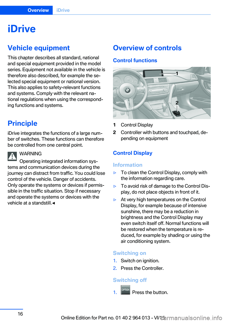
Control functions1Control Display2Controller with buttons and touchpad, de‐
pending on equipment
Control Display
Information
▷To clean the Control Display, comply with
the information regarding care.▷To avoid risk of damage to the Control Dis‐
play, do not place objects in front of it.▷At very high temperatures on the Control
Display, for example because of intensive
sunshine, there may be a reduction in
brightness and the Control Display may
even switch itself off. Normal functions will
be restored when the temperature is re‐
duced, for example by shading or using the
air conditioning system.
Switching on
1.Switch on ignition.2.Press the Controller.
Switching off
1. Press the button.
Seite 16OverviewiDrive16
Online Edition for Part no. 01 40 2 964 013 - VI/15
Page 34 of 228
If several drivers each use their own remote
control, the vehicle will adapt to their personal
settings when it is unlocked. These settings
are also resaved if the vehicle is used in the in‐
tervening period by someone with a different
remote control.
Changes to settings are saved automatically in
the personal profile.
Three personal profiles and a guest profile can
be created.
Settings
Settings for the following systems and func‐
tions are saved in the active profile. The extent
of settings that can be saved depends on the
country and equipment.▷Unlocking and locking.▷Light.▷Air conditioning.▷Radio.▷Instrument cluster.▷Favourites buttons.▷Volumes, sound.▷Control Display.▷Navigation.▷TV.▷Park Distance Control PDC.▷Rear-view camera.▷Side view.▷Head-Up Display.▷M Drive: configurations.▷Driver's seat position, exterior mirror posi‐
tion, steering wheel position.▷Cruise Control.▷Intelligent Safety.▷Lane change warning.Profile management
Calling up profiles Independently of the remote control that is
used, another profile can be called up.
Via iDrive:1."Settings"2."Profiles"3.Select a profile.▷The settings saved in the called-up profile
are made automatically.▷The profile called up is assigned to the re‐
mote control currently used.▷If the profile has already been allocated to
another remote control, this profile applies
to both remote controls. It is no longer
possible to differentiate between the set‐
tings of both remote controls.
Renaming profiles
To avoid mixing up the profiles, each profile
can be given a personal name.
On the Control Display:
1."Settings"2."Profiles"3.Call up "Options".4."Rename current profile"
Resetting profiles Settings of the active profile are reset to fac‐
tory settings.
On the Control Display:
1."Settings"2."Profiles"3.Call up "Options".4."Reset current profile"
Exporting profiles Most of the settings of the active profile can be
exported.
Seite 34ControlsOpening and closing34
Online Edition for Part no. 01 40 2 964 013 - VI/15
Page 48 of 228
AdjustingVehicle equipment
This chapter describes all standard, national
and special equipment provided in the model
series. Equipment not available in the vehicle is
therefore also described, for example the se‐
lected special equipment or national version.
This also applies to safety-relevant functions
and systems. Comply with the relevant na‐
tional regulations when using the correspond‐
ing functions and systems.
Safe seated position A seated position that suitably reflects your re‐
quirements is a vital condition of relaxed driv‐
ing with a minimum of fatigue.
In the event of an accident, the seated position
plays an important role together with:▷Seat belts, see page 52.▷Head restraints, see page 54.▷Airbags, see page 104.
Seats
Notes WARNING
Seat adjustment during the journey can
lead to unexpected seat movements. You
could lose control of the vehicle. Danger of ac‐
cidents. Only adjust the seat on the driver side
when at a standstill.◀
WARNING
If the seat backrest is angled back too
far, the protective effect of the seat belt will no
longer be guaranteed. There is a danger of
slipping under the seat belt in the event of an
accident. Danger of injury or life. Set the seat
before starting the journey. Place the seat
backrest in the most upright possible position,
and do not change it during the journey.◀
WARNING
Danger of trapping when moving the
seats. Danger of injury or damage to property.
Before making the setting, make sure that the
movement area of the seat is clear.◀
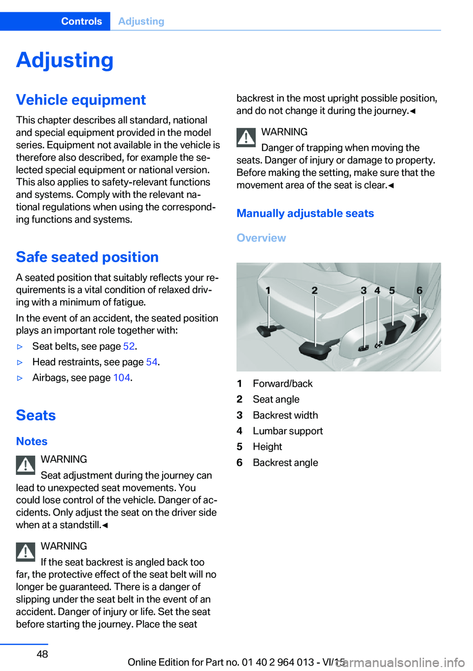
Manually adjustable seats
Overview1Forward/back2Seat angle3Backrest width4Lumbar support5Height6Backrest angleSeite 48ControlsAdjusting48
Online Edition for Part no. 01 40 2 964 013 - VI/15
Page 68 of 228
▷Driver's seat belt buckled or driver's door
closed.
The air flow rate of the air conditioning system
is reduced when the engine is not running.
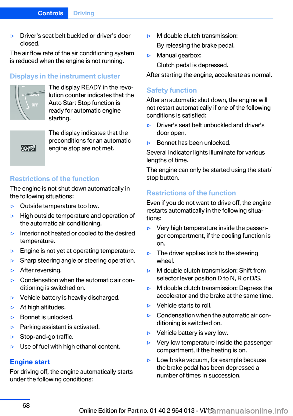
Displays in the instrument cluster The display READY in the revo‐
lution counter indicates that the
Auto Start Stop function is
ready for automatic engine
starting.
The display indicates that the preconditions for an automatic
engine stop are not met.
Restrictions of the function The engine is not shut down automatically in
the following situations:
▷Outside temperature too low.▷High outside temperature and operation of
the automatic air conditioning.▷Interior not heated or cooled to the desired
temperature.▷Engine is not yet at operating temperature.▷Sharp steering angle or steering operation.▷After reversing.▷Condensation when the automatic air con‐
ditioning is switched on.▷Vehicle battery is heavily discharged.▷At high altitudes.▷Bonnet is unlocked.▷Parking assistant is activated.▷Stop-and-go traffic.▷Use of fuel with high ethanol content.
Engine start
For driving off, the engine automatically starts
under the following conditions:
▷M double clutch transmission:
By releasing the brake pedal.▷Manual gearbox:
Clutch pedal is depressed.
After starting the engine, accelerate as normal.
Safety function After an automatic shut down, the engine will
not restart automatically if one of the following
conditions is satisfied:
▷Driver's seat belt unbuckled and driver's
door open.▷Bonnet has been unlocked.
Several indicator lights illuminate for various
lengths of time.
The engine can only be started using the start/
stop button.
Restrictions of the function
Even if you do not want to drive off, the engine
restarts automatically in the following situa‐
tions:
▷Very high temperature inside the passen‐
ger compartment, if the cooling function is
on.▷The driver applies lock to the steering
wheel.▷M double clutch transmission: Shift from
selector lever position D to N, R or D/S.▷M double clutch transmission: Depress the
accelerator and the brake at the same time.▷Vehicle starts to roll.▷Condensation when the automatic air con‐
ditioning is switched on.▷Vehicle battery is very low.▷Very low temperature inside the passenger
compartment, if the heating is on.▷Low brake vacuum, for example because
the brake pedal has been depressed a
number of times in succession.Seite 68ControlsDriving68
Online Edition for Part no. 01 40 2 964 013 - VI/15
Page 86 of 228
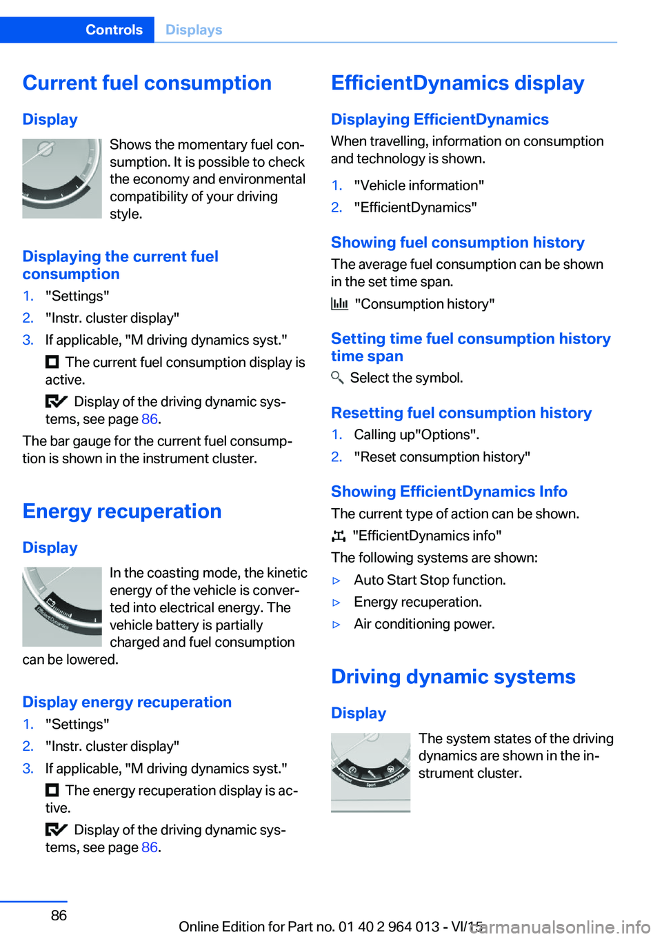
Current fuel consumption
Display Shows the momentary fuel con‐
sumption. It is possible to check
the economy and environmental
compatibility of your driving
style.
Displaying the current fuel
consumption1."Settings"2."Instr. cluster display"3.If applicable, "M driving dynamics syst."
The current fuel consumption display is
active.
Display of the driving dynamic sys‐
tems, see page 86.
The bar gauge for the current fuel consump‐
tion is shown in the instrument cluster.
Energy recuperation
Display In the coasting mode, the kinetic
energy of the vehicle is conver‐
ted into electrical energy. The
vehicle battery is partially
charged and fuel consumption
can be lowered.
Display energy recuperation
1."Settings"2."Instr. cluster display"3.If applicable, "M driving dynamics syst."
The energy recuperation display is ac‐
tive.
Display of the driving dynamic sys‐
tems, see page 86.
EfficientDynamics display
Displaying EfficientDynamics When travelling, information on consumption
and technology is shown.1."Vehicle information"2."EfficientDynamics"
Showing fuel consumption history
The average fuel consumption can be shown
in the set time span.
"Consumption history"
Setting time fuel consumption history
time span
Select the symbol.
Resetting fuel consumption history
1.Calling up"Options".2."Reset consumption history"
Showing EfficientDynamics Info
The current type of action can be shown.
"EfficientDynamics info"
The following systems are shown:
▷Auto Start Stop function.▷Energy recuperation.▷Air conditioning power.
Driving dynamic systems
Display The system states of the driving
dynamics are shown in the in‐
strument cluster.
Seite 86ControlsDisplays86
Online Edition for Part no. 01 40 2 964 013 - VI/15
Page 101 of 228
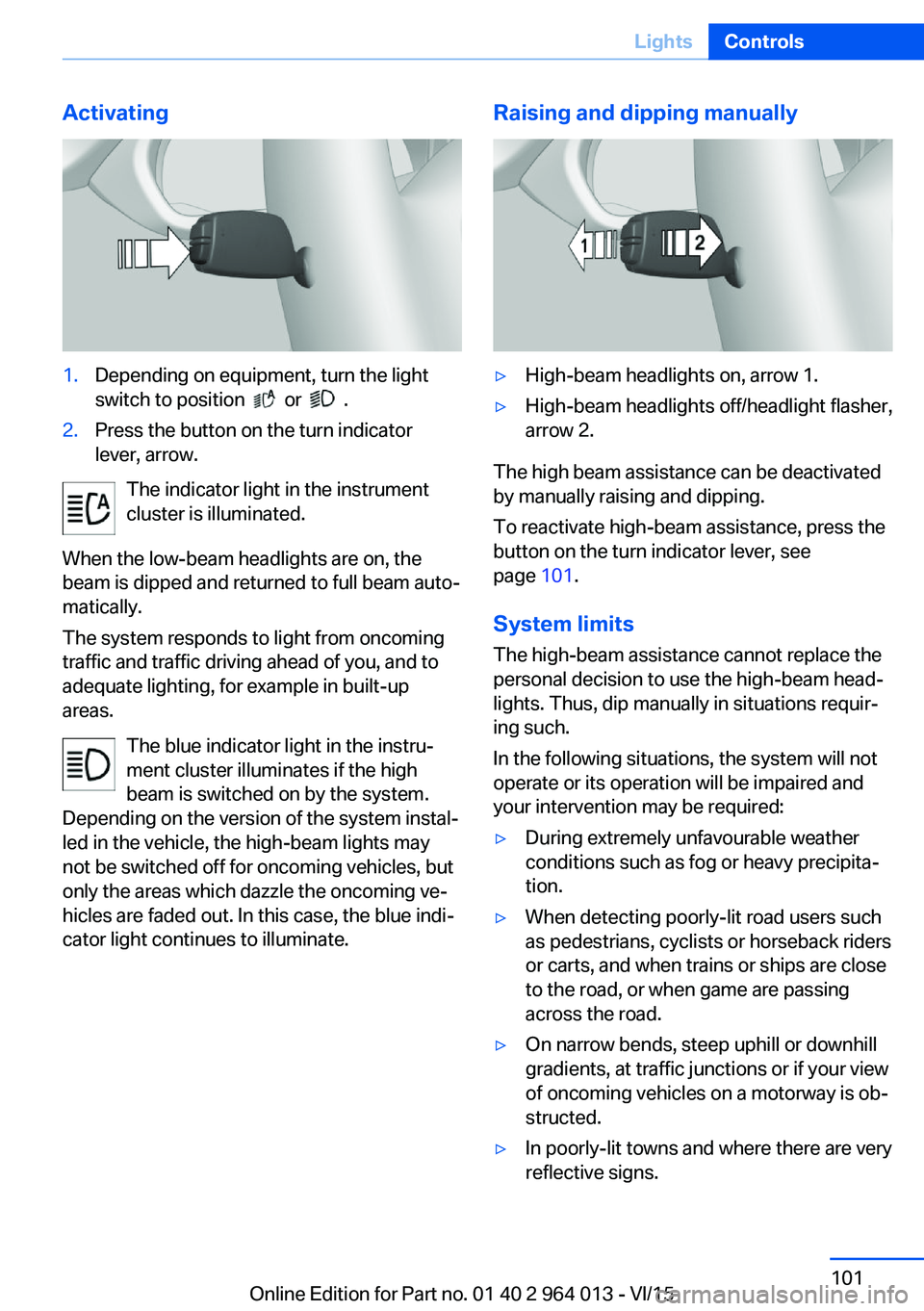
Activating1.Depending on equipment, turn the light
switch to position
or .
2.Press the button on the turn indicator
lever, arrow.
The indicator light in the instrument
cluster is illuminated.
When the low-beam headlights are on, the
beam is dipped and returned to full beam auto‐
matically.
The system responds to light from oncoming
traffic and traffic driving ahead of you, and to
adequate lighting, for example in built-up
areas.
The blue indicator light in the instru‐
ment cluster illuminates if the high
beam is switched on by the system.
Depending on the version of the system instal‐
led in the vehicle, the high-beam lights may
not be switched off for oncoming vehicles, but
only the areas which dazzle the oncoming ve‐
hicles are faded out. In this case, the blue indi‐
cator light continues to illuminate.
Raising and dipping manually▷High-beam headlights on, arrow 1.▷High-beam headlights off/headlight flasher,
arrow 2.
The high beam assistance can be deactivated
by manually raising and dipping.
To reactivate high-beam assistance, press the
button on the turn indicator lever, see
page 101.
System limits
The high-beam assistance cannot replace the
personal decision to use the high-beam head‐
lights. Thus, dip manually in situations requir‐
ing such.
In the following situations, the system will not
operate or its operation will be impaired and
your intervention may be required:
▷During extremely unfavourable weather
conditions such as fog or heavy precipita‐
tion.▷When detecting poorly-lit road users such
as pedestrians, cyclists or horseback riders
or carts, and when trains or ships are close
to the road, or when game are passing
across the road.▷On narrow bends, steep uphill or downhill
gradients, at traffic junctions or if your view
of oncoming vehicles on a motorway is ob‐
structed.▷In poorly-lit towns and where there are very
reflective signs.Seite 101LightsControls101
Online Edition for Part no. 01 40 2 964 013 - VI/15
Page 106 of 228
Not for Australia/New Zealand: Key
switch for front passenger airbags
General
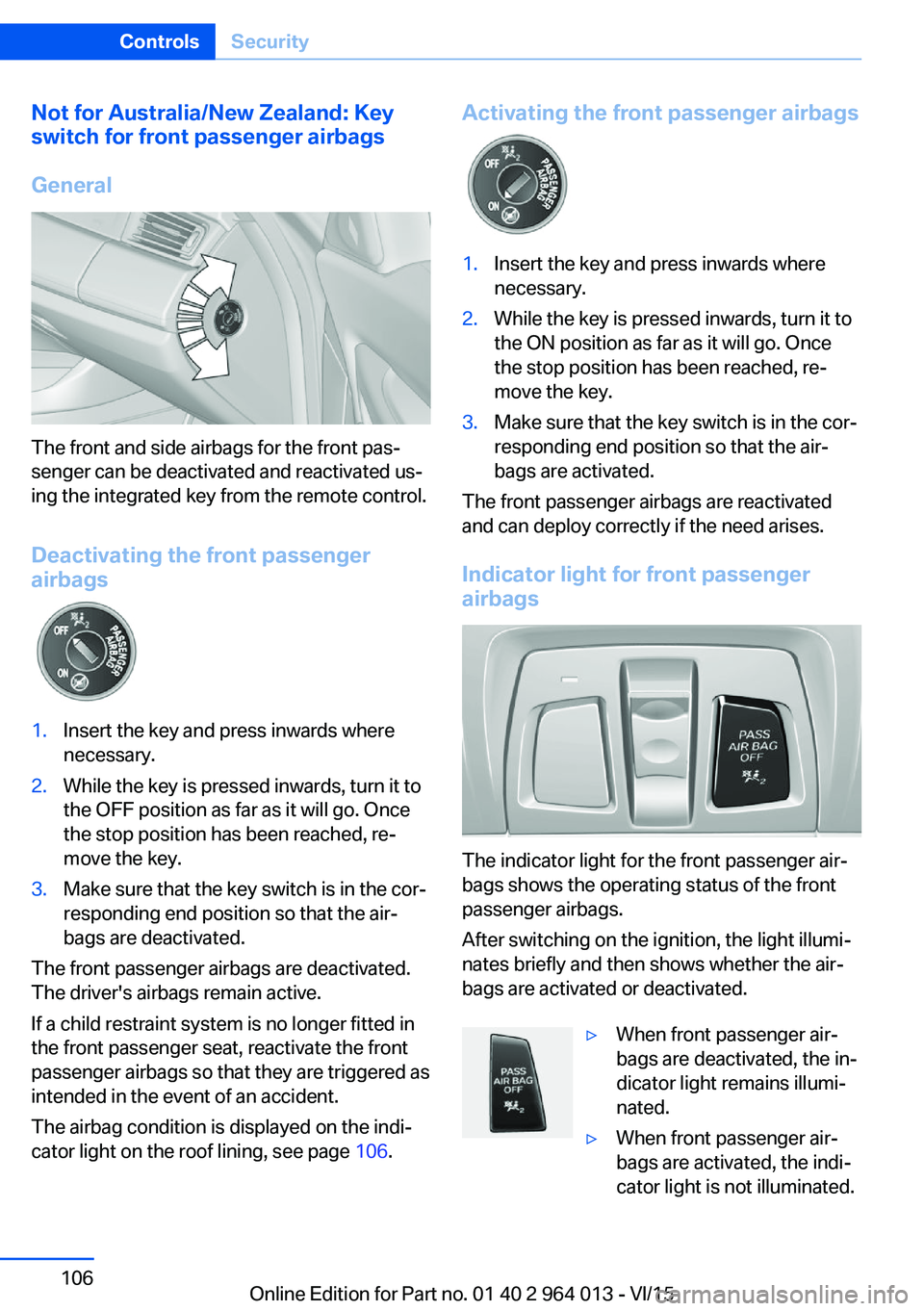
The front and side airbags for the front pas‐
senger can be deactivated and reactivated us‐
ing the integrated key from the remote control.
Deactivating the front passenger
airbags
1.Insert the key and press inwards where
necessary.2.While the key is pressed inwards, turn it to
the OFF position as far as it will go. Once
the stop position has been reached, re‐
move the key.3.Make sure that the key switch is in the cor‐
responding end position so that the air‐
bags are deactivated.
The front passenger airbags are deactivated.
The driver's airbags remain active.
If a child restraint system is no longer fitted in
the front passenger seat, reactivate the front
passenger airbags so that they are triggered as
intended in the event of an accident.
The airbag condition is displayed on the indi‐
cator light on the roof lining, see page 106.
Activating the front passenger airbags1.Insert the key and press inwards where
necessary.2.While the key is pressed inwards, turn it to
the ON position as far as it will go. Once
the stop position has been reached, re‐
move the key.3.Make sure that the key switch is in the cor‐
responding end position so that the air‐
bags are activated.
The front passenger airbags are reactivated
and can deploy correctly if the need arises.
Indicator light for front passenger airbags
The indicator light for the front passenger air‐
bags shows the operating status of the front
passenger airbags.
After switching on the ignition, the light illumi‐
nates briefly and then shows whether the air‐
bags are activated or deactivated.
▷When front passenger air‐
bags are deactivated, the in‐
dicator light remains illumi‐
nated.▷When front passenger air‐
bags are activated, the indi‐
cator light is not illuminated.Seite 106ControlsSecurity106
Online Edition for Part no. 01 40 2 964 013 - VI/15
Page 136 of 228
Display settings
Brightness
With rear-view camera switched on:1. Select the symbol.2.Turn the controller until the desired setting
is reached and press the controller.
Contrast
With rear-view camera switched on:
1. Select the symbol.2.Turn the controller until the desired setting
is reached and press the controller.
System limits
Detection of objects
Very low obstacles and higher, protruding ob‐
jects such as ledges cannot be detected by
the system.
Assistance functions also consider data from
the PDC.
Follow notes in the PDC chapter, see
page 131.
The objects shown on the Control Display may
be closer than they appear. Do not estimate
the distance to objects on the display.
Side View
Principle Side View provides you with an advance view
of crossing traffic at blind entrances. Road users hidden by obstacles at the side are only
detected very late from the driver's seat. In or‐
der to improve the view, two cameras in the
front area of the vehicle scan the area to the
side.
Notes
The camera pictures are shown simultane‐ ously on the Control Display.
WARNING
The system does not take your personal
responsibility from you when you are estimat‐
ing the traffic situation. Danger of accidents. Adapt driving style to the driving conditions.
Additionally, look directly to check the traffic
situation and the area around the vehicle and
intervene actively in the corresponding situa‐ tions.◀
Overview
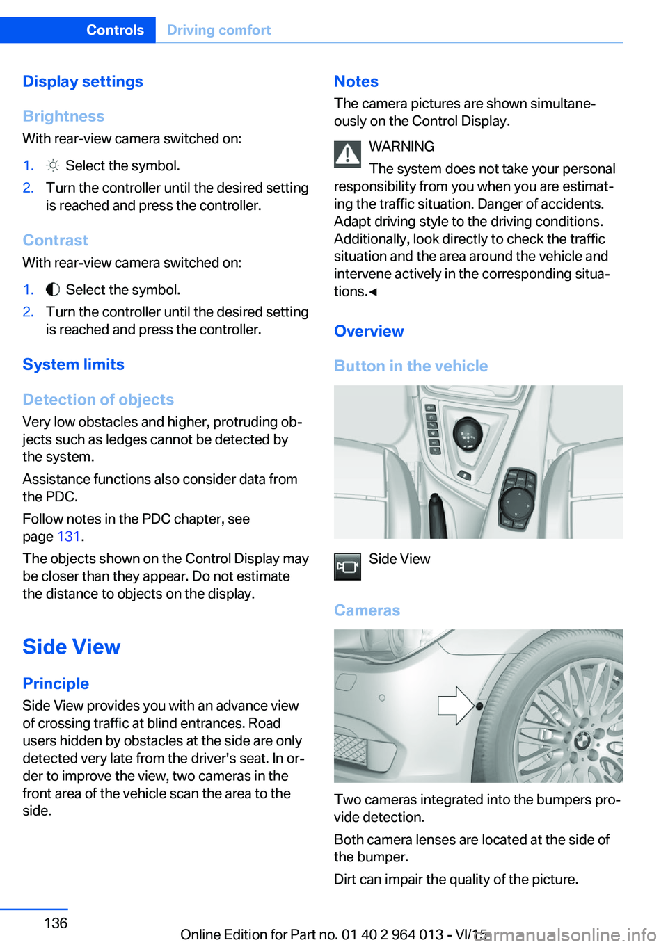
Button in the vehicle
Side View
Cameras
Two cameras integrated into the bumpers pro‐
vide detection.
Both camera lenses are located at the side of
the bumper.
Dirt can impair the quality of the picture.
Seite 136ControlsDriving comfort136
Online Edition for Part no. 01 40 2 964 013 - VI/15
Page 144 of 228
ClimateVehicle equipmentThis chapter describes all standard, national
and special equipment provided in the model
series. Equipment not available in the vehicle is
therefore also described, for example the se‐lected special equipment or national version.
This also applies to safety-relevant functions
and systems. Comply with the relevant na‐
tional regulations when using the correspond‐
ing functions and systems.
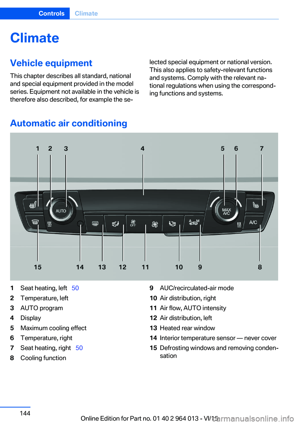
Automatic air conditioning
1Seat heating, left 502Temperature, left3AUTO program4Display5Maximum cooling effect6Temperature, right7Seat heating, right 508Cooling function9AUC/recirculated-air mode10Air distribution, right11Air flow, AUTO intensity12Air distribution, left13Heated rear window14Interior temperature sensor — never cover15Defrosting windows and removing conden‐
sationSeite 144ControlsClimate144
Online Edition for Part no. 01 40 2 964 013 - VI/15