clock BMW M4 2016 Owners Manual
[x] Cancel search | Manufacturer: BMW, Model Year: 2016, Model line: M4, Model: BMW M4 2016Pages: 228, PDF Size: 4.88 MB
Page 20 of 228
▷The system recognises capital and small
letters. To enter small and capital letters
and numbers, it may be necessary to the
change input mode, for example, when
identically writing small and capital letters.
Change between upper/lower case, num‐
bers and symbols, see page 23.▷Enter symbols as they are displayed on the
Control Display.▷Relevant symbols, such as accents or full
stops are always known ambiguously with
the letter. The input option depends on the
language that has been set. You may need
to enter special characters using the Con‐
troller.▷To delete a character, swipe the touchpad
towards the left.▷To enter a space, swipe towards the right
in the middle of the touchpad.▷To enter a hyphen, swipe towards the right
in the upper area of the touchpad.▷To enter an underscore, swipe towards the
right in the lower area of the touchpad.
Operating interactive map and
Internet
The Interactive map of the navigation system
and websites can be moved using the touch‐
pad.
FunctionControlsMove interactive map or
web pages.Swipe in the ap‐
propriate direction.Enlarge/reduce interac‐
tive map or web pages.Pinch or open up
your fingers on the
touchpad.Show menu or open a
link on the Internet.Tap once.
Adjusting the settings
Settings on the Control Display, such as vol‐
ume, for example, can be made using the
touchpad. To do this swipe left or right as ap‐
propriate.
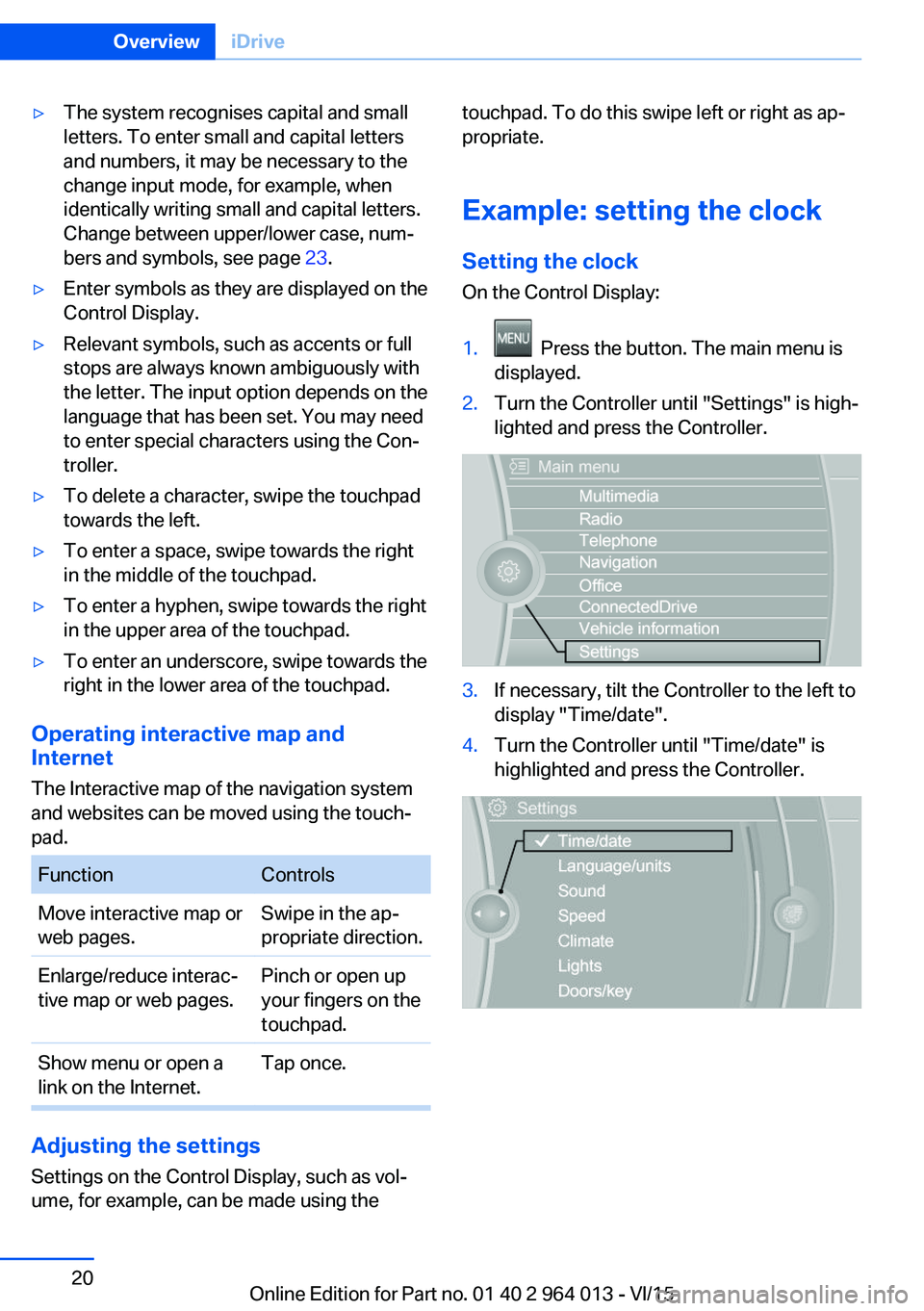
Example: setting the clock Setting the clock
On the Control Display:1. Press the button. The main menu is
displayed.2.Turn the Controller until "Settings" is high‐
lighted and press the Controller.3.If necessary, tilt the Controller to the left to
display "Time/date".4.Turn the Controller until "Time/date" is
highlighted and press the Controller.Seite 20OverviewiDrive20
Online Edition for Part no. 01 40 2 964 013 - VI/15
Page 105 of 228
Notes on optimum protective effect of
the airbag
WARNING
If the seat position is wrong or the de‐
ployment area of the airbag is impaired, the air‐
bag system cannot provide the intended pro‐
tection, or may cause additional injuries when
it deploys. Danger of injury or life. Comply with
these notes for optimum protective effect.◀▷Keep your distance from the airbags.▷Make sure that vehicle occupants keep
their head away from the side airbag.▷Always grip the steering wheel on the
steering wheel rim. Keep you hands in the
3 o'clock and 9 o'clock positions to reduce
the risk of injury to hands or arms when the
airbag deploys.▷Make sure that the front-seat passenger is
sitting correctly, in other words with feet or
legs in the footwell, not resting on the
dashboard.▷Do not position any other persons, pets or
objects between the airbags and persons.▷Never attach any material to the airbag
covers with adhesive; never place material
over them or modify them in any way.▷Keep the dashboard and windscreen in the
area of the passenger's side free, for exam‐
ple do not attach adhesive foil or covers
and do not fit brackets for navigation devi‐
ces or mobile telephones.▷Do not use the front airbag cover on the
front passenger's side as a tray.▷Do not fit seat covers, cushions or other
objects not specifically suitable for seats
with integral side airbags to the front seats.▷Do not hang items of clothing such as
coats or jackets over the backrests.▷Do not modify individual components of
the system or its wiring in any way. This
also applies to the covers of the steering
wheel, the dashboard and seats.▷Do not dismantle the airbag system.
Even if all these notes are complied with, de‐
pending on the circumstances in which an ac‐
cident occurs, certain injuries as a result of
contact with the airbag cannot be entirely ruled
out.
The noise caused by the deployment of an air‐
bag may lead to temporary hearing loss for ve‐
hicle occupants sensitive to noise.
Operational readiness of the airbag
system
Notes WARNING
Individual components of the airbag sys‐
tem can be hot after triggering. Danger of in‐ jury. Do not touch individual components.◀
WARNING
Work carried out incorrectly can lead to a
failure, a malfunction or accidental triggering of
the airbag system. If there is a malfunction, the
airbag system might not trigger as intended in
an accident, in spite of the accident being of
the appropriate severity. Danger of injury or
life. Have the airbag system tested, repaired or
removed and scrapped by a Service Partner or a qualified specialist workshop.◀
Correct function When the ignition is switched on, the
warning light in the instrument cluster
briefly illuminates in order to show the
functional readiness of the entire airbag sys‐
tem and the belt tensioner.
Airbag system disrupted
▷Warning light does not illuminate after the
ignition is switched on.▷Warning lamp is permanently illuminated.Seite 105SecurityControls105
Online Edition for Part no. 01 40 2 964 013 - VI/15
Page 172 of 228
RefuellingVehicle equipmentThis chapter describes all standard, national
and special equipment provided in the model
series. Equipment not available in the vehicle is
therefore also described, for example the se‐
lected special equipment or national version.
This also applies to safety-relevant functions
and systems. Comply with the relevant na‐
tional regulations when using the correspond‐
ing functions and systems.
Notes Before refuelling, observe notes on fuel quality,
see page 174.
ATTENTION
If the range drops below 50 km, approx.
30 miles, the engine could not be supplied
anymore with sufficient fuel. Engine functions
are not ensured anymore. Danger of damage
to property. Refuel in good time.◀
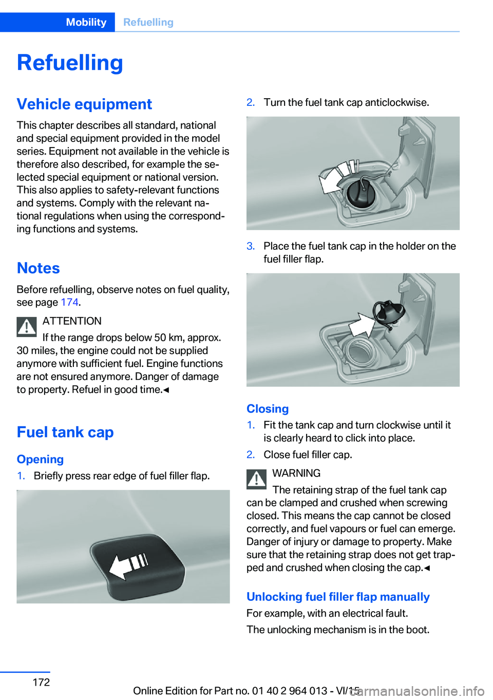
Fuel tank cap Opening1.Briefly press rear edge of fuel filler flap.2.Turn the fuel tank cap anticlockwise.3.Place the fuel tank cap in the holder on the
fuel filler flap.
Closing
1.Fit the tank cap and turn clockwise until it
is clearly heard to click into place.2.Close fuel filler cap.
WARNING
The retaining strap of the fuel tank cap
can be clamped and crushed when screwing
closed. This means the cap cannot be closed
correctly, and fuel vapours or fuel can emerge.
Danger of injury or damage to property. Make
sure that the retaining strap does not get trap‐
ped and crushed when closing the cap.◀
Unlocking fuel filler flap manually
For example, with an electrical fault.
The unlocking mechanism is in the boot.
Seite 172MobilityRefuelling172
Online Edition for Part no. 01 40 2 964 013 - VI/15
Page 187 of 228
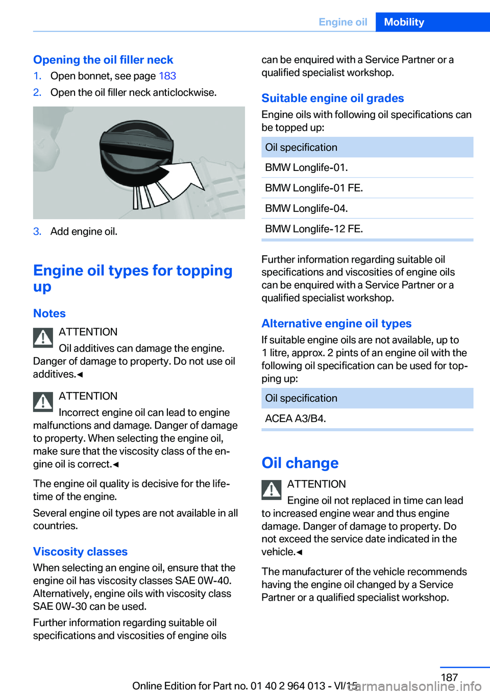
Opening the oil filler neck1.Open bonnet, see page 1832.Open the oil filler neck anticlockwise.3.Add engine oil.
Engine oil types for topping
up
Notes ATTENTION
Oil additives can damage the engine.
Danger of damage to property. Do not use oil
additives.◀
ATTENTION
Incorrect engine oil can lead to engine
malfunctions and damage. Danger of damage
to property. When selecting the engine oil,
make sure that the viscosity class of the en‐
gine oil is correct.◀
The engine oil quality is decisive for the life‐
time of the engine.
Several engine oil types are not available in all
countries.
Viscosity classes When selecting an engine oil, ensure that the
engine oil has viscosity classes SAE 0W-40.
Alternatively, engine oils with viscosity class
SAE 0W-30 can be used.
Further information regarding suitable oil
specifications and viscosities of engine oils
can be enquired with a Service Partner or a
qualified specialist workshop.
Suitable engine oil grades
Engine oils with following oil specifications can
be topped up:Oil specificationBMW Longlife-01.BMW Longlife-01 FE.BMW Longlife-04.BMW Longlife-12 FE.
Further information regarding suitable oil
specifications and viscosities of engine oils
can be enquired with a Service Partner or a
qualified specialist workshop.
Alternative engine oil types If suitable engine oils are not available, up to
1 litre, approx. 2 pints of an engine oil with the
following oil specification can be used for top‐
ping up:
Oil specificationACEA A3/B4.
Oil change
ATTENTION
Engine oil not replaced in time can lead
to increased engine wear and thus engine
damage. Danger of damage to property. Do
not exceed the service date indicated in the
vehicle.◀
The manufacturer of the vehicle recommends
having the engine oil changed by a Service
Partner or a qualified specialist workshop.
Seite 187Engine oilMobility187
Online Edition for Part no. 01 40 2 964 013 - VI/15
Page 189 of 228
CoolantVehicle equipmentThis chapter describes all standard, national
and special equipment provided in the model
series. Equipment not available in the vehicle is
therefore also described, for example the se‐
lected special equipment or national version.
This also applies to safety-relevant functions
and systems. Comply with the relevant na‐
tional regulations when using the correspond‐
ing functions and systems.
General
The vehicle has two coolant tanks located in
the engine compartment.
To guarantee operational safety of the vehicle,
always check the coolant levels of both coolant
tanks.
Notes WARNING
If the cooling system is opened when the
engine is hot, coolant can escape and cause
scalds. Danger of injury. Only open the cooling
system when the engine has cooled down.◀
WARNING
Additives are harmful to health and incor‐
rect additives can damage the engine. Danger
of injury and damage to property. Do not allow
additives to come into contact with clothing,
skin or eyes, and do not swallow them. Only
use suitable additives.◀
Coolant is a mixture of water and an additive.
Not all commercially available additives are
suitable for the vehicle. Information regarding
suitable additives is available from a Service
Partner or a qualified specialist workshop.Coolant level
Overview
Depending on the engine version, the coolant
tank is located on the right or left of the engine
compartment.
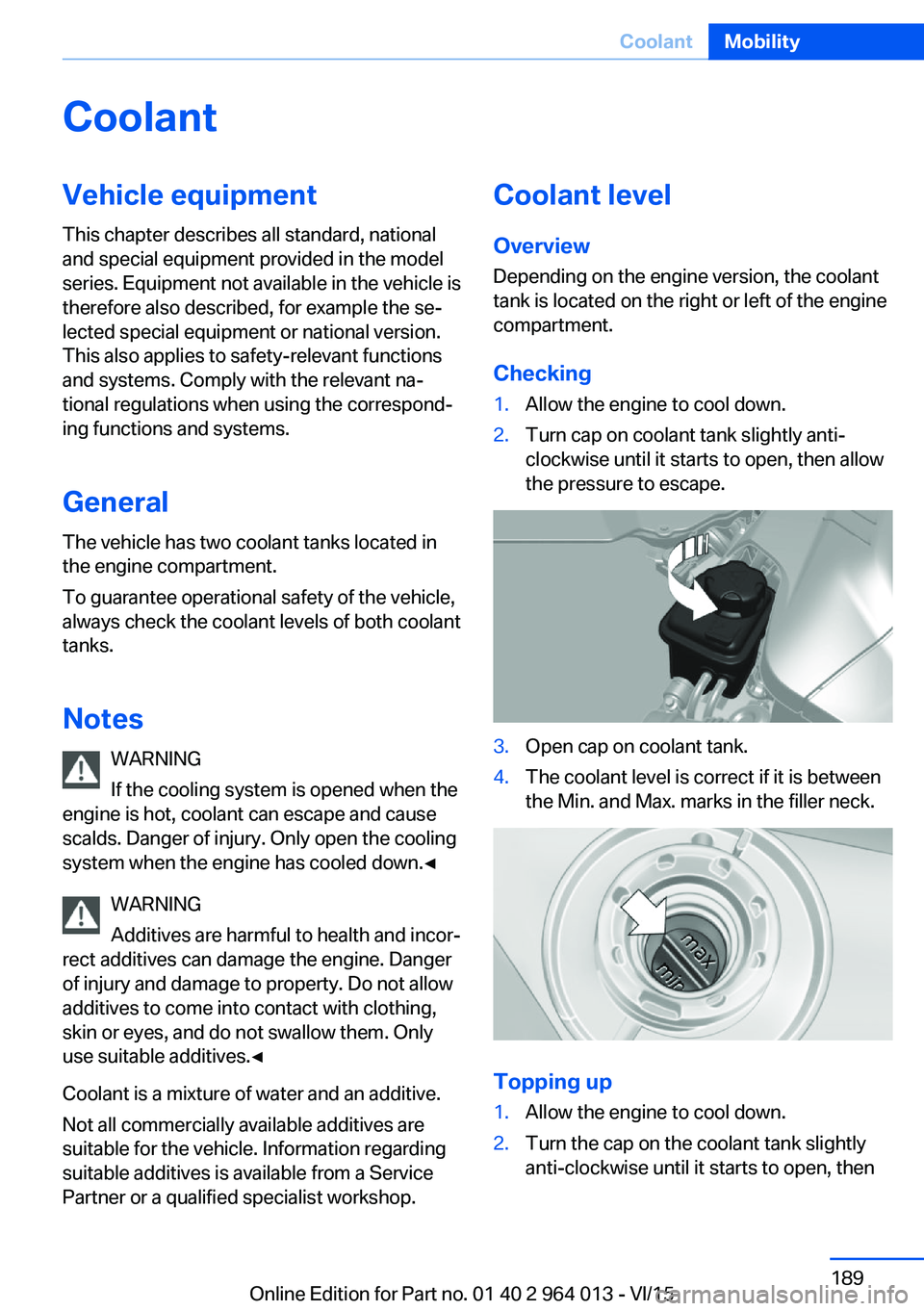
Checking1.Allow the engine to cool down.2.Turn cap on coolant tank slightly anti-
clockwise until it starts to open, then allow
the pressure to escape.3.Open cap on coolant tank.4.The coolant level is correct if it is between
the Min. and Max. marks in the filler neck.
Topping up
1.Allow the engine to cool down.2.Turn the cap on the coolant tank slightly
anti-clockwise until it starts to open, thenSeite 189CoolantMobility189
Online Edition for Part no. 01 40 2 964 013 - VI/15
Page 195 of 228
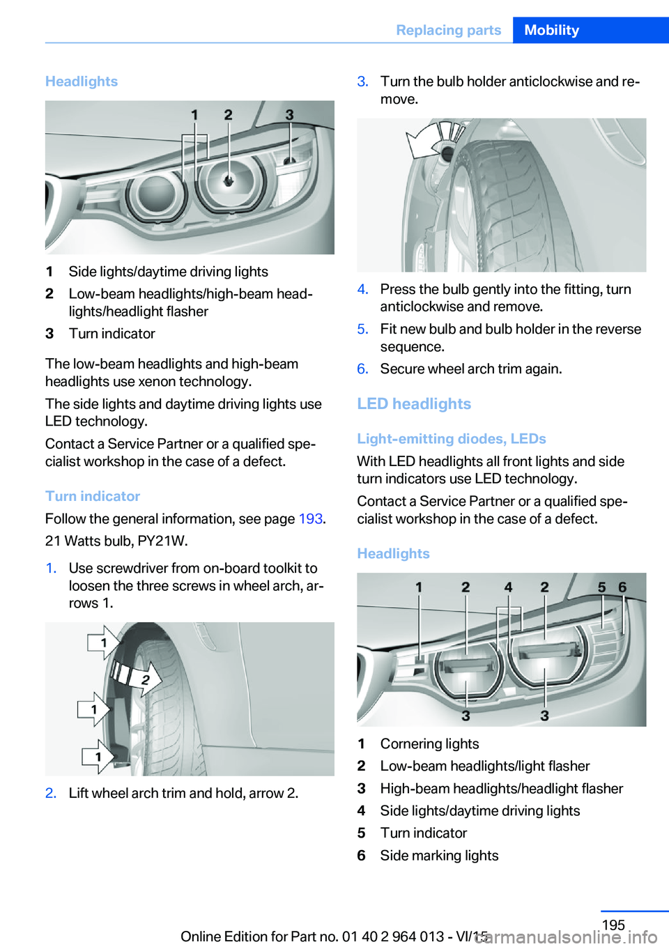
Headlights1Side lights/daytime driving lights2Low-beam headlights/high-beam head‐
lights/headlight flasher3Turn indicator
The low-beam headlights and high-beam
headlights use xenon technology.
The side lights and daytime driving lights use
LED technology.
Contact a Service Partner or a qualified spe‐
cialist workshop in the case of a defect.
Turn indicator
Follow the general information, see page 193.
21 Watts bulb, PY21W.
1.Use screwdriver from on-board toolkit to
loosen the three screws in wheel arch, ar‐
rows 1.2.Lift wheel arch trim and hold, arrow 2.3.Turn the bulb holder anticlockwise and re‐
move.4.Press the bulb gently into the fitting, turn
anticlockwise and remove.5.Fit new bulb and bulb holder in the reverse
sequence.6.Secure wheel arch trim again.
LED headlights
Light-emitting diodes, LEDs
With LED headlights all front lights and side
turn indicators use LED technology.
Contact a Service Partner or a qualified spe‐
cialist workshop in the case of a defect.
Headlights
1Cornering lights2Low-beam headlights/light flasher3High-beam headlights/headlight flasher4Side lights/daytime driving lights5Turn indicator6Side marking lightsSeite 195Replacing partsMobility195
Online Edition for Part no. 01 40 2 964 013 - VI/15
Page 197 of 228
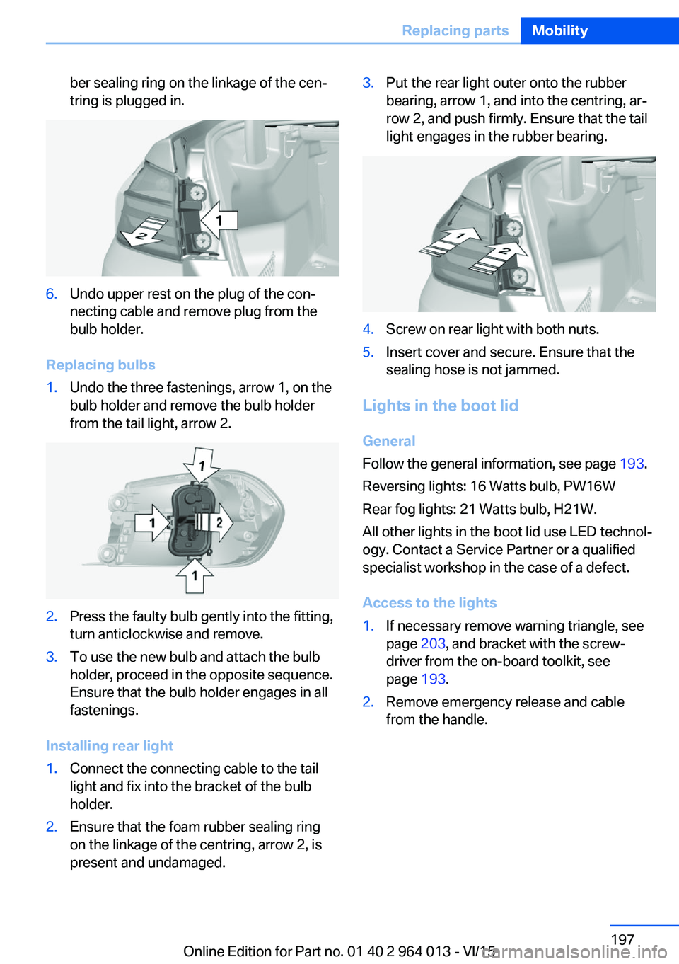
ber sealing ring on the linkage of the cen‐
tring is plugged in.6.Undo upper rest on the plug of the con‐
necting cable and remove plug from the
bulb holder.
Replacing bulbs
1.Undo the three fastenings, arrow 1, on the
bulb holder and remove the bulb holder
from the tail light, arrow 2.2.Press the faulty bulb gently into the fitting,
turn anticlockwise and remove.3.To use the new bulb and attach the bulb
holder, proceed in the opposite sequence.
Ensure that the bulb holder engages in all
fastenings.
Installing rear light
1.Connect the connecting cable to the tail
light and fix into the bracket of the bulb
holder.2.Ensure that the foam rubber sealing ring
on the linkage of the centring, arrow 2, is
present and undamaged.3.Put the rear light outer onto the rubber
bearing, arrow 1, and into the centring, ar‐
row 2, and push firmly. Ensure that the tail
light engages in the rubber bearing.4.Screw on rear light with both nuts.5.Insert cover and secure. Ensure that the
sealing hose is not jammed.
Lights in the boot lid
General
Follow the general information, see page 193.
Reversing lights: 16 Watts bulb, PW16W
Rear fog lights: 21 Watts bulb, H21W.
All other lights in the boot lid use LED technol‐
ogy. Contact a Service Partner or a qualified
specialist workshop in the case of a defect.
Access to the lights
1.If necessary remove warning triangle, see
page 203, and bracket with the screw‐
driver from the on-board toolkit, see
page 193.2.Remove emergency release and cable
from the handle.Seite 197Replacing partsMobility197
Online Edition for Part no. 01 40 2 964 013 - VI/15
Page 198 of 228
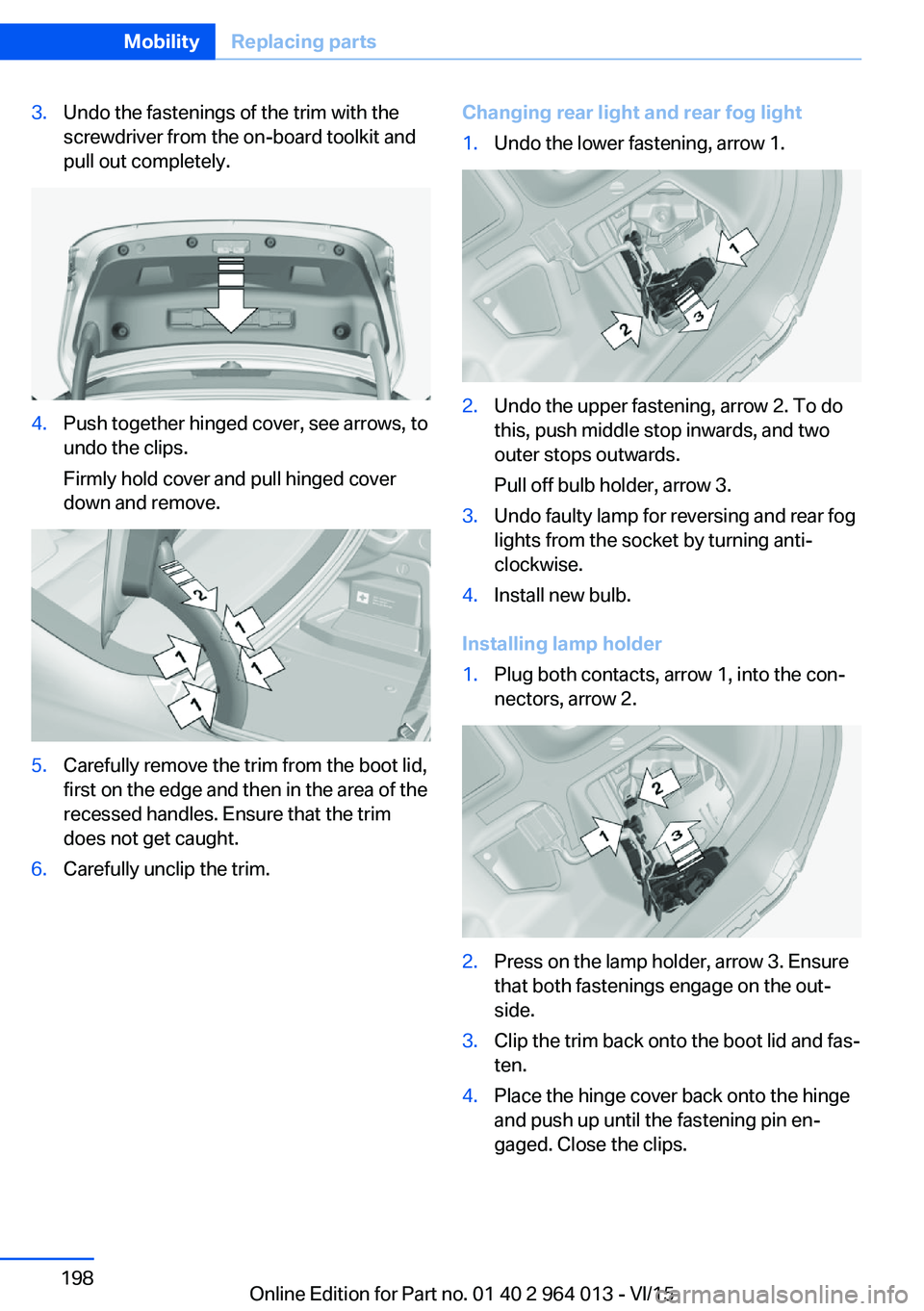
3.Undo the fastenings of the trim with the
screwdriver from the on-board toolkit and
pull out completely.4.Push together hinged cover, see arrows, to
undo the clips.
Firmly hold cover and pull hinged cover
down and remove.5.Carefully remove the trim from the boot lid,
first on the edge and then in the area of the
recessed handles. Ensure that the trim
does not get caught.6.Carefully unclip the trim.Changing rear light and rear fog light1.Undo the lower fastening, arrow 1.2.Undo the upper fastening, arrow 2. To do
this, push middle stop inwards, and two
outer stops outwards.
Pull off bulb holder, arrow 3.3.Undo faulty lamp for reversing and rear fog
lights from the socket by turning anti-
clockwise.4.Install new bulb.
Installing lamp holder
1.Plug both contacts, arrow 1, into the con‐
nectors, arrow 2.2.Press on the lamp holder, arrow 3. Ensure
that both fastenings engage on the out‐
side.3.Clip the trim back onto the boot lid and fas‐
ten.4.Place the hinge cover back onto the hinge
and push up until the fastening pin en‐
gaged. Close the clips.Seite 198MobilityReplacing parts198
Online Edition for Part no. 01 40 2 964 013 - VI/15
Page 219 of 228
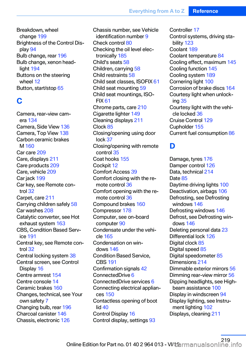
Breakdown, wheelchange 199
Brightness of the Control Dis‐ play 94
Bulb change, rear 196
Bulb change, xenon head‐ light 194
Buttons on the steering wheel 12
Button, start/stop 65
C
Camera, rear-view cam‐ era 134
Camera, Side View 136
Camera, Top View 138
Carbon ceramic brakes M 160
Car care 209
Care, displays 211
Care products 209
Care, vehicle 209
Car jack 199
Car key, see Remote con‐ trol 32
Carpet, care 211
Carrying children safely 58
Car washes 208
Catalytic converter, see Hot exhaust system 163
CBS, Condition Based Serv‐ ice 191
Central key, see Remote con‐ trol 32
Central locking system 38
Central screen, see Control Display 16
Centre armrest 154
Centre console 14
Ceramic brakes 160
Changes, technical, see Your own safety 7
Changing bulb, rear 196
Charcoal canister 146
Chassis, electronic 126 Chassis number, see Vehicle
identification number 9
Check control 80
Checking the oil level elec‐ tronically 185
Child's seats 58
Children, carrying 58
Child restraints 58
Child seat classes, ISOFIX 61
Child seat mounting 59
Child seat mountings, ISO‐ FIX 61
Chrome parts, care 210
Cigarette lighter 149
Cleaning displays 211
Clock 85
Closing/opening using door lock 37
Closing/opening with remote control 35
Coat hooks 155
Cockpit 12
Comfort Access 39
Comfort closing with the re‐ mote control 36
Comfort opening with the re‐ mote control 36
Compound brakes 160
Compressor 178
Computer, see on-board computer 90
Condensate under the vehi‐ cle 165
Condensation on win‐ dows 146
Condition Based Service, CBS 191
Confirmation signals 42
ConnectedDrive 6
ConnectedDrive services 6
Connecting electrical applian‐ ces 150
Contactless opening of boot lid 40
Control Display 16
Control display, settings 93 Controller 17
Control systems, driving sta‐ bility 123
Coolant 189
Coolant temperature 84
Cooling effect, maximum 145
Cooling function 145
Cooling system 189
Cornering light 100
Corrosion of brake discs 164
Courtesy light when unlock‐ ing 35
Courtesy light with the vehi‐ cle locked 36
Cruise Control 129
Cupholder 155
Current fuel consumption 86
D
Damage, tyres 176
Damper control 126
Data, technical 214
Date 85
Daytime driving lights 100
Deactivation, airbags 106
Defrosting, see Defrosting windows 146
Defrosting windows 146
Defrost, see Defrosting win‐ dows 146
Deleting personal data 23
Differential lock 126
Digital clock 85
Digital speed 85
Digital speedometer 85
Dimensions 214
Dimmable exterior mirrors 56
Dimming rear-view mirror 56
Dipping headlights, see High- beam assistance 100
Display in windscreen 94
Display lighting, see Instru‐ ment lighting 102
Displays, cleaning 211 Seite 219Everything from A to ZReference219
Online Edition for Part no. 01 40 2 964 013 - VI/15