height BMW M4 2016 Owners Manual
[x] Cancel search | Manufacturer: BMW, Model Year: 2016, Model line: M4, Model: BMW M4 2016Pages: 228, PDF Size: 4.88 MB
Page 33 of 228
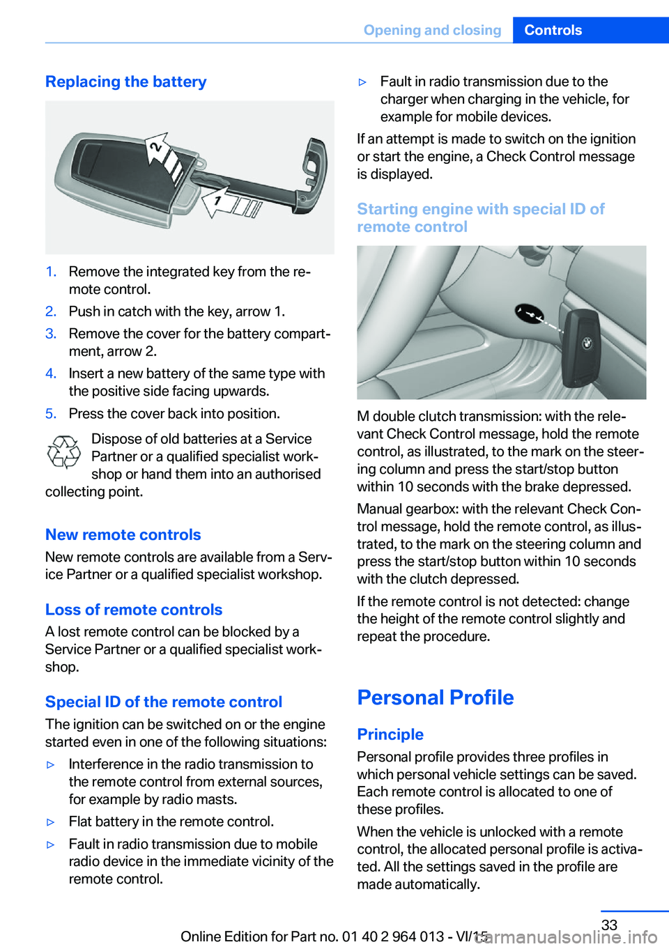
Replacing the battery1.Remove the integrated key from the re‐
mote control.2.Push in catch with the key, arrow 1.3.Remove the cover for the battery compart‐
ment, arrow 2.4.Insert a new battery of the same type with
the positive side facing upwards.5.Press the cover back into position.
Dispose of old batteries at a Service
Partner or a qualified specialist work‐
shop or hand them into an authorised
collecting point.
New remote controlsNew remote controls are available from a Serv‐
ice Partner or a qualified specialist workshop.
Loss of remote controls
A lost remote control can be blocked by a
Service Partner or a qualified specialist work‐
shop.
Special ID of the remote control The ignition can be switched on or the engine
started even in one of the following situations:
▷Interference in the radio transmission to
the remote control from external sources,
for example by radio masts.▷Flat battery in the remote control.▷Fault in radio transmission due to mobile
radio device in the immediate vicinity of the
remote control.▷Fault in radio transmission due to the
charger when charging in the vehicle, for
example for mobile devices.
If an attempt is made to switch on the ignition
or start the engine, a Check Control message
is displayed.
Starting engine with special ID ofremote control
M double clutch transmission: with the rele‐
vant Check Control message, hold the remote
control, as illustrated, to the mark on the steer‐
ing column and press the start/stop button
within 10 seconds with the brake depressed.
Manual gearbox: with the relevant Check Con‐
trol message, hold the remote control, as illus‐
trated, to the mark on the steering column and
press the start/stop button within 10 seconds
with the clutch depressed.
If the remote control is not detected: change
the height of the remote control slightly and
repeat the procedure.
Personal Profile
Principle Personal profile provides three profiles in
which personal vehicle settings can be saved.
Each remote control is allocated to one of
these profiles.
When the vehicle is unlocked with a remote
control, the allocated personal profile is activa‐
ted. All the settings saved in the profile are
made automatically.
Seite 33Opening and closingControls33
Online Edition for Part no. 01 40 2 964 013 - VI/15
Page 48 of 228
AdjustingVehicle equipment
This chapter describes all standard, national
and special equipment provided in the model
series. Equipment not available in the vehicle is
therefore also described, for example the se‐
lected special equipment or national version.
This also applies to safety-relevant functions
and systems. Comply with the relevant na‐
tional regulations when using the correspond‐
ing functions and systems.
Safe seated position A seated position that suitably reflects your re‐
quirements is a vital condition of relaxed driv‐
ing with a minimum of fatigue.
In the event of an accident, the seated position
plays an important role together with:▷Seat belts, see page 52.▷Head restraints, see page 54.▷Airbags, see page 104.
Seats
Notes WARNING
Seat adjustment during the journey can
lead to unexpected seat movements. You
could lose control of the vehicle. Danger of ac‐
cidents. Only adjust the seat on the driver side
when at a standstill.◀
WARNING
If the seat backrest is angled back too
far, the protective effect of the seat belt will no
longer be guaranteed. There is a danger of
slipping under the seat belt in the event of an
accident. Danger of injury or life. Set the seat
before starting the journey. Place the seat
backrest in the most upright possible position,
and do not change it during the journey.◀
WARNING
Danger of trapping when moving the
seats. Danger of injury or damage to property.
Before making the setting, make sure that the
movement area of the seat is clear.◀
Manually adjustable seats
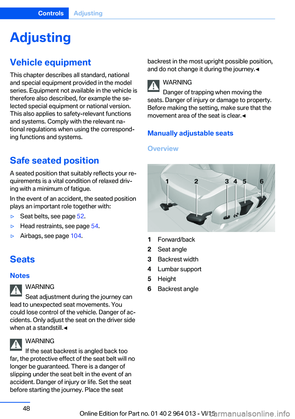
Overview1Forward/back2Seat angle3Backrest width4Lumbar support5Height6Backrest angleSeite 48ControlsAdjusting48
Online Edition for Part no. 01 40 2 964 013 - VI/15
Page 49 of 228
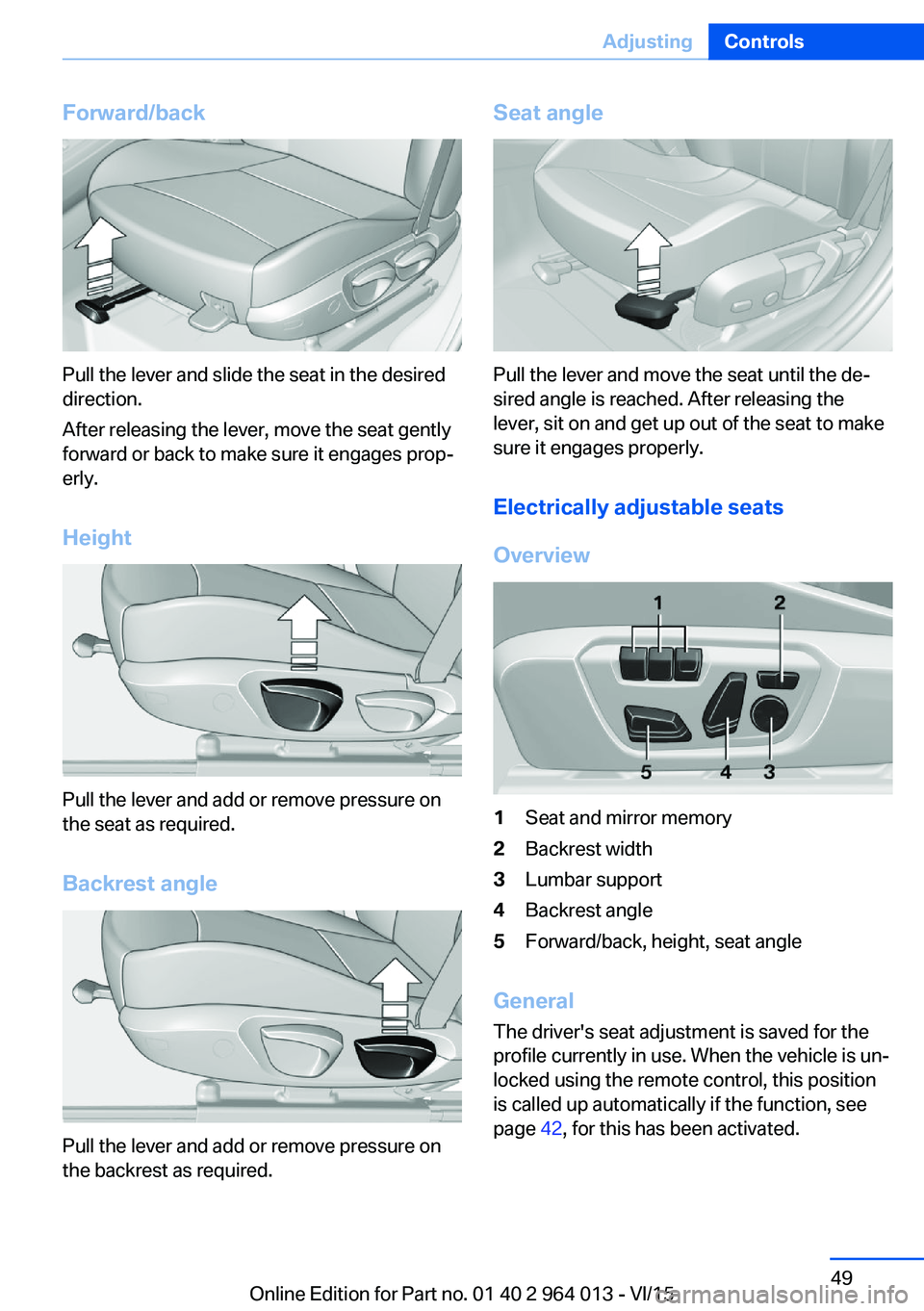
Forward/back
Pull the lever and slide the seat in the desired
direction.
After releasing the lever, move the seat gently
forward or back to make sure it engages prop‐
erly.
Height
Pull the lever and add or remove pressure on
the seat as required.
Backrest angle
Pull the lever and add or remove pressure on
the backrest as required.
Seat angle
Pull the lever and move the seat until the de‐
sired angle is reached. After releasing the
lever, sit on and get up out of the seat to make
sure it engages properly.
Electrically adjustable seats
Overview
1Seat and mirror memory2Backrest width3Lumbar support4Backrest angle5Forward/back, height, seat angle
General The driver's seat adjustment is saved for the
profile currently in use. When the vehicle is un‐
locked using the remote control, this position is called up automatically if the function, see
page 42, for this has been activated.
Seite 49AdjustingControls49
Online Edition for Part no. 01 40 2 964 013 - VI/15
Page 50 of 228
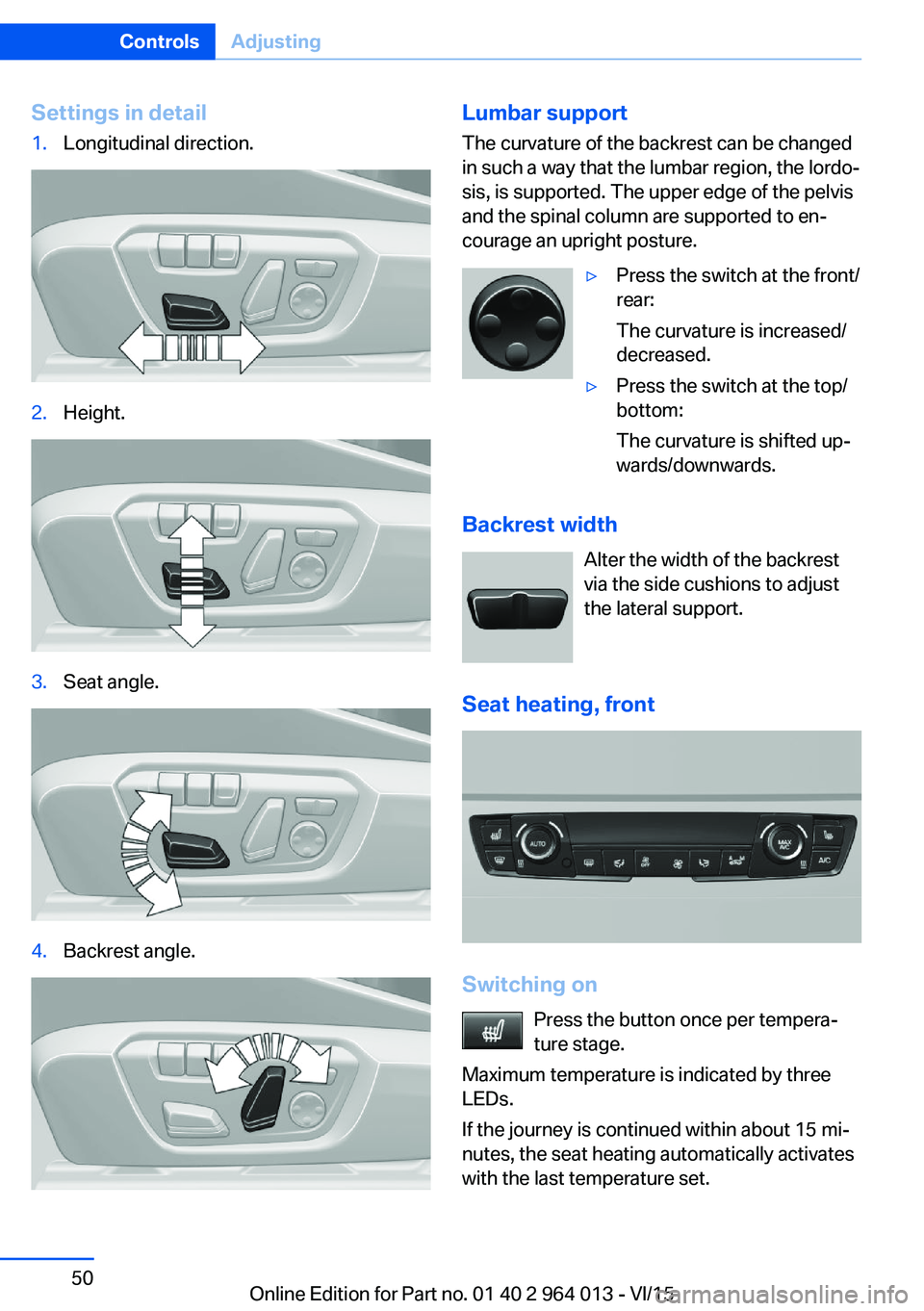
Settings in detail1.Longitudinal direction.2.Height.3.Seat angle.4.Backrest angle.Lumbar support
The curvature of the backrest can be changed
in such a way that the lumbar region, the lordo‐
sis, is supported. The upper edge of the pelvis
and the spinal column are supported to en‐
courage an upright posture.▷Press the switch at the front/
rear:
The curvature is increased/
decreased.▷Press the switch at the top/
bottom:
The curvature is shifted up‐
wards/downwards.
Backrest width
Alter the width of the backrest
via the side cushions to adjust
the lateral support.
Seat heating, front
Switching on Press the button once per tempera‐
ture stage.
Maximum temperature is indicated by three
LEDs.
If the journey is continued within about 15 mi‐
nutes, the seat heating automatically activates
with the last temperature set.
Seite 50ControlsAdjusting50
Online Edition for Part no. 01 40 2 964 013 - VI/15
Page 57 of 228
Steering wheel
Note WARNING
Steering wheel adjustment during the
journey can lead to unexpected steering wheel
movements. You could lose control of the vehi‐
cle. Danger of accidents. Only adjust the steer‐
ing wheel when the vehicle is at a standstill.◀
Electric steering wheel lock With manual gearbox: The steering wheel
locks automatically when the driver's door is
opened.
Switch on ignition to unlock.
WARNING
If steering wheel lock is activated, the ve‐
hicle cannot be steered. Danger of accidents.
Switch on the ignition prior to moving the vehi‐
cle.◀
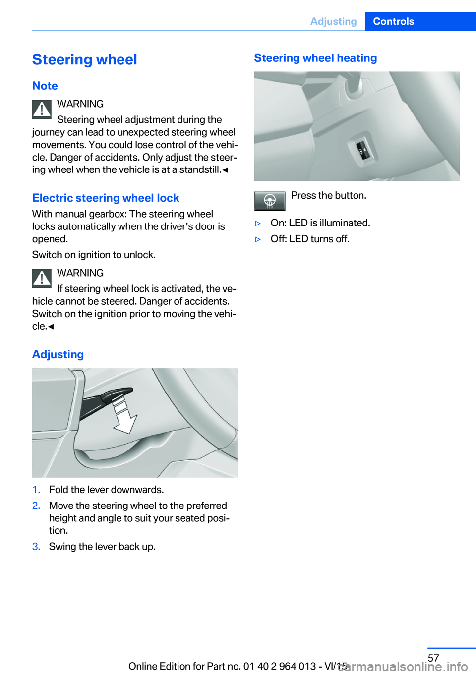
Adjusting1.Fold the lever downwards.2.Move the steering wheel to the preferred
height and angle to suit your seated posi‐
tion.3.Swing the lever back up.Steering wheel heating
Press the button.
▷On: LED is illuminated.▷Off: LED turns off.Seite 57AdjustingControls57
Online Edition for Part no. 01 40 2 964 013 - VI/15
Page 59 of 228
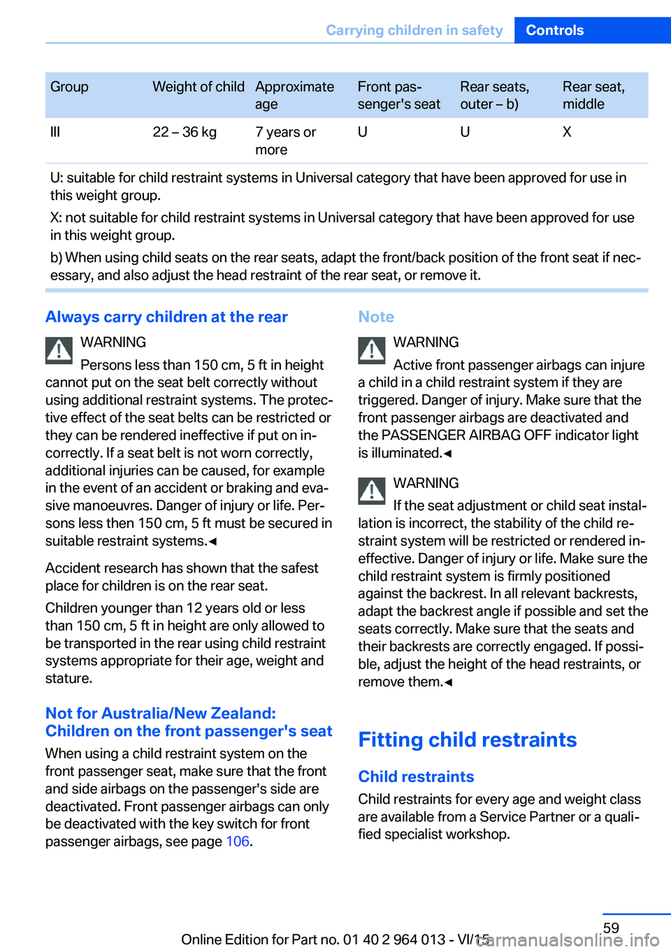
GroupWeight of childApproximate
ageFront pas‐
senger's seatRear seats,
outer – b)Rear seat,
middleIII22 – 36 kg7 years or
moreUUXU: suitable for child restraint systems in Universal category that have been approved for use in
this weight group.
X: not suitable for child restraint systems in Universal category that have been approved for use
in this weight group.
b) When using child seats on the rear seats, adapt the front/back position of the front seat if nec‐
essary, and also adjust the head restraint of the rear seat, or remove it.Always carry children at the rear
WARNING
Persons less than 150 cm, 5 ft in height
cannot put on the seat belt correctly without
using additional restraint systems. The protec‐
tive effect of the seat belts can be restricted or
they can be rendered ineffective if put on in‐
correctly. If a seat belt is not worn correctly,
additional injuries can be caused, for example
in the event of an accident or braking and eva‐
sive manoeuvres. Danger of injury or life. Per‐
sons less then 150 cm, 5 ft must be secured in
suitable restraint systems.◀
Accident research has shown that the safest
place for children is on the rear seat.
Children younger than 12 years old or less
than 150 cm, 5 ft in height are only allowed to
be transported in the rear using child restraint
systems appropriate for their age, weight and
stature.
Not for Australia/New Zealand:
Children on the front passenger's seat
When using a child restraint system on the
front passenger seat, make sure that the front
and side airbags on the passenger's side are
deactivated. Front passenger airbags can only
be deactivated with the key switch for front
passenger airbags, see page 106.Note
WARNING
Active front passenger airbags can injure
a child in a child restraint system if they are
triggered. Danger of injury. Make sure that the
front passenger airbags are deactivated and
the PASSENGER AIRBAG OFF indicator light
is illuminated.◀
WARNING
If the seat adjustment or child seat instal‐
lation is incorrect, the stability of the child re‐
straint system will be restricted or rendered in‐
effective. Danger of injury or life. Make sure the
child restraint system is firmly positioned
against the backrest. In all relevant backrests,
adapt the backrest angle if possible and set the
seats correctly. Make sure that the seats and
their backrests are correctly engaged. If possi‐
ble, adjust the height of the head restraints, or
remove them.◀
Fitting child restraints Child restraintsChild restraints for every age and weight class
are available from a Service Partner or a quali‐
fied specialist workshop.Seite 59Carrying children in safetyControls59
Online Edition for Part no. 01 40 2 964 013 - VI/15
Page 60 of 228
Notes
When selecting, installing and using child re‐
straint systems, comply with the information
provided by the manufacturer of the child re‐
straint system.
WARNING
If child restraint systems and their at‐
tachment systems have been damaged or sub‐
jected to stresses in an accident, their protec‐
tive function may be restricted or rendered
ineffective. A child might not be adequately re‐
strained, for example, in the event of an acci‐
dent or braking and evasive manoeuvres. Dan‐
ger of injury or life. If child restraint systems
and their attachment systems have been dam‐
aged or subjected to stresses in an accident,
have them checked by the Service Partner or a
qualified specialist workshop and renewed if
necessary.◀
WARNING
If the seat adjustment or child seat instal‐
lation is incorrect, the stability of the child re‐
straint system will be restricted or rendered in‐
effective. Danger of injury or life. Make sure the
child restraint system is firmly positioned
against the backrest. In all relevant backrests,
adapt the backrest angle if possible and set the
seats correctly. Make sure that the seats and
their backrests are correctly engaged. If possi‐
ble, adjust the height of the head restraints, or
remove them.◀
For Australia/New Zealand:
installation of child restraints
Please note the following warning because
your vehicle has been equipped with a front
airbag for the front passenger's seat that can‐
not be deactivated:
It is recommended not to use any kindof child restraint system on the front
passenger's seat.Extreme hazard
Do not use a rearward facing child re‐
straint on a seat protected by an airbag in front
of it.◀
Not for Australia/New Zealand: On the
front passenger's seat
Deactivating airbags WARNING
Active front passenger airbags can injure
a child in a child restraint system if they are triggered. Danger of injury. Make sure that the
front passenger airbags are deactivated and
the PASSENGER AIRBAG OFF indicator light
is illuminated.◀
Before fitting a child restraint in the front pas‐
senger's seat, make sure that the front and
side airbags on the passenger's side are disa‐
bled.
Deactivating the front passenger airbags with
key switch, see page 106.
Rear-facing child restraints DANGER
Active front passenger airbags can fatally
injure a child in a rearward-facing child re‐
straint system if they are triggered. Danger of
injury or life. Make sure that the front passen‐
ger airbags are deactivated and the PASSEN‐
GER AIRBAG OFF indicator light is illumina‐
ted.◀Seite 60ControlsCarrying children in safety60
Online Edition for Part no. 01 40 2 964 013 - VI/15
Page 61 of 228
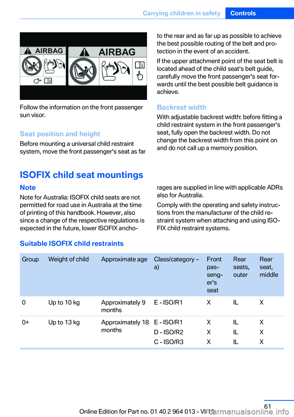
Follow the information on the front passenger
sun visor.
Seat position and height
Before mounting a universal child restraint
system, move the front passenger's seat as far
to the rear and as far up as possible to achieve
the best possible routing of the belt and pro‐
tection in the event of an accident.
If the upper attachment point of the seat belt is
located ahead of the child seat's belt guide,
carefully move the front passenger's seat for‐
wards until the best possible belt guidance is
achieve.
Backrest width With adjustable backrest width: before fitting a
child restraint system in the front passenger's
seat, fully open the backrest width. Do not
change the backrest width from this point on
and do not call up a memory position.
ISOFIX child seat mountings
Note
Note for Australia: ISOFIX child seats are not
permitted for road use in Australia at the time
of printing of this handbook. However, also
since a change of the respective regulations is
expected in the future, lower ISOFIX ancho‐rages are supplied in line with applicable ADRs
also for Australia.
Comply with the operating and safety instruc‐
tions from the manufacturer of the child re‐
straint system when attaching and using ISO‐
FIX child restraint systems.
Suitable ISOFIX child restraints
GroupWeight of childApproximate ageClass/category –
a)Front
pas‐
seng‐
er's
seatRear
seats,
outerRear
seat,
middle0Up to 10 kgApproximately 9
monthsE - ISO/R1XILX0+Up to 13 kgApproximately 18
monthsE - ISO/R1
D - ISO/R2
C - ISO/R3X
X
XIL
IL
ILX
X
XSeite 61Carrying children in safetyControls61
Online Edition for Part no. 01 40 2 964 013 - VI/15
Page 95 of 228
Switching on/off1."Settings"2."Head-up display"3."Head-up display"
Display
Standard view The following information is displayed in the
Head-Up Display:
▷Speed.▷Navigation system.▷Check Control messages.▷Selection list from the instrument cluster.▷Driver Assistance Systems.
Some of this information is only shown briefly
when needed.
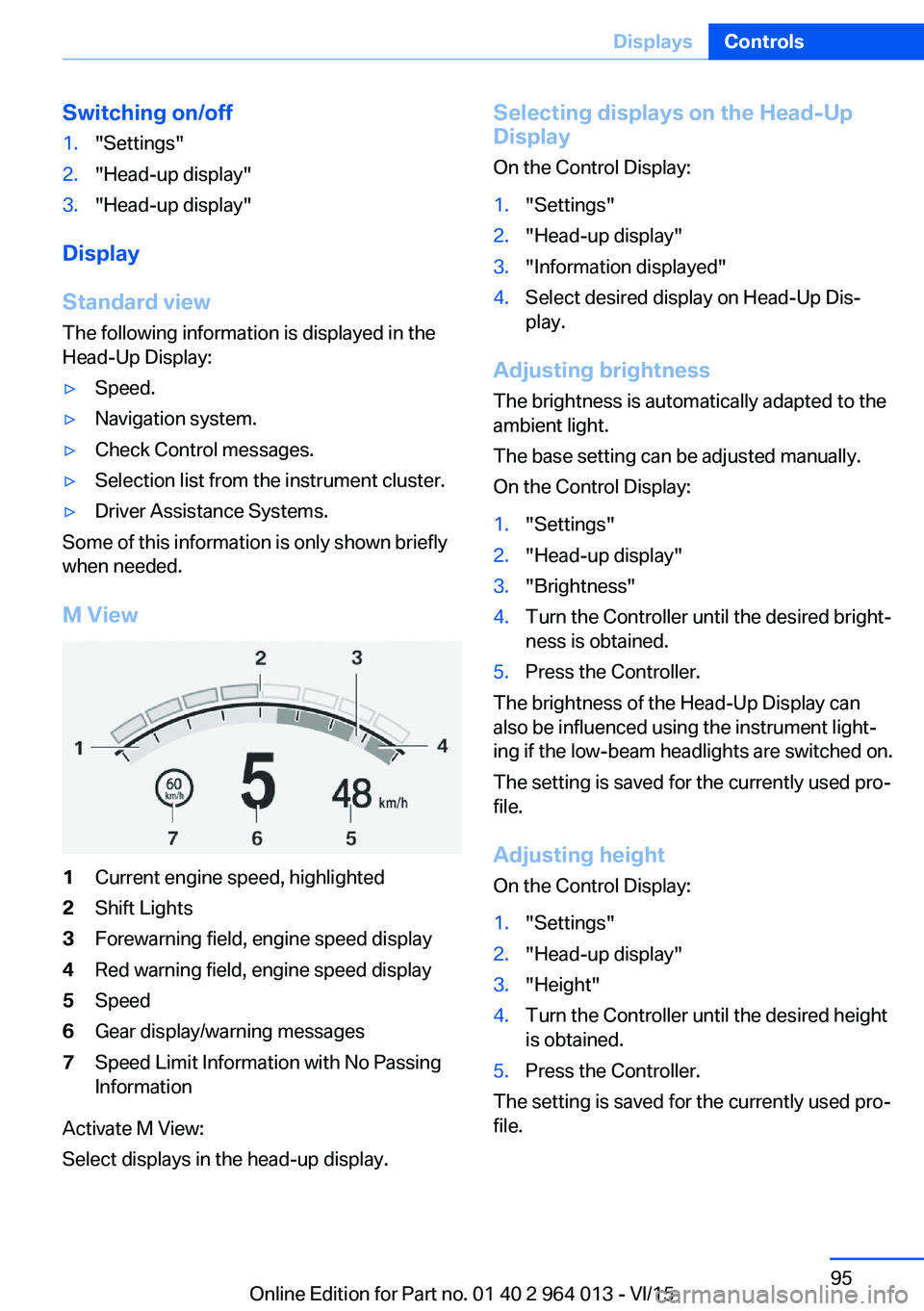
M View
1Current engine speed, highlighted2Shift Lights3Forewarning field, engine speed display4Red warning field, engine speed display5Speed6Gear display/warning messages7Speed Limit Information with No Passing
Information
Activate M View:
Select displays in the head-up display.
Selecting displays on the Head-Up
Display
On the Control Display:1."Settings"2."Head-up display"3."Information displayed"4.Select desired display on Head-Up Dis‐
play.
Adjusting brightness
The brightness is automatically adapted to the
ambient light.
The base setting can be adjusted manually.
On the Control Display:
1."Settings"2."Head-up display"3."Brightness"4.Turn the Controller until the desired bright‐
ness is obtained.5.Press the Controller.
The brightness of the Head-Up Display can
also be influenced using the instrument light‐
ing if the low-beam headlights are switched on.
The setting is saved for the currently used pro‐
file.
Adjusting height
On the Control Display:
1."Settings"2."Head-up display"3."Height"4.Turn the Controller until the desired height
is obtained.5.Press the Controller.
The setting is saved for the currently used pro‐
file.
Seite 95DisplaysControls95
Online Edition for Part no. 01 40 2 964 013 - VI/15
Page 115 of 228
Warning with braking function
Display
If there is a risk of collision with a detected per‐
son, a warning symbol is shown in the instru‐
ment cluster and in the head-up display.
Red symbol is displayed and an acous‐
tic warning sounds.
Take action yourself immediately, by braking
or swerving.
Brake intervention
The warning requires to take action yourself.
Maximum braking force is used during a warn‐
ing. In order for braking force support to be
used, it is necessary for the brake to be
pressed sufficiently quickly and powerfully. In
addition, the system may also support with a
small amount of braking if there is the risk of a
collision. The vehicle can be braked at low
speed until it comes to a stop.
Manual gearbox: When brakes are engaged
until it comes to a stop, the engine may shut
off.
There will only be brake intervention if Dy‐
namic Stability Control, DSC is activated and
M Dynamic Mode MDM is not activated.
Braking can be discontinued either by pressing
the accelerator pedal or by actively moving the
steering wheel.
Detection of objects can be restricted. Limita‐
tions of the detection range and functional re‐
strictions are to be considered.
System limits
Detection range
The detection capacity of the camera is limi‐
ted.
This is why it can occur that no warnings are
issued or they are issued late.
It is possible that the following are not detec‐
ted:▷Partially concealed pedestrians.▷Pedestrians who are not detected as such
because of the viewing angle or contour.▷Pedestrians outside the detection range.▷Pedestrians under a height of approxi‐
mately 80 cm, 32 in.
Restrictions of the function
The function may be restricted or not available
in the following situations, for example:
The function may be available on a limited ba‐
sis in the following situations, for example:
▷In thick fog, rain, spray or snowfall.▷On sharp bends.▷When deactivating vehicle stability control
systems, for example DSC OFF.▷If the field of view of the camera and/or the
windscreen is dirty or covered.▷Up to 10 seconds after starting the engine
using the start/stop button.▷During the calibration process of the cam‐
era immediately after the vehicle is sup‐
plied.▷When there is sustained glare effect due to
light opposite, for example the sun low in
the sky.▷In the dark.
Lane departure warning
Principle This system warns if the vehicle leaves the
lane, when the vehicle is on roads with lane
markings and travelling above a given speed.
Depending on country version, this speed is
between 55 km/h, approximately 35 mph and
70 km/h, approximately 45 mph.
When switching on the system below this
speed, a message is displayed in the instru‐
ment cluster.
Seite 115SecurityControls115
Online Edition for Part no. 01 40 2 964 013 - VI/15