emergency brake BMW M4 COUPE 2016 F82 Owner's Manual
[x] Cancel search | Manufacturer: BMW, Model Year: 2016, Model line: M4 COUPE, Model: BMW M4 COUPE 2016 F82Pages: 228, PDF Size: 4.87 MB
Page 13 of 228
cluding the manufacturer, using special diag‐
nostic tools. You can obtain further information
there if you need it. After an error is corrected,
the information in the fault memory is deleted
or overwritten on a continuous basis.
With the vehicle in use there are situations
where you can associate these technical data
with individuals if combined with other infor‐
mation, e.g., an accident report, damage to the
vehicle, eye witness accounts — possibly with
the assistance of an expert.
Additional functions that are contractually
agreed with the customer - such as vehicle
emergency locating - you can transmit certain
vehicle data from the vehicle.
Event Data Recorder EDR
This vehicle is equipped with an event data re‐
corder EDR. The main purpose of an EDR is to
record, in certain crash or near crash-like situa‐
tions, such as an air bag deployment or hitting
a road obstacle, data that will assist in under‐
standing how a vehicle’s systems performed.
The EDR is designed to record data related to
vehicle dynamics and safety systems for a
short period of time, typically 30 seconds or
less.
The EDR in this vehicle is designed to record
such data as:▷How various systems in your vehicle were
operating.▷Whether or not the driver and passenger
safety belts were fastened.▷How far, if at all, the driver was depressing
the accelerator and/or brake pedal.▷How fast the vehicle was traveling.
These data can help provide a better under‐
standing of the circumstances in which
crashes and injuries occur.
EDR data are recorded by your vehicle only if a
nontrivial crash situation occurs; no data are
recorded by the EDR under normal driving
conditions and no personal data, e.g., name,
gender, age, and crash location, are recorded.
However, other parties, such as law enforce‐
ment, could combine the EDR data with the
type of personally identifying data routinely ac‐
quired during a crash investigation.
To read data recorded by an EDR, special
equipment is required, and access to the vehi‐
cle or the EDR is needed. In addition to the ve‐
hicle manufacturer, other parties, such as law
enforcement, that have the special equipment,
can read the information if they have access to
the vehicle or the EDR.
Vehicle identification
number
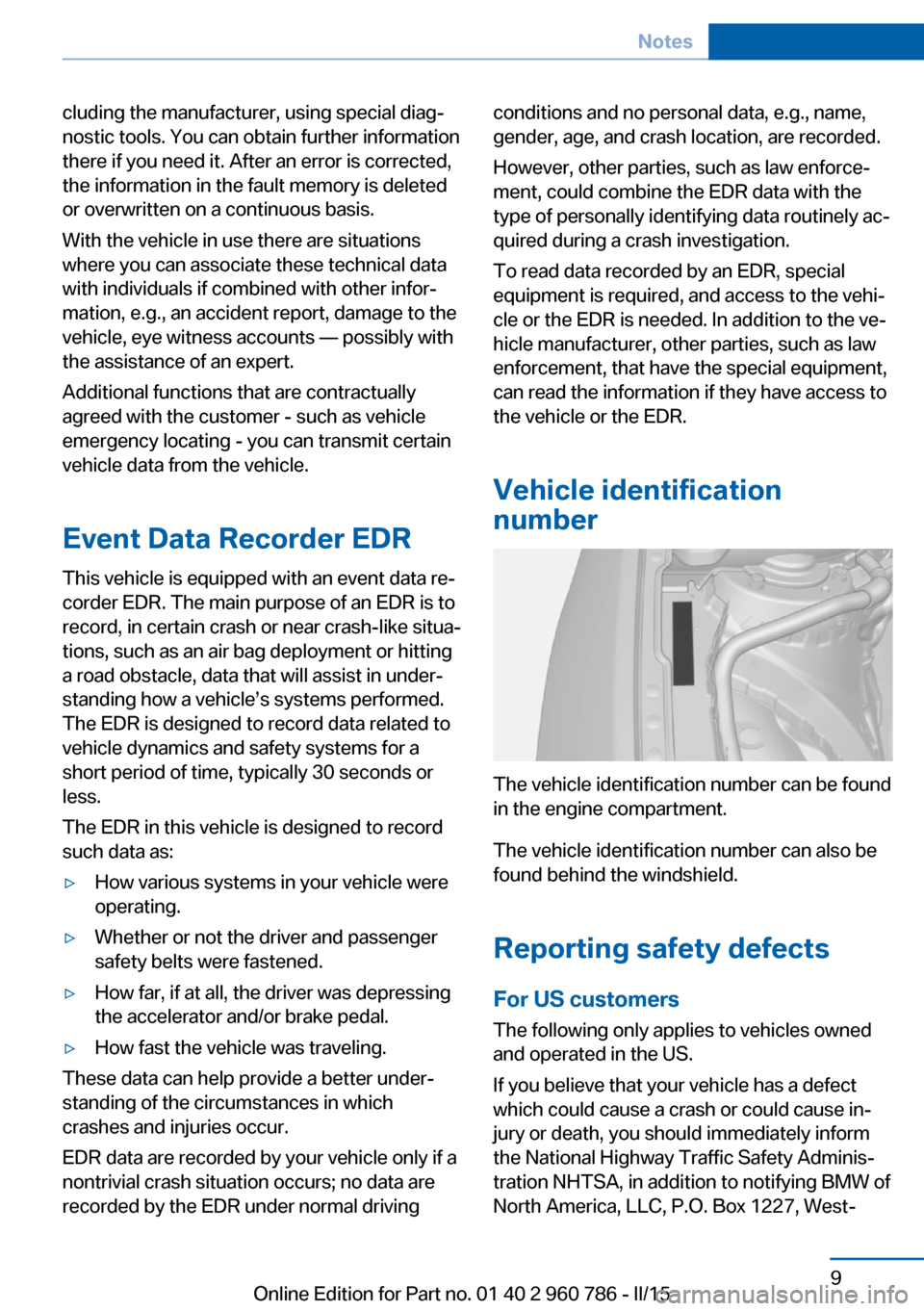
The vehicle identification number can be found
in the engine compartment.
The vehicle identification number can also be
found behind the windshield.
Reporting safety defects
For US customers The following only applies to vehicles owned
and operated in the US.
If you believe that your vehicle has a defect
which could cause a crash or could cause in‐
jury or death, you should immediately inform
the National Highway Traffic Safety Adminis‐
tration NHTSA, in addition to notifying BMW of
North America, LLC, P.O. Box 1227, West‐
Seite 9Notes9
Online Edition for Part no. 01 40 2 960 786 - II/15
Page 39 of 228
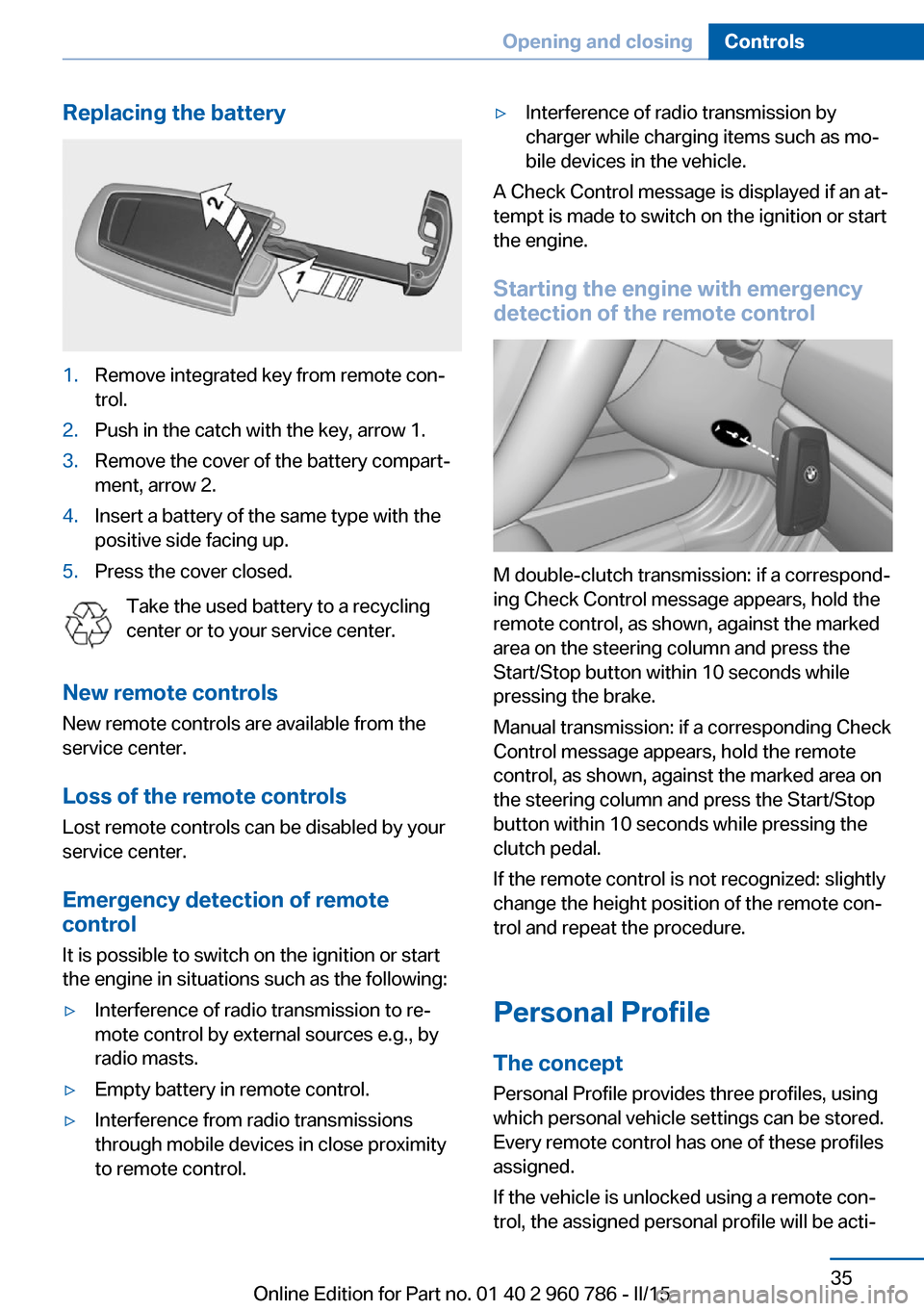
Replacing the battery1.Remove integrated key from remote con‐
trol.2.Push in the catch with the key, arrow 1.3.Remove the cover of the battery compart‐
ment, arrow 2.4.Insert a battery of the same type with the
positive side facing up.5.Press the cover closed.
Take the used battery to a recycling
center or to your service center.
New remote controls New remote controls are available from the
service center.
Loss of the remote controls Lost remote controls can be disabled by your
service center.
Emergency detection of remote
control
It is possible to switch on the ignition or start
the engine in situations such as the following:
▷Interference of radio transmission to re‐
mote control by external sources e.g., by
radio masts.▷Empty battery in remote control.▷Interference from radio transmissions
through mobile devices in close proximity
to remote control.▷Interference of radio transmission by
charger while charging items such as mo‐
bile devices in the vehicle.
A Check Control message is displayed if an at‐
tempt is made to switch on the ignition or start
the engine.
Starting the engine with emergency
detection of the remote control
M double-clutch transmission: if a correspond‐
ing Check Control message appears, hold the
remote control, as shown, against the marked
area on the steering column and press the
Start/Stop button within 10 seconds while
pressing the brake.
Manual transmission: if a corresponding Check
Control message appears, hold the remote
control, as shown, against the marked area on
the steering column and press the Start/Stop
button within 10 seconds while pressing the
clutch pedal.
If the remote control is not recognized: slightly
change the height position of the remote con‐
trol and repeat the procedure.
Personal Profile
The concept Personal Profile provides three profiles, using
which personal vehicle settings can be stored.
Every remote control has one of these profiles
assigned.
If the vehicle is unlocked using a remote con‐
trol, the assigned personal profile will be acti‐
Seite 35Opening and closingControls35
Online Edition for Part no. 01 40 2 960 786 - II/15
Page 118 of 228
Driving stability control systemsVehicle features and optionsThis chapter describes all standard, country-
specific and optional features offered with the
series. It also describes features that are not
necessarily available in your car, e. g., due to
the selected options or country versions. This
also applies to safety-related functions and
systems. The respectively applicable country
provisions must be observed when using the
respective features and systems.
Antilock Brake System ABS ABS prevents locking of the wheels during
braking.
The vehicle contains its steering power even
during full brake applications, thus increasing
active safety.
ABS is operational every time you start the en‐
gine.
Brake assistant When you apply the brakes rapidly, this system
automatically produces the greatest possible
braking force boost. It reduces the braking dis‐
tance to a minimum during emergency stop.
This system utilizes all of the benefits provided
by ABS.
Do not reduce the pressure on the brake pedal
for the duration of the emergency stop.
M Drive The conceptIndividual settings can be carried out in two
preassigned configurations for the vehicle.When the engine is started, an efficient driving
state is active by default. M Drive is deacti‐
vated.
At a glance
Configurations
The configurations are preassigned as follows:▷"M Drive 1": relaxed, comfortable driving.▷"M Drive 2": sporty, dynamic driving.
Setting options
SymbolMeaning Dynamic Stability Control DSC, re‐
fer to page 115, and M Dynamic
Mode MDM. Programs of M Engine Dynamics
Control, refer to page 74. Programs of the Adaptive M chas‐
sis, refer to page 117. Programs of Servotronic, refer to
page 118. Drivelogic, refer to page 72: shift
modes and Drivelogic driving pro‐
grams. Views of the Head-up Display, refer
to page 90.
Configuring M Drive
The preassigned configurations can be individ‐
ually adjusted.
On the Control Display:
1."Settings"2."M Drive 1" or "M Drive 2"Seite 114ControlsDriving stability control systems114
Online Edition for Part no. 01 40 2 960 786 - II/15
Page 198 of 228
that the foam rubber sealing ring is on the
centering pin.6.Release the catch at the top on the con‐
nector of the connecting line and remove
the connector from the bulb holder.
Replacing the bulbs
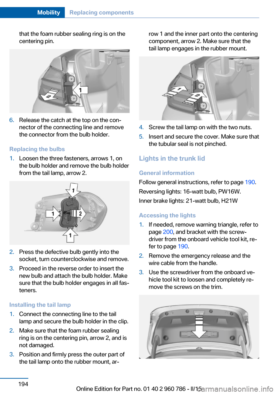
1.Loosen the three fasteners, arrows 1, on
the bulb holder and remove the bulb holder
from the tail lamp, arrow 2.2.Press the defective bulb gently into the
socket, turn counterclockwise and remove.3.Proceed in the reverse order to insert the
new bulb and attach the bulb holder. Make
sure that the bulb holder engages in all fas‐
teners.
Installing the tail lamp
1.Connect the connecting line to the tail
lamp and secure the bulb holder in the clip.2.Make sure that the foam rubber sealing
ring is on the centering pin, arrow 2, and is
not damaged.3.Position and firmly press the outer part of
the tail lamp onto the rubber mount, ar‐row 1 and the inner part onto the centering
component, arrow 2. Make sure that the
tail lamp engages in the rubber mount.4.Screw the tail lamp on with the two nuts.5.Insert and secure the cover. Make sure that
the tubular seal is not pinched.
Lights in the trunk lid
General information
Follow general instructions, refer to page 190.
Reversing lights: 16-watt bulb, PW16W.
Inner brake lights: 21-watt bulb, H21W
Accessing the lights
1.If needed, remove warning triangle, refer to
page 200, and bracket with the screw‐
driver from the onboard vehicle tool kit, re‐
fer to page 190.2.Remove the emergency release and the
wire cable from the handle.3.Use the screwdriver from the onboard ve‐
hicle tool kit to loosen and completely re‐
move the screws on the trim.Seite 194MobilityReplacing components194
Online Edition for Part no. 01 40 2 960 786 - II/15
Page 222 of 228
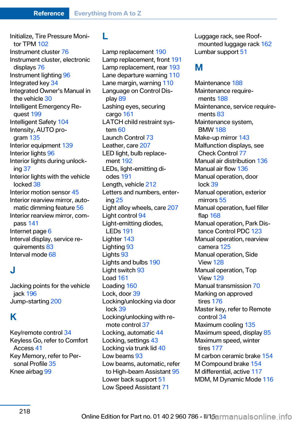
Initialize, Tire Pressure Moni‐tor TPM 102
Instrument cluster 76
Instrument cluster, electronic displays 76
Instrument lighting 96
Integrated key 34
Integrated Owner's Manual in the vehicle 30
Intelligent Emergency Re‐ quest 199
Intelligent Safety 104
Intensity, AUTO pro‐ gram 135
Interior equipment 139
Interior lights 96
Interior lights during unlock‐ ing 37
Interior lights with the vehicle locked 38
Interior motion sensor 45
Interior rearview mirror, auto‐ matic dimming feature 56
Interior rearview mirror, com‐ pass 141
Internet page 6
Interval display, service re‐ quirements 83
Interval mode 68
J Jacking points for the vehicle jack 196
Jump-starting 200
K
Key/remote control 34
Keyless Go, refer to Comfort Access 41
Key Memory, refer to Per‐ sonal Profile 35
Knee airbag 99 L
Lamp replacement 190
Lamp replacement, front 191
Lamp replacement, rear 193
Lane departure warning 110
Lane margin, warning 110
Language on Control Dis‐ play 89
Lashing eyes, securing cargo 161
LATCH child restraint sys‐ tem 60
Launch Control 73
Leather, care 207
LED light, bulb replace‐ ment 192
LEDs, light-emitting di‐ odes 191
Length, vehicle 212
Letters and numbers, enter‐ ing 25
Light alloy wheels, care 207
Light control 94
Light-emitting diodes, LEDs 191
Lighter 143
Lighting 93
Lights 93
Lights and bulbs 190
Light switch 93
Load 161
Loading 160
Lock, door 39
Locking/unlocking via door lock 39
Locking/unlocking with re‐ mote control 37
Locking, automatic 44
Locking, settings 43
Locking via trunk lid 40
Low beams 93
Low beams, automatic, refer to High-beam Assistant 95
Lower back support 51
Low Speed Assistant 71 Luggage rack, see Roof-
mounted luggage rack 162
Lumbar support 51
M
Maintenance 188
Maintenance require‐ ments 188
Maintenance, service require‐ ments 83
Maintenance system, BMW 188
Make-up mirror 143
Malfunction displays, see Check Control 77
Manual air distribution 136
Manual air flow 136
Manual operation, door lock 39
Manual operation, exterior mirrors 55
Manual operation, fuel filler flap 168
Manual operation, Park Dis‐ tance Control PDC 123
Manual operation, rearview camera 125
Manual operation, Side View 128
Manual operation, Top View 129
Manual transmission 70
Marking on approved tires 176
Master key, refer to Remote control 34
Maximum cooling 135
Maximum speed, display 85
Maximum speed, winter tires 177
M carbon ceramic brake 154
M Compound brake 154
M differential, active 117
MDM, M Dynamic Mode 116 Seite 218ReferenceEverything from A to Z218
Online Edition for Part no. 01 40 2 960 786 - II/15