second BMW M5 2000 E39 Central Body Electronics ZKE Manual
[x] Cancel search | Manufacturer: BMW, Model Year: 2000, Model line: M5, Model: BMW M5 2000 E39Pages: 80, PDF Size: 4.14 MB
Page 40 of 80

Principle of Operation
DWA Arming/Disarming
• The DWA is armed every time the vehicle is locked from the outside with the door lock
cylinder or FZV key.
• The DWA LED flashes as an acknowledgment along with the exterior lights and a
momentary chirp from the siren.
• The GM monitors all required input signals for closed status (door closed, luggage com-
partment closed, etc.) The inputs must be in a closed status for a minimum of 3 sec-
onds for the GM to include them as an activation component. If after 3 seconds any
input signal not in the closed status is excluded (this is acknowledged by the DWA LED)
preventing false alarm activations. The hood switch can be “lifted” to the service posi-
tion to test the alarm with the hood open.
• If the DWA is armed a second time within 10 seconds, the tilt sensor and interior pro-
tection sensor are excluded as alarm activation components. This function is useful if
the vehicle is transported on a train or flat bed truck to prevent false alarm activations.
• While armed, the trunk can be opened with out the alarm being triggered as follows:
- If opened with the trunk remote button via the FZV, the GM prevents the alarm from
activating. (This feature is customizable under the Car Memory function).
- If opened with the key at the trunk lock cylinder the trunk key position switch sig-
nals the GM and in the same manner prevents the alarm from activating.
In either case, when the trunk is returned to the closed position, it is no longer con-
sidered as an activation signal.
Panic Mode Operation: When the trunk button is pressed and held, the GM is signaled
to activate the siren for the Panic Mode. The panic mode is function with either an armed
or disarmed DWA system.
Emergency Disarming: Emergency disarming occurs automatically if a key is used to turn
the ignition switch on and the EWS accepts it. The EWS signals the GM to unlock the doors
and deactivate the DWA.
40
Central Body Electronics ZKE III
Page 41 of 80
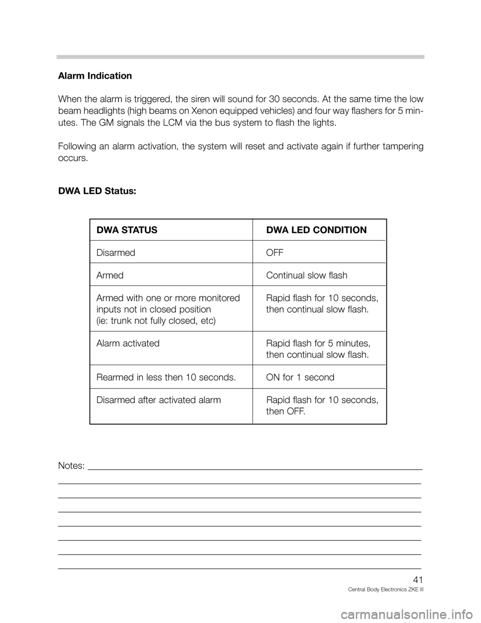
Alarm Indication
When the alarm is triggered, the siren will sound for 30 seconds. At the same time the low
beam headlights (high beams on Xenon equipped vehicles) and four way flashers for 5 min-
utes. The GM signals the LCM via the bus system to flash the lights.
Following an alarm activation, the system will reset and activate again if further tampering
occurs.
DWA LED Status:
Notes: _______________________________________________________________________
_____________________________________________________________________________
_____________________________________________________________________________
_____________________________________________________________________________
_____________________________________________________________________________
_____________________________________________________________________________
_____________________________________________________________________________
_____________________________________________________________________________
41
Central Body Electronics ZKE III
DWA STATUS DWA LED CONDITION
Disarmed OFF
Armed Continual slow flash
Armed with one or more monitored Rapid flash for 10 seconds,
inputs not in closed position then continual slow flash.
(ie: trunk not fully closed, etc)
Alarm activated Rapid flash for 5 minutes,
then continual slow flash.
Rearmed in less then 10 seconds. ON for 1 second
Disarmed after activated alarm Rapid flash for 10 seconds,
then OFF.
Page 42 of 80
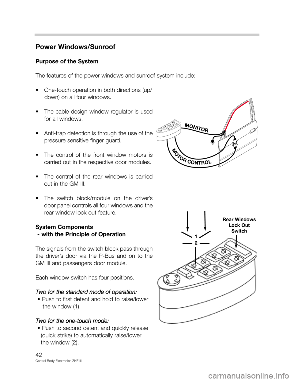
Power Windows/Sunroof
Purpose of the System
The features of the power windows and sunroof system include:
• One-touch operation in both directions (up/
down) on all four windows.
• The cable design window regulator is used
for all windows.
• Anti-trap detection is through the use of the
pressure sensitive finger guard.
• The control of the front window motors is
carried out in the respective door modules.
• The control of the rear windows is carried
out in the GM III.
• The switch block/module on the driver’s
door panel controls all four windows and the
rear window lock out feature.
System Components
- with the Principle of Operation
The signals from the switch block pass through
the driver’s door via the P-Bus and on to the
GM III and passengers door module.
Each window switch has four positions.
Two for the standard mode of operation:
• Push to first detent and hold to raise/lower
the window (1).
Two for the one-touch mode:
• Push to second detent and quickly release
(quick strike) to automatically raise/lower
the window (2).
42
Central Body Electronics ZKE III
1
2
Rear Windows
Lock Out
Switch
Page 43 of 80
All window operations signals are digital inputs to the door module and GM III.
• Comfort closing/opening of the windows from the driver’s lock cylinder. The remote key
provides opening only.
• When the ignition key is in accessory or “on” position press the switch to open or close
the windows. Window operation is possible with the ignition switched off until a front
door is opened or 16 minutes (maximum) has elapsed.
• Window load switching is through relays. The front window control relays are located in
the door modules, the rear window relays are in the GM III. The GM III monitors the cur-
rent draw for end limit position. The maximum run time for the window motors is limit-
ed to 6 seconds in the one-touch mode. This allows the motors to be switched off if the
end limit load sensing fails.
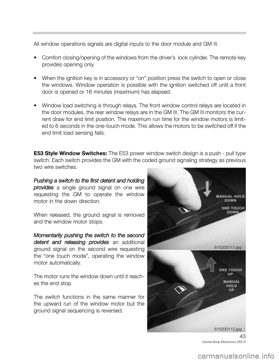
E53 Style Window Switches:The E53 power window switch design is a push - pull type
switch. Each switch provides the GM with the coded ground signaling strategy as previous
two wire switches.
Pushing a switch to the first detent and holding
provides
a single ground signal on one wire
requesting the GM to operate the window
motor in the down direction.
When released, the ground signal is removed
and the window motor stops.
Momentarily pushing the switch to the second
detent and releasing provides
an additional
ground signal on the second wire requesting
the “one touch mode”, operating the window
motor automatically.
The motor runs the window down until it reach-
es the end stop.
The switch functions in the same manner for
the upward run of the window motor but the
ground signal sequencing is reversed.
43
Central Body Electronics ZKE III
615200111.jpg
615200112.jpg
Page 46 of 80
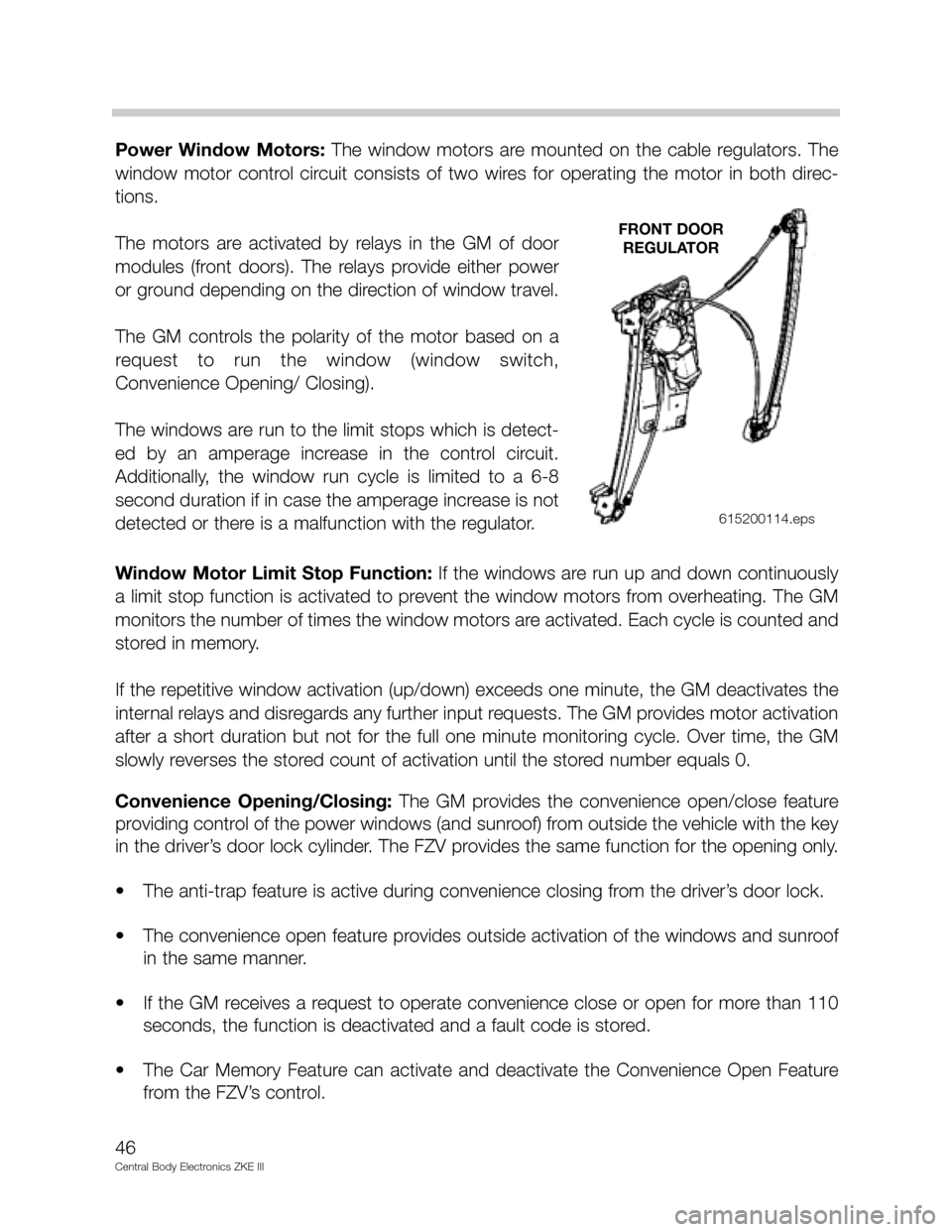
Power Window Motors: The window motors are mounted on the cable regulators. The
window motor control circuit consists of two wires for operating the motor in both direc-
tions.
The motors are activated by relays in the GM of door
modules (front doors). The relays provide either power
or ground depending on the direction of window travel.
The GM controls the polarity of the motor based on a
request to run the window (window switch,
Convenience Opening/ Closing).
The windows are run to the limit stops which is detect-
ed by an amperage increase in the control circuit.
Additionally, the window run cycle is limited to a 6-8
second duration if in case the amperage increase is not
detected or there is a malfunction with the regulator.
Window Motor Limit Stop Function: If the windows are run up and down continuously
a limit stop function is activated to prevent the window motors from overheating. The GM
monitors the number of times the window motors are activated. Each cycle is counted and
stored in memory.
If the repetitive window activation (up/down) exceeds one minute, the GM deactivates the
internal relays and disregards any further input requests. The GM provides motor activation
after a short duration but not for the full one minute monitoring cycle. Over time, the GM
slowly reverses the stored count of activation until the stored number equals 0.
Convenience Opening/Closing: The GM provides the convenience open/close feature
providing control of the power windows (and sunroof) from outside the vehicle with the key
in the driver’s door lock cylinder. The FZV provides the same function for the opening only.
• The anti-trap feature is active during convenience closing from the driver’s door lock.
• The convenience open feature provides outside activation of the windows and sunroof
in the same manner.
• If the GM receives a request to operate convenience close or open for more than 110
seconds, the function is deactivated and a fault code is stored.
• The Car Memory Feature can activate and deactivate the Convenience Open Feature
from the FZV’s control.
46
Central Body Electronics ZKE III
FRONT DOOR
REGULATOR
615200114.eps
Page 47 of 80
Sunroof
Purpose of the System
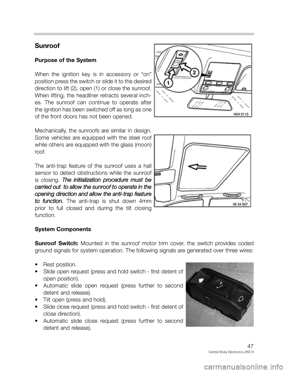
When the ignition key is in accessory or “on”
position press the switch or slide it to the desired
direction to lift (2), open (1) or close the sunroof.
When lifting, the headliner retracts several inch-
es. The sunroof can continue to operate after
the ignition has been switched off as long as one
of the front doors has not been opened.
Mechanically, the sunroofs are similar in design.
Some vehicles are equipped with the steel roof
while others are equipped with the glass (moon)
roof.
The anti-trap feature of the sunroof uses a hall
sensor to detect obstructions while the sunroof
is closing. The initialization procedure must be
carried out to allow the sunroof to operate in the
opening direction and allow the anti-trap feature
to function.
The anti-trap is shut down 4mm
prior to full closed and during the tilt closing
function.
System Components
Sunroof Switch:Mounted in the sunroof motor trim cover, the switch provides coded
ground signals for system operation. The following signals are generated over three wires:
• Rest position.
• Slide open request (press and hold switch - first detent of
open position).
• Automatic slide open request (press further to second
detent and release).
• Tilt open (press and hold).
• Slide close request (press and hold switch - first detent of
close direction).
• Automatic slide close request (press further to second
detent and release).
47
Central Body Electronics ZKE III
Page 51 of 80
Interior Lighting
Purpose of the System
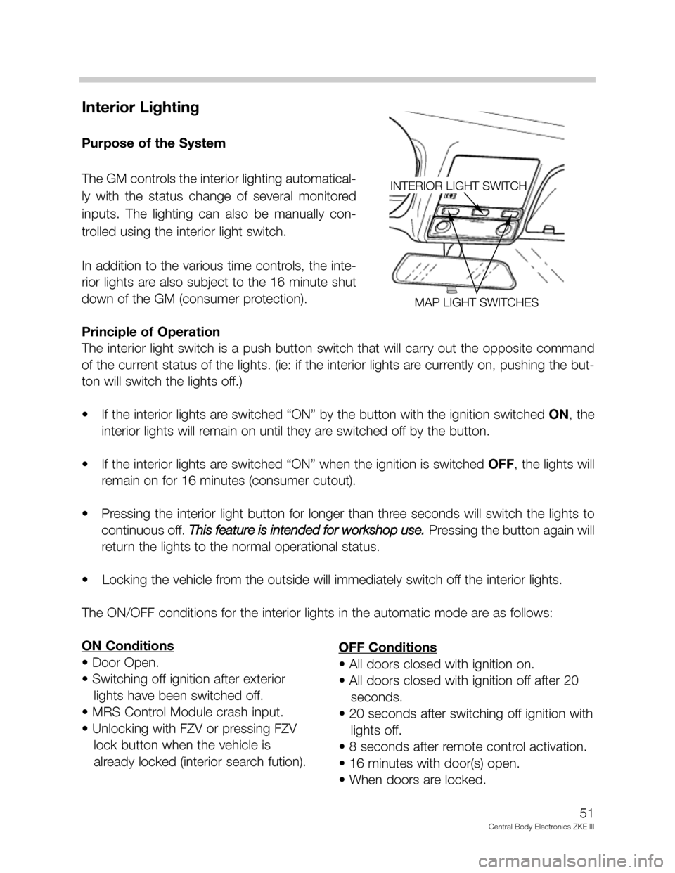
The GM controls the interior lighting automatical-
ly with the status change of several monitored
inputs. The lighting can also be manually con-
trolled using the interior light switch.
In addition to the various time controls, the inte-
rior lights are also subject to the 16 minute shut
down of the GM (consumer protection).
Principle of Operation
The interior light switch is a push button switch that will carry out the opposite command
of the current status of the lights. (ie: if the interior lights are currently on, pushing the but-
ton will switch the lights off.)
• If the interior lights are switched “ON” by the button with the ignition switched ON, the
interior lights will remain on until they are switched off by the button.
• If the interior lights are switched “ON” when the ignition is switched OFF, the lights will
remain on for 16 minutes (consumer cutout).
• Pressing the interior light button for longer than three seconds will switch the lights to
continuous off. This feature is intended for workshop use.
Pressing the button again will
return the lights to the normal operational status.
• Locking the vehicle from the outside will immediately switch off the interior lights.
The ON/OFF conditions for the interior lights in the automatic mode are as follows:
ON Conditions
• Door Open.
• Switching off ignition after exterior
lights have been switched off.
• MRS Control Module crash input.
• Unlocking with FZV or pressing FZV
lock button when the vehicle is
already locked (interior search fution).
51
Central Body Electronics ZKE III
OFF Conditions
• All doors closed with ignition on.
• All doors closed with ignition off after 20
seconds.
• 20 seconds after switching off ignition with
lights off.
• 8 seconds after remote control activation.
• 16 minutes with door(s) open.
• When doors are locked.
Page 53 of 80
System Components
Door Contacts: As mentioned in the Central Locking Section, the existing door contacts
opened/closed are also an input for the interior lighting function. The E53 uses the Hall
effect sensors for the purpose of monitoring door open/closed status (located directly
behind the rotary latch plate encased in the actuator). The sensor is activated by the rotary
latch plate's position.
• Door closed, the rotary latch plate is in the latched position. Current flow through the
hall sensor is < 5 mA.
• Door open, the rotary latch plate is in the open position. Current flow through the hall
sensor is > 12 mA.
A change in current flow informs the General module when a door is opened or closed.
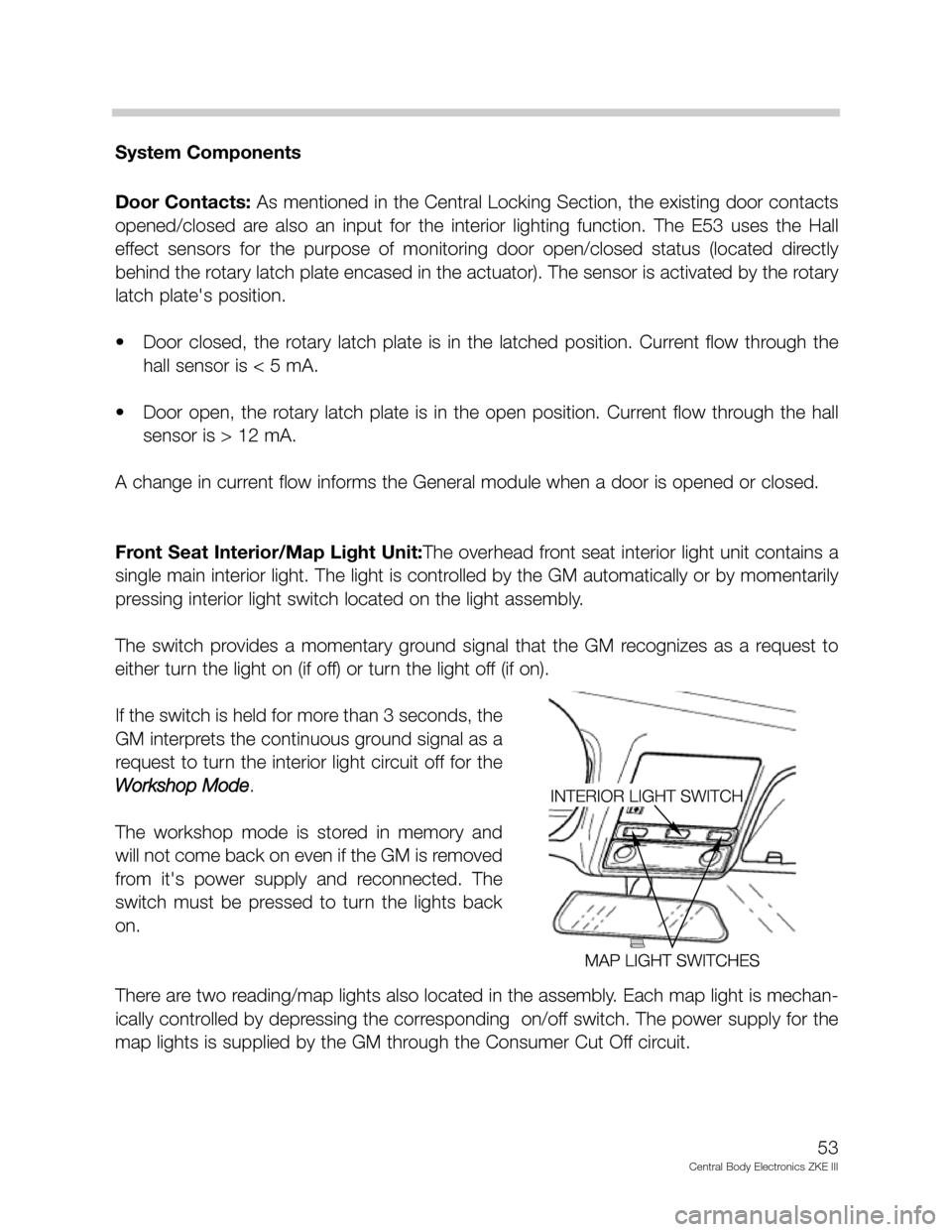
Front Seat Interior/Map Light Unit:The overhead front seat interior light unit contains a
single main interior light. The light is controlled by the GM automatically or by momentarily
pressing interior light switch located on the light assembly.
The switch provides a momentary ground signal that the GM recognizes as a request to
either turn the light on (if off) or turn the light off (if on).
If the switch is held for more than 3 seconds, the
GM interprets the continuous ground signal as a
request to turn the interior light circuit off for the
Workshop Mode
.
The workshop mode is stored in memory and
will not come back on even if the GM is removed
from it's power supply and reconnected. The
switch must be pressed to turn the lights back
on.
There are two reading/map lights also located in the assembly. Each map light is mechan-
ically controlled by depressing the corresponding on/off switch. The power supply for the
map lights is supplied by the GM through the Consumer Cut Off circuit.
53
Central Body Electronics ZKE III
Page 57 of 80
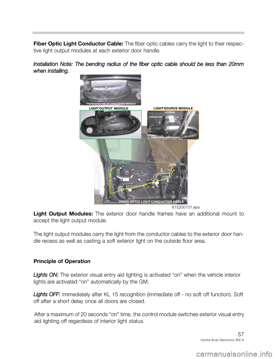
Fiber Optic Light Conductor Cable:The fiber optic cables carry the light to their respec-
tive light output modules at each exterior door handle.
Installation Note:The bending radius of the fiber optic cable should be less than 20mm
when installing.
Light Output Modules: The exterior door handle frames have an additional mount to
accept the light output module.
The light output modules carry the light from the conductor cables to the exterior door han-
dle recess as well as casting a soft exterior light on the outside floor area.
Principle of Operation
Lights ON:
The exterior visual entry aid lighting is activated “on” when the vehicle interior
lights are activated “on” automatically by the GM.
Lights OFF:
Immediately after KL 15 recognition (immediate off - no soft off function). Soft
off after a short delay once all doors are closed.
After a maximum of 20 seconds “on” time, the control module switches exterior visual entry
aid lighting off regardless of interior light status.
57
Central Body Electronics ZKE III
615200131.eps
Page 59 of 80
59
Central Body Electronics ZKE III
System Components
- with Principle of Operation
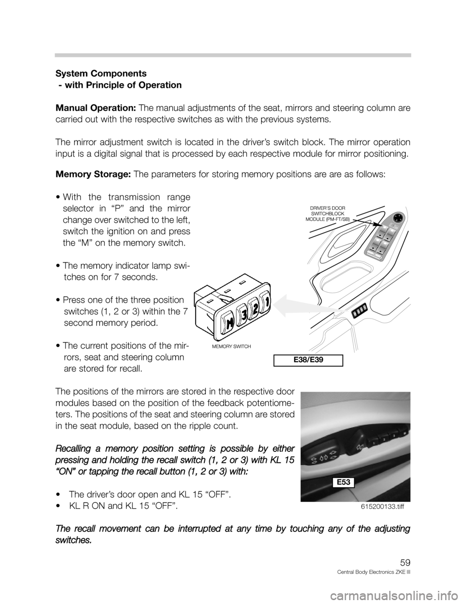
Manual Operation:The manual adjustments of the seat, mirrors and steering column are
carried out with the respective switches as with the previous systems.
The mirror adjustment switch is located in the driver’s switch block. The mirror operation
input is a digital signal that is processed by each respective module for mirror positioning.
Memory Storage: The parameters for storing memory positions are are as follows:
• With the transmission range
selector in “P” and the mirror
change over switched to the left,
switch the ignition on and press
the “M” on the memory switch.
• The memory indicator lamp swi-
tches on for 7 seconds.
• Press one of the three position
switches (1, 2 or 3) within the 7
second memory period.
• The current positions of the mir-
rors, seat and steering column
are stored for recall.
The positions of the mirrors are stored in the respective door
modules based on the position of the feedback potentiome-
ters. The positions of the seat and steering column are stored
in the seat module, based on the ripple count.
Recalling a memory position setting is possible by either
pressing and holding the recall switch (1, 2 or 3) with KL 15
“ON” or tapping the recall button (1, 2 or 3) with:
• The driver’s door open and KL 15 “OFF”.
• KL R ON and KL 15 “OFF”.
The recall movement can be interrupted at any time by touching any of the adjusting
switches.
E38/E39
E53
615200133.tiff