reset BMW M5 2013 F10 Owner's Manual
[x] Cancel search | Manufacturer: BMW, Model Year: 2013, Model line: M5, Model: BMW M5 2013 F10Pages: 230, PDF Size: 6.34 MB
Page 36 of 230
Profile management
Opening the profiles A different profile can be called up than the
one associated with the remote control cur‐
rently in use.1."Settings"2."Profiles"3.Select a profile.
Called up profile is assigned to the remote
control being used at the time.
Renaming profiles
1."Settings"2."Profiles"
The current profile is selected.3.Open "Options".4."Rename current profile"
Resetting profiles The settings of the active profile are reset to
their default values.
1."Settings"2."Profiles"
The current profile is selected.3.Open "Options".4."Reset current profile"
Importing profiles
Existing settings and contacts are overwritten
with the imported profile.
1."Settings"2."Profiles"3."Import profile"4.BMW Online: "BMW Online"
USB interface, refer to page 146: "USB
device"Exporting profiles
Most settings of the active profile and the
saved contacts can be exported.
This can be helpful for securing and retrieving
personal settings, before delivering the vehicle
to a workshop for example.1."Settings"2."Profiles"3."Export profile"4.BMW Online: "BMW Online"
USB interface, refer to page 146: "USB
device"
Using the guest profile
The guest profile can be used to make individ‐
ual settings without affecting the three Per‐
sonal Profiles.
This can be useful for drivers who are using
the vehicle temporarily and do not have their
own profile.
1."Settings"2."Profiles"
The current profile is selected.3.Open "Guest".4.Create the settings.
Note: the guest profile cannot be renamed.
Display profile list during start
The profile list can be displayed during each
start for selecting the desired profile.
1."Settings"2."Profiles"3.Open "Options".4."Display user list at startup"
Personal Profile settings
The following functions and settings can be
stored in a profile.
▷Collision warning: warning time.Seite 32ControlsOpening and closing32
Online Edition for Part no. 01 40 2 909 953 - VI/13
Page 62 of 230
Activating/deactivating M Drive
Activating Press the corresponding button on the steer‐
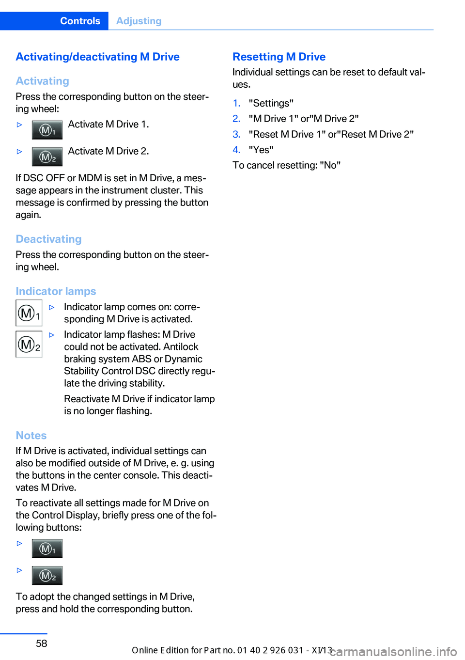
ing wheel:▷Activate M Drive 1.▷Activate M Drive 2.
If DSC OFF or MDM is set in M Drive, a mes‐
sage appears in the instrument cluster. This
message is confirmed by pressing the button
again.
Deactivating Press the corresponding button on the steer‐
ing wheel.
Indicator lamps
▷Indicator lamp comes on: corre‐
sponding M Drive is activated.▷Indicator lamp flashes: M Drive
could not be activated. Antilock
braking system ABS or Dynamic
Stability Control DSC directly regu‐
late the driving stability.
Reactivate M Drive if indicator lamp
is no longer flashing.
Notes
If M Drive is activated, individual settings can also be modified outside of M Drive, e. g. using
the buttons in the center console. This deacti‐
vates M Drive.
To reactivate all settings made for M Drive on
the Control Display, briefly press one of the fol‐
lowing buttons:
▷▷
To adopt the changed settings in M Drive,
press and hold the corresponding button.
Resetting M Drive
Individual settings can be reset to default val‐
ues.1."Settings"2."M Drive 1" or"M Drive 2"3."Reset M Drive 1" or"Reset M Drive 2"4."Yes"
To cancel resetting: "No"
Seite 58ControlsAdjusting58
Online Edition for Part no. 01 40 2 909 953 - VI/13
Page 82 of 230
DisplaysVehicle equipmentAll standard, country-specific and optional
equipment that is offered in the model series is
described in this chapter. Therefore, equip‐ment is also described that is not available in a
vehicle, e. g., because of the selected optional
equipment or country variant. This also applies
for safety-related functions and systems.
Instrument cluster
Overview, instrument cluster
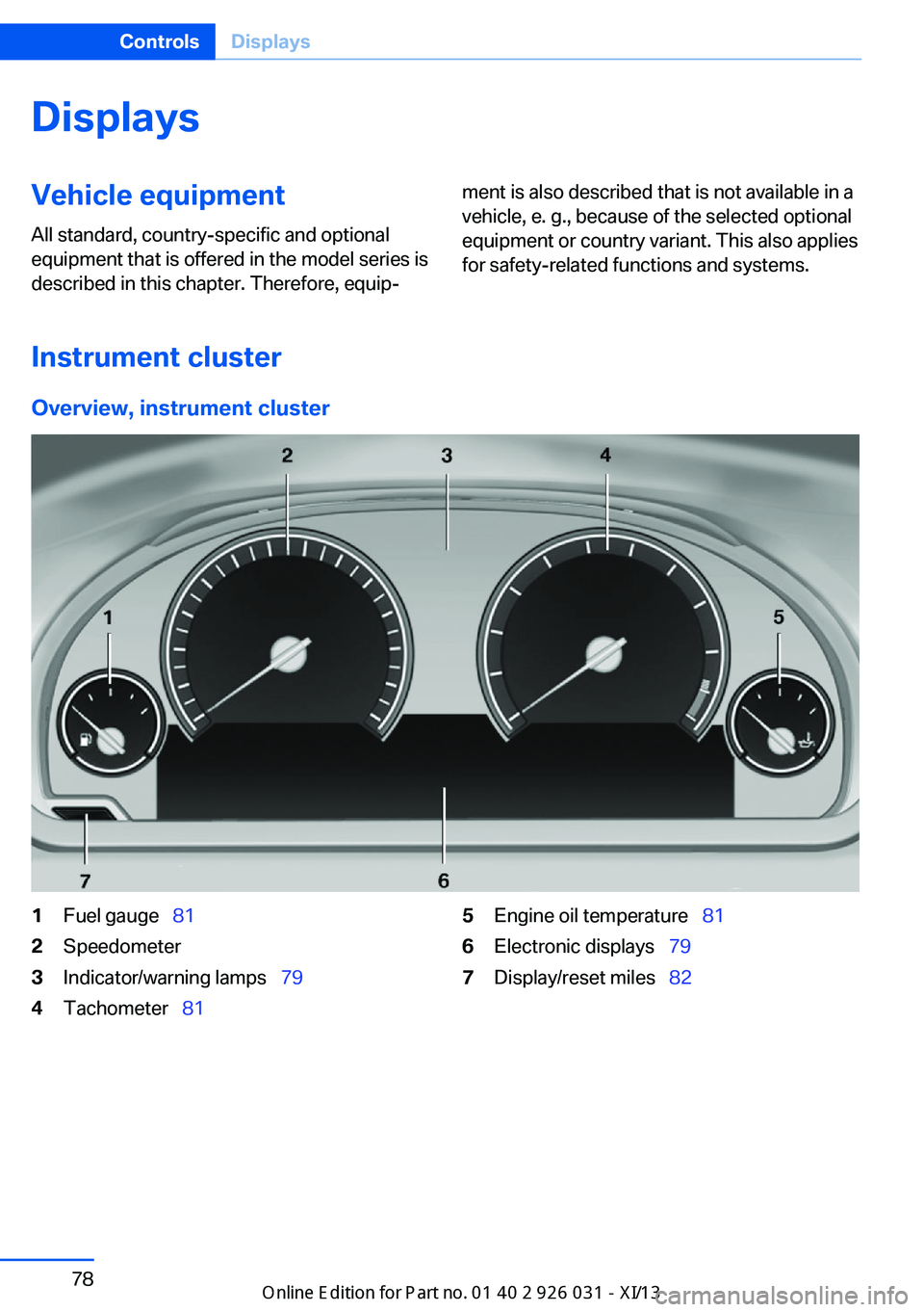
1Fuel gauge 812Speedometer3Indicator/warning lamps 794Tachometer 815Engine oil temperature 816Electronic displays 797Display/reset miles 82Seite 78ControlsDisplays78
Online Edition for Part no. 01 40 2 909 953 - VI/13
Page 86 of 230
▷Hot engine: the pointer is at the high tem‐
perature end. A Check Control message is
also displayed.
Coolant temperature
If the coolant along with the engine becomes
too hot, a Check Control message is displayed.
Check the coolant level, refer to page 189.
Odometer and trip odometer
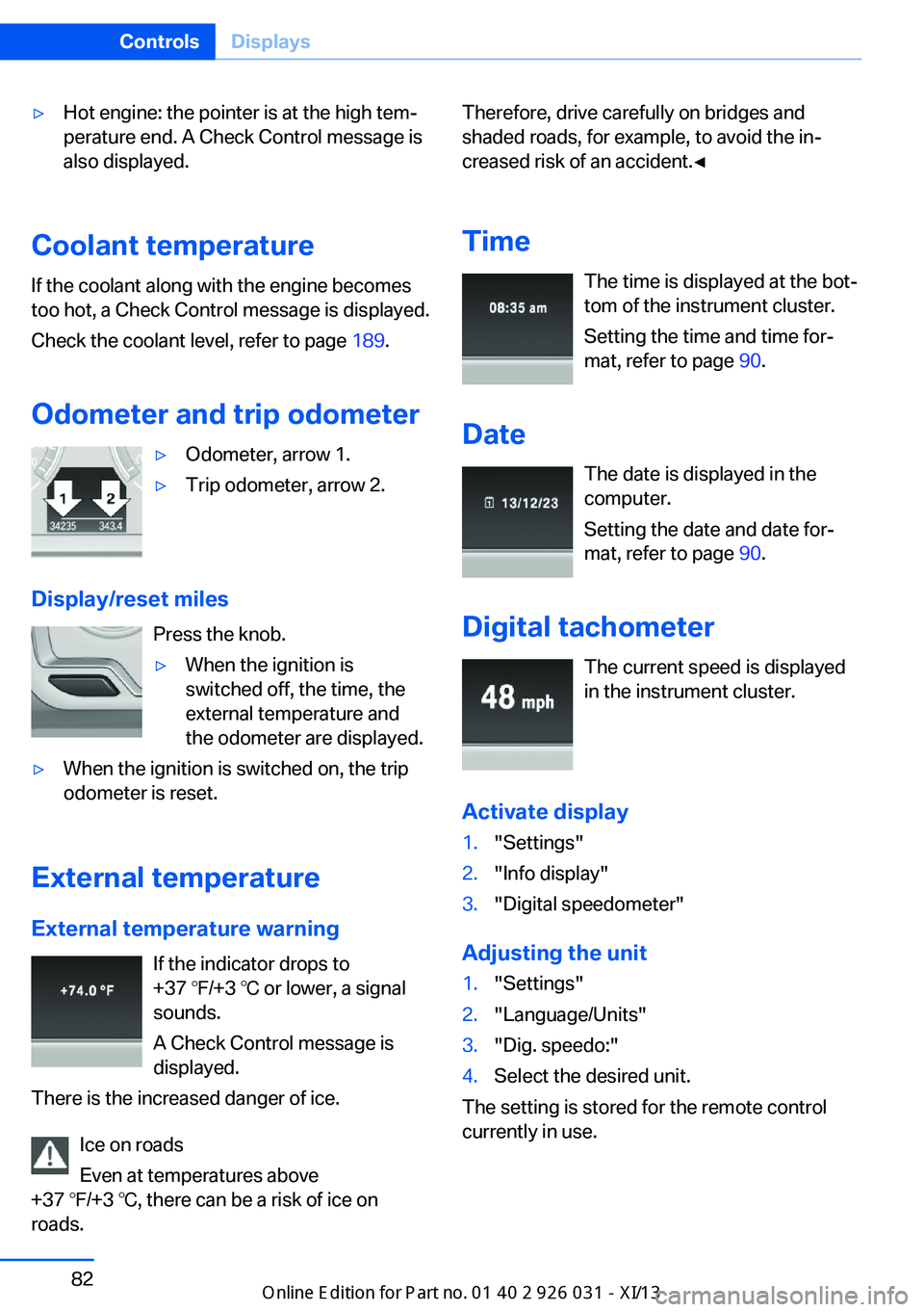
▷Odometer, arrow 1.▷Trip odometer, arrow 2.
Display/reset miles Press the knob.
▷When the ignition is
switched off, the time, the
external temperature and
the odometer are displayed.▷When the ignition is switched on, the trip
odometer is reset.
External temperature
External temperature warning If the indicator drops to
+37 ℉/+3 ℃ or lower, a signal
sounds.
A Check Control message is displayed.
There is the increased danger of ice.
Ice on roads
Even at temperatures above
+37 ℉/+3 ℃, there can be a risk of ice on
roads.
Therefore, drive carefully on bridges and
shaded roads, for example, to avoid the in‐
creased risk of an accident.◀
Time The time is displayed at the bot‐
tom of the instrument cluster.
Setting the time and time for‐
mat, refer to page 90.
Date The date is displayed in the
computer.
Setting the date and date for‐
mat, refer to page 90.
Digital tachometer The current speed is displayed
in the instrument cluster.
Activate display1."Settings"2."Info display"3."Digital speedometer"
Adjusting the unit
1."Settings"2."Language/Units"3."Dig. speedo:"4.Select the desired unit.
The setting is stored for the remote control
currently in use.
Seite 82ControlsDisplays82
Online Edition for Part no. 01 40 2 909 953 - VI/13
Page 88 of 230
EfficientDynamics displayInformation on fuel consumption and technol‐
ogy can be displayed during driving.1."Vehicle Info"2."EfficientDynamics"
Displaying fuel consumption history
The average fuel consumption can be dis‐
played within an adjustable time frame.
"Consumption history"
Adjusting fuel consumption history time frame
Select the symbol.
Resetting fuel consumption history
1.Open "Options".2."Reset consumption history"
Displaying EfficientDynamics info
The current efficiency can be displayed.
"EfficientDynamics info"
The following systems are displayed:
▷Automatic engine Start/Stop function.▷Energy recovery.▷Climate control output.
Driving dynamics systems
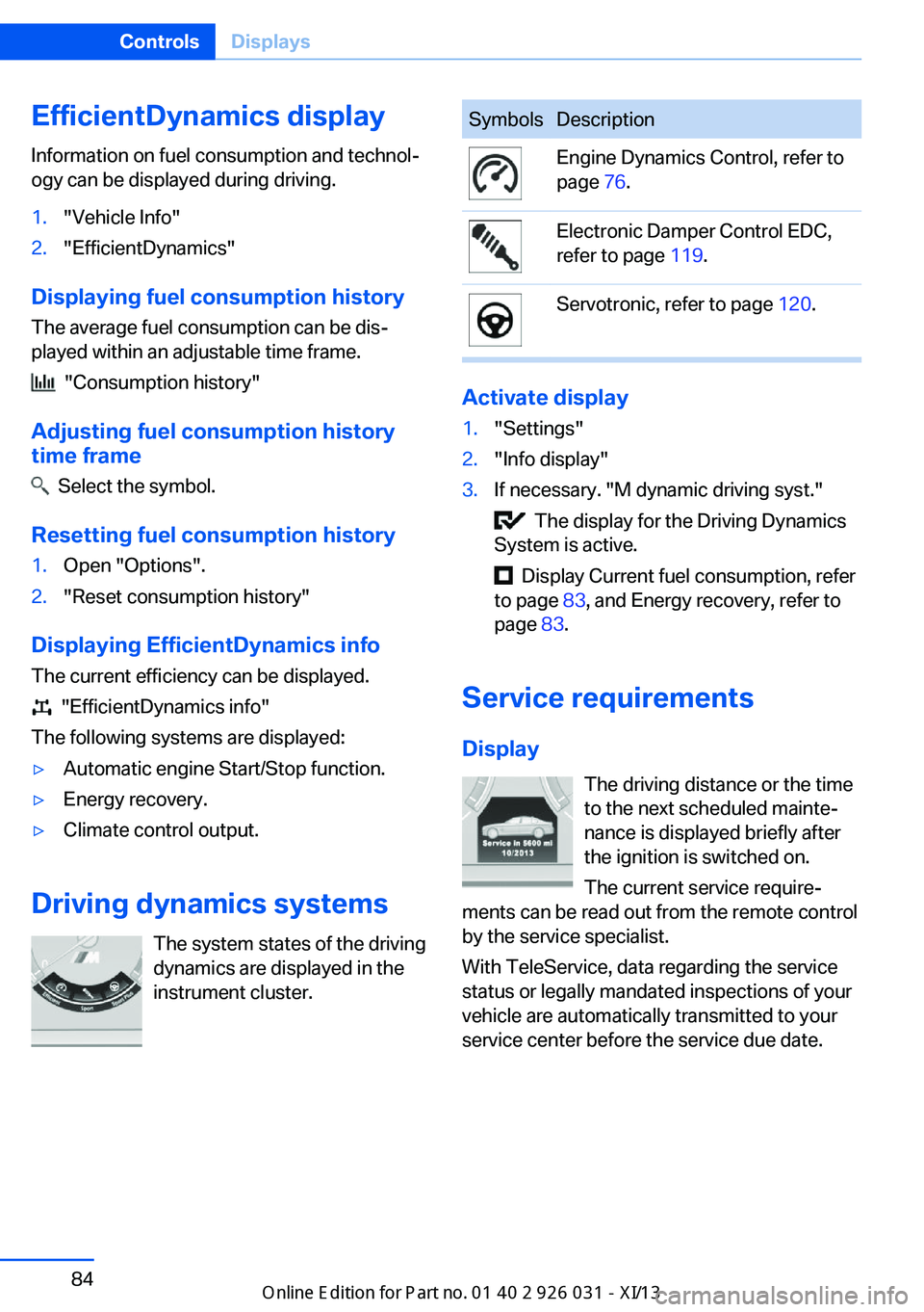
The system states of the driving
dynamics are displayed in the
instrument cluster.
SymbolsDescriptionEngine Dynamics Control, refer to
page 76.Electronic Damper Control EDC,
refer to page 119.Servotronic, refer to page 120.
Activate display
1."Settings"2."Info display"3.If necessary. "M dynamic driving syst."
The display for the Driving Dynamics
System is active.
Display Current fuel consumption, refer
to page 83, and Energy recovery, refer to
page 83.
Service requirements
Display The driving distance or the time
to the next scheduled mainte‐
nance is displayed briefly after
the ignition is switched on.
The current service require‐
ments can be read out from the remote control
by the service specialist.
With TeleService, data regarding the service
status or legally mandated inspections of your
vehicle are automatically transmitted to your
service center before the service due date.
Seite 84ControlsDisplays84
Online Edition for Part no. 01 40 2 909 953 - VI/13
Page 93 of 230
When destination guidance is activated in
the navigation system.
When the arrow view in the Head-up Dis‐
play is inactive.
Adjusting the info display
You can select what information from the on‐
board computer is to be displayed on the info
display of the instrument cluster.
1."Settings"2."Info display"3.Select the desired displays.
Information in detail
Range
Displays the estimated cruising range available
with the remaining fuel.
It is calculated based on your driving style over
the last 20 miles/30 km.
Average fuel consumption
The average fuel consumption is calculated for
the period during which the engine is running.
The average fuel consumption is calculated for
the distance traveled since the last reset by the
onboard computer.
Average speed
Periods in which the vehicle is parked with the
engine manually stopped do not enter into the
calculation of the average speed.
Resetting average values
Press and hold the computer button on the turn signal lever.
Distance to destination
The distance remaining to the destination is
displayed if a destination is entered in the navi‐
gation system before the trip is started.
The distance to the destination is adopted au‐
tomatically.
Time of arrival
The estimated time of arrival is
displayed if a destination is en‐
tered in the navigation system
before the trip is started.
The time must be correctly set.
Speed limit detection
Description of the speed limit detection, refer
to page 86, function.
Speed limit
Display of a speed limit which, when reached,
should cause a warning to be issued.
The warning is repeated if the vehicle speed
drops below the set speed limit once by at least 3 mph/5 km/h.
Displaying, setting or changing the
limit1."Settings"2."Speed"3."Warning at:"4.Turn the controller until the desired limit is
displayed.5.Press the controller.
The speed limit is stored.
Activating/deactivating the limit
1."Settings"2."Speed"3."Warning"4.Press the controller.
Setting your current speed as the limit
1."Settings"2."Speed"3."Select current speed"4.Press the controller.Seite 89DisplaysControls89
Online Edition for Part no. 01 40 2 909 953 - VI/13
Page 94 of 230
The current vehicle speed is stored as the
limit.
Trip computer
The vehicle features two types of computer.
▷"Onboard info": the values can be reset as
often as necessary.▷"Trip computer": the values provide an
overview of the current trip.
Resetting the trip computer
1."Vehicle Info"2."Trip computer"3."Reset": all values are reset.
"Automatically reset": all values are reset
approx. 4 hours after the vehicle comes to
a standstill.
Display on the Control Display
Display the onboard computer or trip computer
on the Control Display.
1."Vehicle Info"2."Onboard info" or "Trip computer"
Resetting the fuel consumption or
speed
1."Vehicle Info"2."Onboard info"3."Consumpt." or "Speed"4."Yes"
Settings on the Control
Display
Time
Setting the time zone
1."Settings"2."Time/Date"3."Time zone"4.Select the desired time zone.
The time zone is stored.
Setting the time
1."Settings"2."Time/Date"3."Time:"4.Turn the controller until the desired hours
are displayed.5.Press the controller.6.Turn the controller until the desired mi‐
nutes are displayed.7.Press the controller.
The time is stored.
Setting the time format
1."Settings"2."Time/Date"3."Format:"4.Select the desired format.
The time format is stored.
Date
Setting the date
1."Settings"2."Time/Date"3."Date:"4.Turn the controller until the desired day is
displayed.5.Press the controller.6.Make the necessary settings for the month
and year.
The date is stored.
Setting the date format
1."Settings"2."Time/Date"Seite 90ControlsDisplays90
Online Edition for Part no. 01 40 2 909 953 - VI/13
Page 104 of 230
Detected child seatsThe system generally detects children seated
in a child seat, especially in the child seats that
were required by NHTSA when the vehicle was
manufactured. After installing a child seat,
make sure that the indicator lamp for the front
passenger airbags lights up. This indicates that the child seat has been detected and the
front passenger airbags are not activated.
Strength of the driver's and front
passenger airbag
The strength with which the driver's and front
passenger airbags are triggered depends on
the position of the driver's and front passenger
seats.
To maintain the accuracy of this function over
the long-term, calibrate the front seats when a
corresponding message appears on the Con‐
trol Display.
Calibrating the front seats A corresponding message appears on the
Control Display.1.Move the respective seat forward all the
way.2.Move the respective seat forward again. It
moves forward briefly.3.Readjust the seat to the desired position.
The calibration procedure is completed when
the message on the Control Display disap‐
pears.
If the message continues to be displayed, re‐
peat the calibration.
If the message does not disappear after a re‐
peat calibration, have the system checked as
soon as possible.
Unobstructed area of movement
Ensure that the area of movement of the
seats is unobstructed to avoid personal injury
or damage to objects.◀
Tire Pressure Monitor TPM
The concept The system monitors tire pressure in the four
mounted tires. The system warns you if there
is a significant loss of pressure in one or more
tires. For this purpose, sensors in the tire
valves measure the tire pressure and tire tem‐
perature.
Hints Tire damage due to external factors
Sudden tire damage caused by external
influences cannot be indicated in advance.◀
Pay attention to the other information and indi‐
cations under Tire inflation pressure, refer to
page 175, as well when using the system.
Functional requirements
The system must have been reset with the
correct tire inflation pressure; otherwise, relia‐
ble signaling of tire pressure loss is not en‐
sured.
Reset the system again after each correction
of the tire inflation pressure and after every tire
or wheel change.
Always use wheels with TPM electronics to
ensure that the system will operate properly.
Status display
The current status of the Tire Pressure Moni‐
tor TPM can be displayed on the Control Dis‐
play, e.g., whether or not the TPM is active.1."Vehicle Info"2."Vehicle status"3. "Tire Pressure Monitor"
The status is displayed.
Status display The tire and system status is indicated by the
color of the wheels and a text message on the
Control Display.
Seite 100ControlsSafety100
Online Edition for Part no. 01 40 2 909 953 - VI/13
Page 105 of 230
All wheels green
System is active and will issue a warning rela‐
tive to the tire inflation pressures stored during
the last reset.
One wheel is yellow
A flat tire or major drop in inflation pressure in
the indicated tire.
All wheels are yellow A flat tire or major drop in inflation pressure in
several tires.
Wheels, gray
The system cannot detect a flat tire. Reasons
for this may be:▷The system is being reset.▷Malfunction.
Additional information
The status display additionally shows the cur‐
rent tire inflation pressures and tire tempera‐
tures. The values shown are current measure‐
ment values and may vary depending on
driving style or weather conditions.
Carry out reset Reset the system after each correction of the
tire inflation pressure and after every tire or
wheel change.
1."Vehicle Info"2."Vehicle status"3. "Perform reset"4.Start the engine - do not drive away.5.Carry out the reset with "Perform reset".6.Drive away.
The tires are shown in gray and the status is
displayed.
After driving faster than 19 mph/30 km/h for a
short period, the tire inflation pressures set are
accepted as reference values. The reset is
completed automatically during driving.
After a successfully completed Reset, the
wheels on the Control Display are shown in
green and "Tire Pressure Monitor (TPM)
active" is displayed.
The trip can be interrupted at any time. If you
drive away again, the reset resumes automati‐
cally.
Low tire pressure message The yellow warning lamp lights up. A
Check Control message is displayed.▷There is a flat tire or a major loss in
tire inflation pressure.▷No reset was performed for the system.
The system therefore issues a warning
based on the tire pressures before the last
reset.1.Reduce your speed and stop cautiously.
Avoid sudden braking and steering maneu‐
vers.2.Identify the damaged wheel. Do so by
checking the tire inflation pressure using
the Mobility System. Correcting the tire in‐
flation pressure, refer to page 182.3.Repair flat tire with the Mobility System, re‐
fer to page 180, or replace the damaged
wheel.
Required inflation pressure check
message
A Check Control message is displayed.
Check the tire inflation pressure and carry out
a reset of the system.
In some cases, a wheel was changed without
having carried out a reset.
System limits
The system does not function properly if a re‐
set has not been carried out, e.g., a flat tire is
reported even though the tire inflation pres‐
sures are correct.
Seite 101SafetyControls101
Online Edition for Part no. 01 40 2 909 953 - VI/13
Page 106 of 230
The tire pressure depends on the temperature
of the tire. If the tire temperature rises, e.g.,
due to driving or because of the heat of the
Sun, the tire inflation pressure increases also.
The tire pressure is reduced when the tire
temperature falls again. This behavior may
cause a warning to be issued if temperatures
fall very sharply.
Malfunction The yellow warning lamp flashes and
then lights up continuously. A Check
Control message is displayed. No flat
tire or loss of tire pressure can be detected.
Display in the following situations:▷A wheel without TPM electronics is fitted:
have the service center check it if neces‐
sary.▷Malfunction: have the system checked by
your service center.▷TPM was unable to complete the reset.
Reset the system again.▷Disturbance by systems or devices with
the same radio frequency: after leaving the
area of the disturbance, the system auto‐
matically becomes active again.
Declaration according to NHTSA/
FMVSS 138 Tire Pressure Monitoring
System
Each tire, including the spare (if provided)
should be checked monthly when cold and in‐
flated to the inflation pressure recommended
by the vehicle manufacturer on the vehicle
placard or tire inflation pressure label. (If your
vehicle has tires of a different size than the size
indicated on the vehicle placard or tire inflation
pressure label, you should determine the
proper tire inflation pressure for those tires.)
As an added safety feature, your vehicle has
been equipped with a tire pressure monitoring
system (TPMS) that illuminates a low tire pres‐
sure telltale when one or more of your tires is
significantly under-inflated. Accordingly, when
the low tire pressure telltale illuminates, you
should stop and check your tires as soon as
possible, and inflate them to the proper pres‐
sure. Driving on a significantly under-inflated
tire causes the tire to overheat and can lead to
tire failure. Under-inflation also reduces fuel ef‐
ficiency and tire tread life, and may affect the
vehicle's handling and stopping ability. Please
note that the TPMS is not a substitute for
proper tire maintenance, and it is the driver's
responsibility to maintain correct tire pressure,
even if under-inflation has not reached the
level to trigger illumination of the TPMS low
tire pressure telltale. Your vehicle has also
been equipped with a TPMS malfunction indi‐
cator to indicate when the system is not oper‐
ating properly. The TPMS malfunction indica‐
tor is combined with the low tire pressure
telltale. When the system detects a malfunc‐
tion, the telltale will flash for approximately one
minute and then remain continuously illumi‐
nated. This sequence will continue upon sub‐
sequent vehicle start-ups as long as the mal‐
function exists. When the malfunction indicator
is illuminated, the system may not be able to
detect or signal low tire pressure as intended.
TPMS malfunctions may occur for a variety of
reasons, including the installation of replace‐
ment or alternate tires or wheels on the vehicle
that prevent the TPMS from functioning prop‐
erly. Always check the TPMS malfunction tell‐
tale after replacing one or more tires or wheels
on your vehicle to ensure that the replacement
or alternate tires and wheels allow the TPMS
to continue to function properly.
FTM Flat Tire Monitor The conceptThe system does not measure the actual infla‐
tion pressure in the tires.
It detects a pressure loss in a tire by comparing
the rotational speeds of the individual wheels
while moving.Seite 102ControlsSafety102
Online Edition for Part no. 01 40 2 909 953 - VI/13