trip computer BMW M5 2013 F10 Owner's Manual
[x] Cancel search | Manufacturer: BMW, Model Year: 2013, Model line: M5, Model: BMW M5 2013 F10Pages: 230, PDF Size: 6.34 MB
Page 83 of 230
Electronic displays
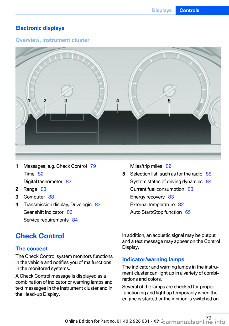
Overview, instrument cluster1Messages, e.g. Check Control 79
Time 82
Digital tachometer 822Range 833Computer 884Transmission display, Drivelogic 83
Gear shift indicator 86
Service requirements 84Miles/trip miles 825Selection list, such as for the radio 88
System states of driving dynamics 84
Current fuel consumption 83
Energy recovery 83
External temperature 82
Auto Start/Stop function 65Check Control
The concept The Check Control system monitors functions
in the vehicle and notifies you of malfunctions
in the monitored systems.
A Check Control message is displayed as a
combination of indicator or warning lamps and
text messages in the instrument cluster and in
the Head-up Display.In addition, an acoustic signal may be output
and a text message may appear on the Control Display.
Indicator/warning lamps The indicator and warning lamps in the instru‐
ment cluster can light up in a variety of combi‐
nations and colors.
Several of the lamps are checked for proper
functioning and light up temporarily when the
engine is started or the ignition is switched on.Seite 79DisplaysControls79
Online Edition for Part no. 01 40 2 909 953 - VI/13
Page 85 of 230
The supplementary text of urgent messages is
automatically displayed on the Control Display.
Symbols
Depending on the Check Control message, the
following functions can be selected.▷ "Owner's Manual"
Display additional information about the
Check Control message in the Integrated
Owner's Manual.▷ "Service request"
Contact the service partner.▷ "Roadside Assistance"
Contact Roadside Assistance.
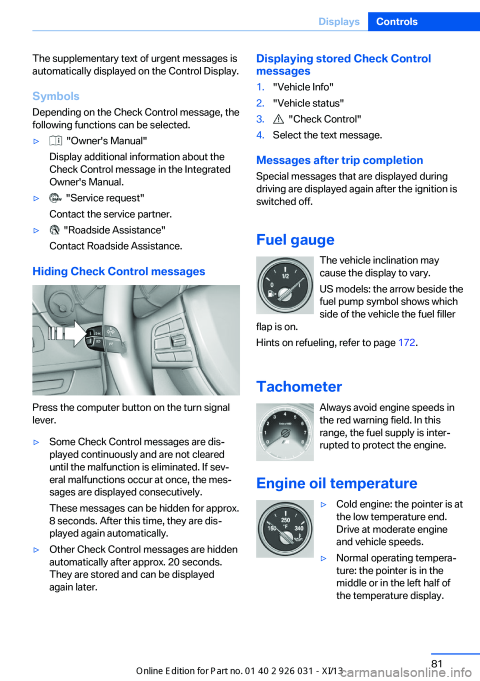
Hiding Check Control messages
Press the computer button on the turn signal
lever.
▷Some Check Control messages are dis‐
played continuously and are not cleared
until the malfunction is eliminated. If sev‐
eral malfunctions occur at once, the mes‐
sages are displayed consecutively.
These messages can be hidden for approx.
8 seconds. After this time, they are dis‐
played again automatically.▷Other Check Control messages are hidden
automatically after approx. 20 seconds.
They are stored and can be displayed
again later.Displaying stored Check Control
messages1."Vehicle Info"2."Vehicle status"3. "Check Control"4.Select the text message.
Messages after trip completion
Special messages that are displayed during
driving are displayed again after the ignition is
switched off.
Fuel gauge The vehicle inclination may
cause the display to vary.
US models: the arrow beside the
fuel pump symbol shows which
side of the vehicle the fuel filler
flap is on.
Hints on refueling, refer to page 172.
Tachometer Always avoid engine speeds inthe red warning field. In this
range, the fuel supply is inter‐
rupted to protect the engine.
Engine oil temperature
▷Cold engine: the pointer is at
the low temperature end.
Drive at moderate engine
and vehicle speeds.▷Normal operating tempera‐
ture: the pointer is in the
middle or in the left half of
the temperature display.Seite 81DisplaysControls81
Online Edition for Part no. 01 40 2 909 953 - VI/13
Page 86 of 230
▷Hot engine: the pointer is at the high tem‐
perature end. A Check Control message is
also displayed.
Coolant temperature
If the coolant along with the engine becomes
too hot, a Check Control message is displayed.
Check the coolant level, refer to page 189.
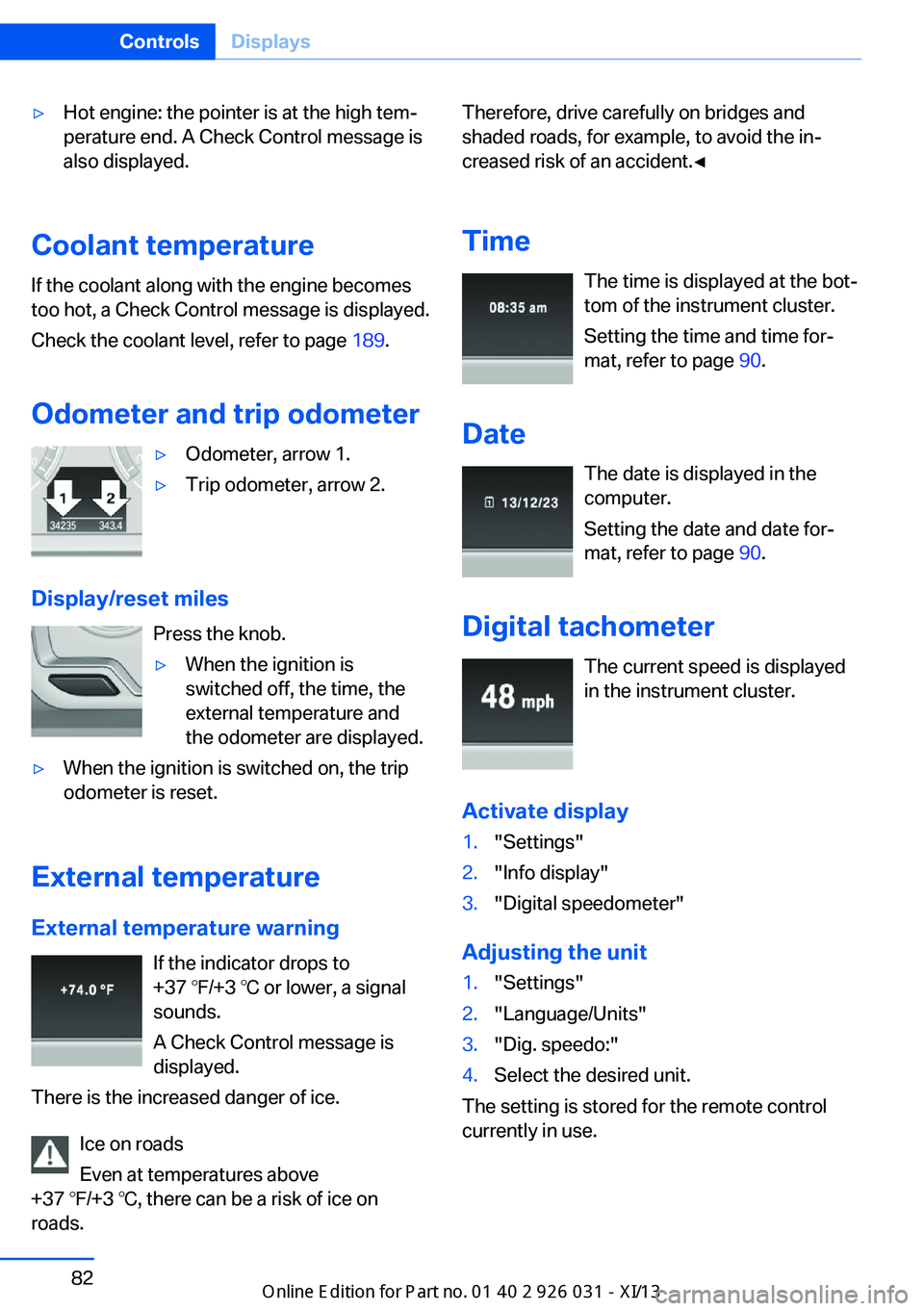
Odometer and trip odometer
▷Odometer, arrow 1.▷Trip odometer, arrow 2.
Display/reset miles Press the knob.
▷When the ignition is
switched off, the time, the
external temperature and
the odometer are displayed.▷When the ignition is switched on, the trip
odometer is reset.
External temperature
External temperature warning If the indicator drops to
+37 ℉/+3 ℃ or lower, a signal
sounds.
A Check Control message is displayed.
There is the increased danger of ice.
Ice on roads
Even at temperatures above
+37 ℉/+3 ℃, there can be a risk of ice on
roads.
Therefore, drive carefully on bridges and
shaded roads, for example, to avoid the in‐
creased risk of an accident.◀
Time The time is displayed at the bot‐
tom of the instrument cluster.
Setting the time and time for‐
mat, refer to page 90.
Date The date is displayed in the
computer.
Setting the date and date for‐
mat, refer to page 90.
Digital tachometer The current speed is displayed
in the instrument cluster.
Activate display1."Settings"2."Info display"3."Digital speedometer"
Adjusting the unit
1."Settings"2."Language/Units"3."Dig. speedo:"4.Select the desired unit.
The setting is stored for the remote control
currently in use.
Seite 82ControlsDisplays82
Online Edition for Part no. 01 40 2 909 953 - VI/13
Page 93 of 230
When destination guidance is activated in
the navigation system.
When the arrow view in the Head-up Dis‐
play is inactive.
Adjusting the info display
You can select what information from the on‐
board computer is to be displayed on the info
display of the instrument cluster.
1."Settings"2."Info display"3.Select the desired displays.
Information in detail
Range
Displays the estimated cruising range available
with the remaining fuel.
It is calculated based on your driving style over
the last 20 miles/30 km.
Average fuel consumption
The average fuel consumption is calculated for
the period during which the engine is running.
The average fuel consumption is calculated for
the distance traveled since the last reset by the
onboard computer.
Average speed
Periods in which the vehicle is parked with the
engine manually stopped do not enter into the
calculation of the average speed.
Resetting average values
Press and hold the computer button on the turn signal lever.
Distance to destination
The distance remaining to the destination is
displayed if a destination is entered in the navi‐
gation system before the trip is started.
The distance to the destination is adopted au‐
tomatically.
Time of arrival
The estimated time of arrival is
displayed if a destination is en‐
tered in the navigation system
before the trip is started.
The time must be correctly set.
Speed limit detection
Description of the speed limit detection, refer
to page 86, function.
Speed limit
Display of a speed limit which, when reached,
should cause a warning to be issued.
The warning is repeated if the vehicle speed
drops below the set speed limit once by at least 3 mph/5 km/h.
Displaying, setting or changing the
limit1."Settings"2."Speed"3."Warning at:"4.Turn the controller until the desired limit is
displayed.5.Press the controller.
The speed limit is stored.
Activating/deactivating the limit
1."Settings"2."Speed"3."Warning"4.Press the controller.
Setting your current speed as the limit
1."Settings"2."Speed"3."Select current speed"4.Press the controller.Seite 89DisplaysControls89
Online Edition for Part no. 01 40 2 909 953 - VI/13
Page 94 of 230
The current vehicle speed is stored as the
limit.
Trip computer
The vehicle features two types of computer.
▷"Onboard info": the values can be reset as
often as necessary.▷"Trip computer": the values provide an
overview of the current trip.
Resetting the trip computer
1."Vehicle Info"2."Trip computer"3."Reset": all values are reset.
"Automatically reset": all values are reset
approx. 4 hours after the vehicle comes to
a standstill.
Display on the Control Display
Display the onboard computer or trip computer
on the Control Display.
1."Vehicle Info"2."Onboard info" or "Trip computer"
Resetting the fuel consumption or
speed
1."Vehicle Info"2."Onboard info"3."Consumpt." or "Speed"4."Yes"
Settings on the Control
Display
Time
Setting the time zone
1."Settings"2."Time/Date"3."Time zone"4.Select the desired time zone.
The time zone is stored.
Setting the time
1."Settings"2."Time/Date"3."Time:"4.Turn the controller until the desired hours
are displayed.5.Press the controller.6.Turn the controller until the desired mi‐
nutes are displayed.7.Press the controller.
The time is stored.
Setting the time format
1."Settings"2."Time/Date"3."Format:"4.Select the desired format.
The time format is stored.
Date
Setting the date
1."Settings"2."Time/Date"3."Date:"4.Turn the controller until the desired day is
displayed.5.Press the controller.6.Make the necessary settings for the month
and year.
The date is stored.
Setting the date format
1."Settings"2."Time/Date"Seite 90ControlsDisplays90
Online Edition for Part no. 01 40 2 909 953 - VI/13
Page 228 of 230
Tow fitting 203
Towing 202
Tow-starting 202
Tow truck 202
TPM Tire Pressure Moni‐ tor 100
Transmission, manual 77
Transmission positions 72
Transporting children safely 59
Tread, tires 178
Trip computer 90
Triple turn signal activa‐ tion 69
Trip odometer 82
Truck for tow-starting/ towing 202
Trunk lid 36
Trunk lid, automatic 37
Trunk lid, emergency unlock‐ ing 39
Trunk lid, hotel function 38
Trunk lid opening/closing with no-touch activation 40
Trunk lid via remote con‐ trol 34
Turning circle 213
Turning circle lines, rearview camera 127
Turn signals, operation 69
Turn signals, rear, bulb re‐ placement 195
U
Unintentional alarm 43
Units of measure 91
Universal remote control 141
Unlocking/locking from in‐ side 36
Unlocking/locking via door lock 35
Unlocking/locking with re‐ mote control 34
Unlocking, settings 41 Updates made after the edito‐
rial deadline 7
Upholstery care 207
USB interface 146
V
V8 high-performance engine, High-performance engine
V8 158
Vehicle battery 197
Vehicle battery, replac‐ ing 197
Vehicle, breaking in 160
Vehicle care 206
Vehicle equipment 6
Vehicle identification number, refer to Identification num‐
ber in the engine compart‐
ment 184
Vehicle jack 197
Vehicle paint 206
Vehicle storage 208
Vehicle wash 205
Ventilation 137
Ventilation, refer to Parked- car ventilation 139
Voice activation system 23
W Warning indicators 79
Warning lamps 79
Warning messages, refer to Check Control 79
Warning triangle 200
Washer fluid 71
Washer fluid reservoir, ca‐ pacity 214
Washer nozzles, wind‐ shield 71
Washer system 69
Washing, vehicle 205
Water on roads 162
Weights 213
Welcome lamps 92 Wheel base, vehicle 213
Wheel cleaner 207
Wheels, changing 179
Wheels, everything on wheels and tires 175
Wheels, Flat Tire Monitor FTM 102
Wheels, Tire Pressure Moni‐ tor TPM 100
Width, vehicle 212
Window defroster, rear 136
Windows, powered 43
Windshield, climate con‐ trol 161
Windshield washer fluid 71
Windshield washer noz‐ zles 71
Windshield washer sys‐ tem 69
Windshield wiper 69
Windshield wipers, fold-out position 71
Winter storage, care 208
Winter tires, suitable tires 180
Winter tires, tread 178
Wiper blades, replacing 192
Wiper fluid 71
Wiper system 69
Wood, care 207
Word match concept, naviga‐ tion 22
Wrench 192
X Xenon headlamps, bulb re‐ placement 193 Seite 224ReferenceEverything from A to Z224
Online Edition for Part no. 01 40 2 909 953 - VI/13