ESP BMW M5 2014 F10M Service Manual
[x] Cancel search | Manufacturer: BMW, Model Year: 2014, Model line: M5, Model: BMW M5 2014 F10MPages: 237, PDF Size: 5.21 MB
Page 131 of 237
Driving stability control systemsVehicle features and optionsThis chapter describes all standard, country-
specific and optional features offered with the
series. It also describes features that are not
necessarily available in your car, e. g., due to
the selected options or country versions. This
also applies to safety-related functions and
systems.
Antilock Brake System ABS
ABS prevents locking of the wheels during
braking.
The vehicle contains its steering power even
during full brake applications, thus increasing
active safety.
ABS is operational every time you start the en‐
gine.
Brake assistant
When you apply the brakes rapidly, this system
automatically produces the greatest possible
braking force boost. It reduces the braking dis‐
tance to a minimum during emergency stop.
This system utilizes all of the benefits provided
by ABS.
Do not reduce the pressure on the brake pedal
for the duration of the emergency stop.
Drive-off assistant
This system supports driving off on inclines.
The parking brake is not required.1.Hold the vehicle in place with the foot
brake.2.Release the foot brake and drive off with‐
out delay.After the foot brake is released, the vehicle is
held in place for approx. 2 seconds.
Depending on the vehicle load or when a trailer
is used, the vehicle may roll back slightly.
Driving off without delay
After releasing the foot brake, start driv‐
ing without delay, since the drive-off assistant
will not hold the vehicle in place for more than
approx. 2 seconds and the vehicle will begin to
roll back.◀
DSC Dynamic Stability
Control
The concept DSC prevents traction loss in the power
wheels when driving off and accelerating.
DSC also recognizes unstable vehicle condi‐
tions such as fishtailing or nose-diving. Within
the physical limits DSC helps to keep the vehi‐
cle on a steady course by reducing engine
speed and by applying brakes to the individual
wheels.
Note Adjust your driving style to the situation
An appropriate driving style is always the
responsibility of the driver.
The laws of physics cannot be repealed, not
even with DSC.
Therefore, do not reduce the additional safety
margin by driving in a risky manner.◀
Do not deactivate DSC when driving with
roof load
Do not deactivate Dynamic Stability Control DSC when driving with roof load, e.g. roof-
mounted luggage rack.Seite 127Driving stability control systemsControls127
Online Edition for Part no. 0140 2 956 245 - X/14
Page 132 of 237
Otherwise, driving safety is not given in driv‐
ing-critical situation due to the elevated center
of gravity.◀
At a glance
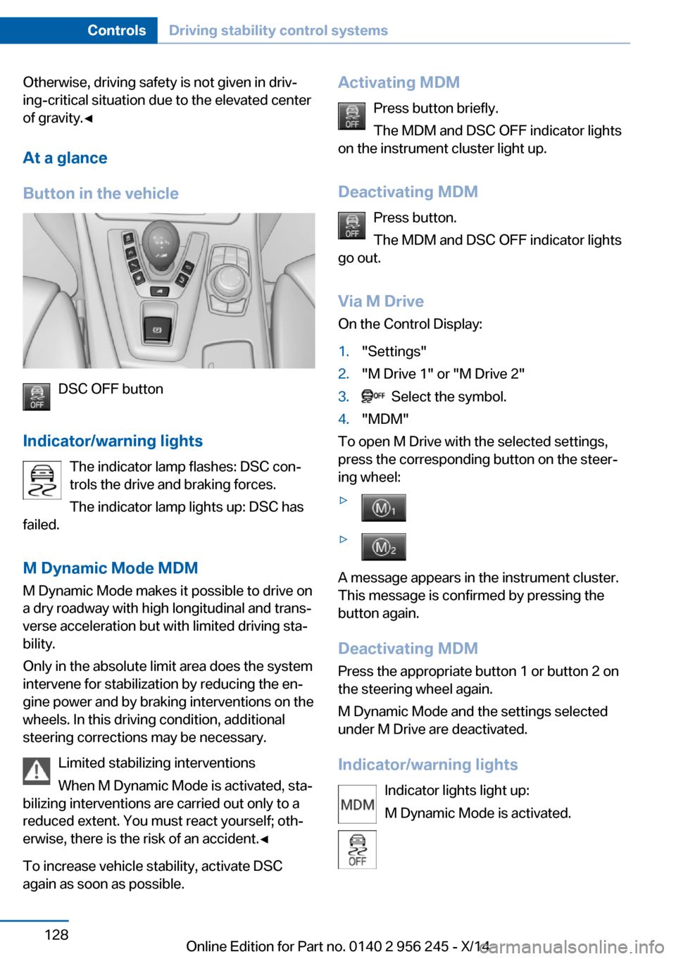
Button in the vehicle
DSC OFF button
Indicator/warning lights The indicator lamp flashes: DSC con‐
trols the drive and braking forces.
The indicator lamp lights up: DSC has
failed.
M Dynamic Mode MDM
M Dynamic Mode makes it possible to drive on
a dry roadway with high longitudinal and trans‐
verse acceleration but with limited driving sta‐
bility.
Only in the absolute limit area does the system
intervene for stabilization by reducing the en‐
gine power and by braking interventions on the
wheels. In this driving condition, additional
steering corrections may be necessary.
Limited stabilizing interventions
When M Dynamic Mode is activated, sta‐
bilizing interventions are carried out only to a
reduced extent. You must react yourself; oth‐
erwise, there is the risk of an accident.◀
To increase vehicle stability, activate DSC
again as soon as possible.
Activating MDM
Press button briefly.
The MDM and DSC OFF indicator lights
on the instrument cluster light up.
Deactivating MDM Press button.
The MDM and DSC OFF indicator lights
go out.
Via M Drive On the Control Display:1."Settings"2."M Drive 1" or "M Drive 2"3. Select the symbol.4."MDM"
To open M Drive with the selected settings,
press the corresponding button on the steer‐
ing wheel:
▷▷
A message appears in the instrument cluster.
This message is confirmed by pressing the
button again.
Deactivating MDM
Press the appropriate button 1 or button 2 on
the steering wheel again.
M Dynamic Mode and the settings selected
under M Drive are deactivated.
Indicator/warning lights Indicator lights light up:
M Dynamic Mode is activated.
Seite 128ControlsDriving stability control systems128
Online Edition for Part no. 0140 2 956 245 - X/14
Page 133 of 237
DSC indicator lamp also flashes:
M Dynamic Mode controls the drive
forces and brake forces.
Indicator lights light up:
M Dynamic Mode or DSC has failed.
Deactivating DSC: DSC OFF
When DSC is deactivated, driving stability is
reduced during acceleration and when driving in curves.
To increase vehicle stability, activate DSC
again as soon as possible.
Deactivating DSC Press and hold this button but not longer
than approx. 10 seconds, until the indica‐
tor lamp for DSC OFF lights up in the instru‐
ment cluster and displays DSC OFF.
The DSC system is switched off.
Activating DSC Press button.
DSC OFF and the DSC OFF indicator
lamp go out.
Via M DriveOn the Control Display:1."Settings"2."M Drive 1" or "M Drive 2"3. Select the symbol.4."DSC OFF"
To open M Drive with the selected settings,
press the corresponding button on the steer‐
ing wheel:
▷▷
A message appears in the instrument cluster.
This message is confirmed by pressing the
button again.
Indicator/warning lights
When DSC is deactivated, DSC OFF is dis‐
played in the instrument cluster.
The indicator lamp lights up: DSC is
deactivated.
Active M differential The concept The active M differential assures continuously
variable locking of the rear axle differential de‐
pending on the driving situation. This prevents
individual rear wheels from spinning even
when DSC is switched off and in M Dynamic
Mode, so that optimum traction is always as‐
sured in all driving situations.
The driver is responsible adapting his or her
driving behavior to the situation.
Dynamic Damping Control The conceptThis system reduces undesirable vehicle mo‐
tion when using a dynamic driving style or trav‐
eling on uneven road surfaces.
The system enhances driving dynamics and
comfort fitting road surface and driving style.
Programs Setting options for calibrating the shock ab‐
sorbers:
▷"Comfort": comfort-oriented.▷"Sport": balanced out.▷"Sport Plus": consistently sporty.Seite 129Driving stability control systemsControls129
Online Edition for Part no. 0140 2 956 245 - X/14
Page 134 of 237

Selecting a channel
Via M Drive On the Control Display:1."Settings"2."M Drive 1" or "M Drive 2"3. Select the symbol.4.Select the desired channel.
When M Drive is active, setting is immedi‐
ately applied.
To activate M Drive with the selected settings,
press the corresponding button on the steer‐
ing wheel:
▷▷
Using the button
Press button repeatedly until the desired
program is displayed in the instrument
cluster.
Display in the instrument cluster Dynamic Damping Control with se‐
lected program with activated display
of the system states of the driving dy‐
namics, refer to page 90.
Servotronic
The concept
The Servotronic varies the steering force re‐
quired to turn the wheels in accordance with
the vehicle speed. At low speeds, the steering
force is strongly supported, i. e. during steer‐
ing, low force is required. As the speed in‐
creases, the assistance of the steering force is
reduced.
Furthermore, the steering force adapts accord‐
ing to the driving program, so that a direct,
sporty feel and/or comfortable steering is con‐
veyed.
Programs Steering force setting options:▷"Comfort": low.▷"Sport": medium.▷"Sport Plus": high.
Selecting a channel
Via M Drive On the Control Display:
1."Settings"2."M Drive 1" or "M Drive 2"3. Select the symbol.4.Select the desired channel.
When M Drive is active, setting is immedi‐
ately applied.
To activate M Drive with the selected settings,
press the corresponding button on the steer‐
ing wheel:
▷▷Seite 130ControlsDriving stability control systems130
Online Edition for Part no. 0140 2 956 245 - X/14
Page 138 of 237
ment cluster indicates whether the system is
switched on.
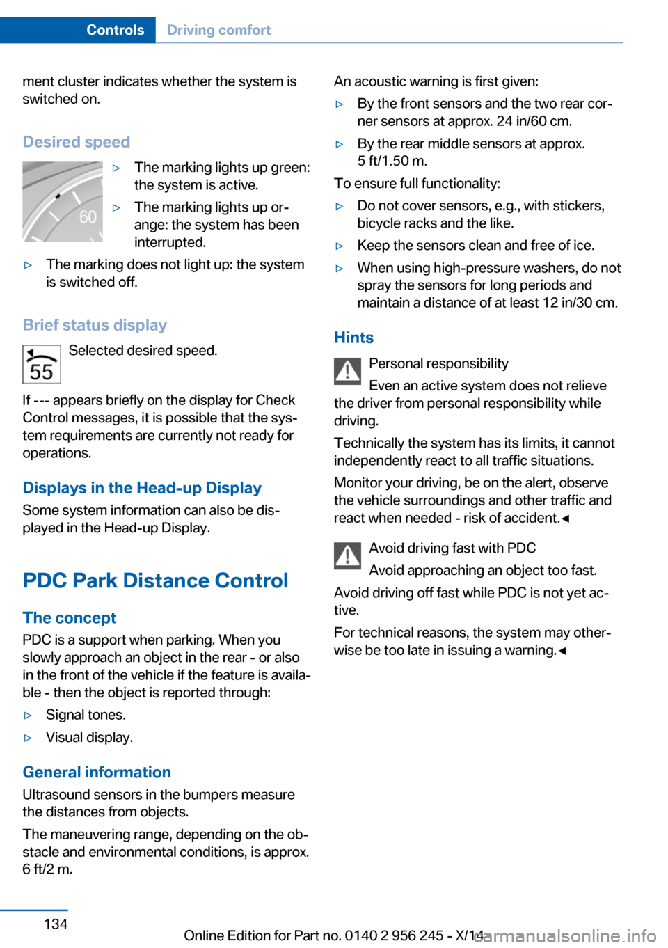
Desired speed▷The marking lights up green:
the system is active.▷The marking lights up or‐
ange: the system has been
interrupted.▷The marking does not light up: the system
is switched off.
Brief status display
Selected desired speed.
If --- appears briefly on the display for Check
Control messages, it is possible that the sys‐
tem requirements are currently not ready for
operations.
Displays in the Head-up Display Some system information can also be dis‐played in the Head-up Display.
PDC Park Distance Control
The concept PDC is a support when parking. When you
slowly approach an object in the rear - or also
in the front of the vehicle if the feature is availa‐
ble - then the object is reported through:
▷Signal tones.▷Visual display.
General information
Ultrasound sensors in the bumpers measure
the distances from objects.
The maneuvering range, depending on the ob‐
stacle and environmental conditions, is approx.
6 ft/2 m.
An acoustic warning is first given:▷By the front sensors and the two rear cor‐
ner sensors at approx. 24 in/60 cm.▷By the rear middle sensors at approx.
5 ft/1.50 m.
To ensure full functionality:
▷Do not cover sensors, e.g., with stickers,
bicycle racks and the like.▷Keep the sensors clean and free of ice.▷When using high-pressure washers, do not
spray the sensors for long periods and
maintain a distance of at least 12 in/30 cm.
Hints
Personal responsibility
Even an active system does not relieve
the driver from personal responsibility while
driving.
Technically the system has its limits, it cannot
independently react to all traffic situations.
Monitor your driving, be on the alert, observe
the vehicle surroundings and other traffic and
react when needed - risk of accident.◀
Avoid driving fast with PDC
Avoid approaching an object too fast.
Avoid driving off fast while PDC is not yet ac‐
tive.
For technical reasons, the system may other‐
wise be too late in issuing a warning.◀
Seite 134ControlsDriving comfort134
Online Edition for Part no. 0140 2 956 245 - X/14
Page 142 of 237
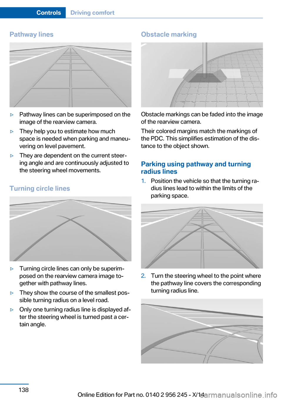
Pathway lines▷Pathway lines can be superimposed on the
image of the rearview camera.▷They help you to estimate how much
space is needed when parking and maneu‐
vering on level pavement.▷They are dependent on the current steer‐
ing angle and are continuously adjusted to
the steering wheel movements.
Turning circle lines
▷Turning circle lines can only be superim‐
posed on the rearview camera image to‐
gether with pathway lines.▷They show the course of the smallest pos‐
sible turning radius on a level road.▷Only one turning radius line is displayed af‐
ter the steering wheel is turned past a cer‐
tain angle.Obstacle marking
Obstacle markings can be faded into the image
of the rearview camera.
Their colored margins match the markings of
the PDC. This simplifies estimation of the dis‐
tance to the object shown.
Parking using pathway and turning
radius lines
1.Position the vehicle so that the turning ra‐
dius lines lead to within the limits of the
parking space.2.Turn the steering wheel to the point where
the pathway line covers the corresponding
turning radius line.Seite 138ControlsDriving comfort138
Online Edition for Part no. 0140 2 956 245 - X/14
Page 149 of 237
Ice and condensation are quickly removed
from the windshield and the front side win‐
dows.
For this purpose, point the side vents onto the
side windows as needed.
Adjust air flow with the program active.
If the windows are fogged over, you can also
reel on the cooling function or press the AUTO
button to utilize the condensation sensor.
Maximum cooling Press button.
The system is set to the lowest tem‐
perature, optimum air flow and air circulation
mode.
Air flows out of the vents to the upper body re‐
gion. The vents need to be open for this.
The function is available above an external
temperature of approx. 32 ℉/0 ℃ and with the
engine running is indicated.
Adjust air flow with the program active.
Automatic recirculated-air control/
recirculated-air mode
You may respond to unpleasant odors or pollu‐
tants in the immediate environment by tempo‐
rarily suspending the supply of outside air. The
system then recirculates the air currently
within the vehicle.
Press button repeatedly to select an
operating mode:▷LEDs off: outside air flows in continuously.▷Left LED on, automatic recirculated-air
control: a sensor detects pollutants in the
outside air and shuts off automatically.▷Right LED on, recirculated-air mode: the
supply of outside air into the vehicle is per‐
manently blocked.
If the windows are fogged over, reel off the re‐
circulated-air mode and press the AUTO but‐
ton on the driver's side to utilize the condensa‐
tion sensor. Make sure that air can flow to the
windshield.
Sufficient ventilation
When remaining in the vehicle for an ex‐
tended period of time, ensure sufficient exter‐
nal ventilation. Do not continuously use recir‐
culated-air mode; otherwise the air quality in
the interior continuously worsens.◀
Cooling function
The car's interior can only be cooled with the
engine running.
Press button.
The air will be cooled and dehumidi‐
fied and, depending on the temperature set‐
ting, warmed again.
Depending on the weather, the windshield and
side windows may fog up briefly when the en‐
gine is started.
The cooling function is switched on automati‐
cally with the AUTO program.
When using the automatic climate control,
condensation water, refer to page 171, devel‐
ops that exits underneath the vehicle.
Rear window defroster Press button.
The rear window defroster switches
off automatically after a certain period of time.
SYNC program The current settings on the driver'sside for temperature, air flow, air distri‐
bution, and AUTO program are transferred to the front passenger side and to the left andright rear.
The program is switched off if the settings on
the front passenger side or in the rear are
changed.Seite 145Climate controlControls145
Online Edition for Part no. 0140 2 956 245 - X/14
Page 160 of 237
middle section is folded down. Otherwise, in‐
jury or damage may result.◀
Ensuring the stability of the child seat
When installing child restraint systems,
make sure that the child seat is securely fas‐
tened to the backrest of the seat. Angle and
headrest of the backrest might need to be ad‐
justed or possibly be removed. Make sure that
all backrests are securely locked. Otherwise
the stability of the child seat can be affected,
and there is an increased risk of injury because
of unexpected movement of the rear seat
backrest.◀
Opening Move the front seats to an upright posi‐
tion
Before folding down the rear backrests, ensure
that the front seats are moved forward slightly
and are in an upright position. Otherwise, the
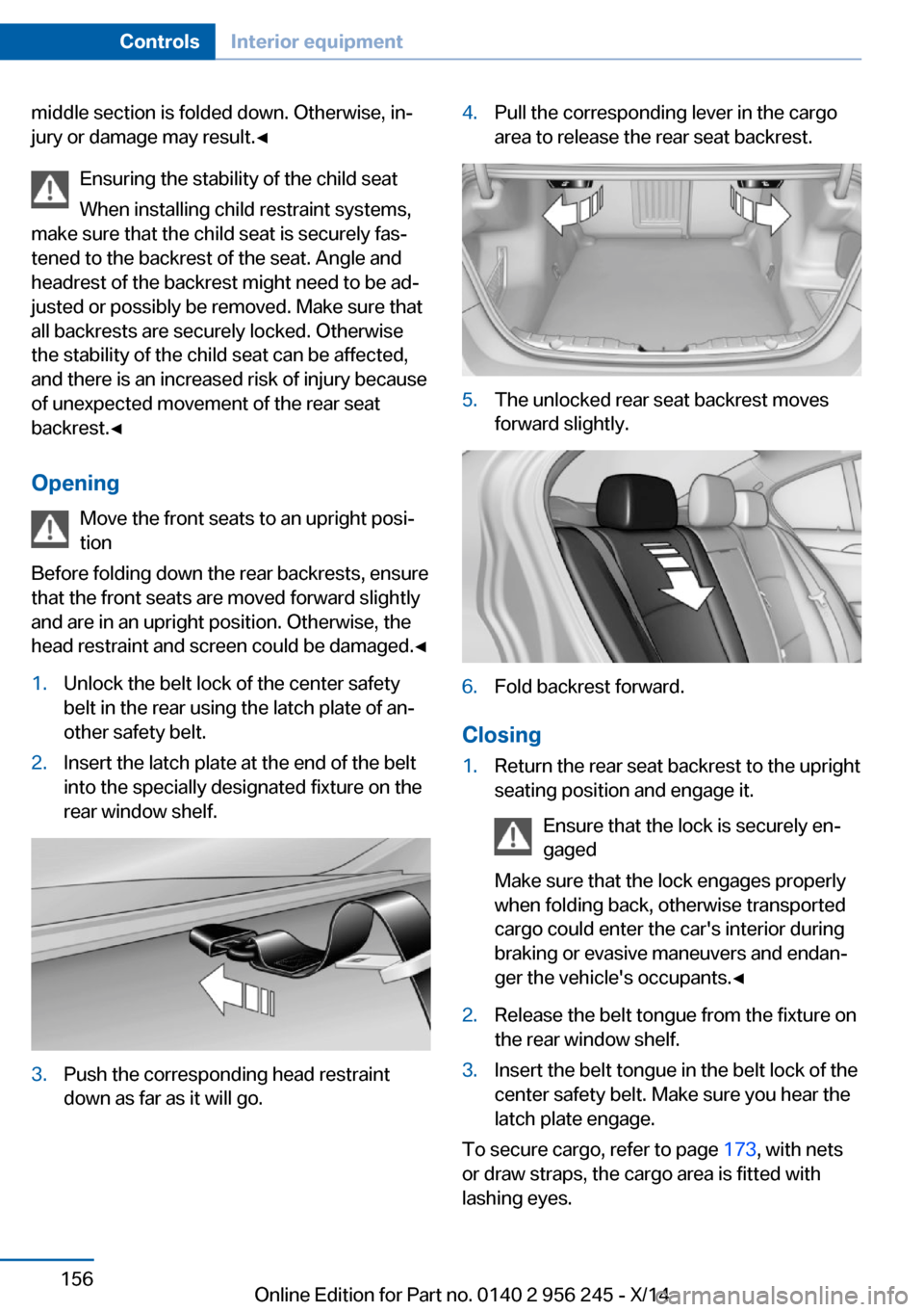
head restraint and screen could be damaged.◀1.Unlock the belt lock of the center safety
belt in the rear using the latch plate of an‐
other safety belt.2.Insert the latch plate at the end of the belt
into the specially designated fixture on the
rear window shelf.3.Push the corresponding head restraint
down as far as it will go.4.Pull the corresponding lever in the cargo
area to release the rear seat backrest.5.The unlocked rear seat backrest moves
forward slightly.6.Fold backrest forward.
Closing
1.Return the rear seat backrest to the upright
seating position and engage it.
Ensure that the lock is securely en‐
gaged
Make sure that the lock engages properly
when folding back, otherwise transported
cargo could enter the car's interior during
braking or evasive maneuvers and endan‐
ger the vehicle's occupants.◀2.Release the belt tongue from the fixture on
the rear window shelf.3.Insert the belt tongue in the belt lock of the
center safety belt. Make sure you hear the
latch plate engage.
To secure cargo, refer to page 173, with nets
or draw straps, the cargo area is fitted with
lashing eyes.
Seite 156ControlsInterior equipment156
Online Edition for Part no. 0140 2 956 245 - X/14
Page 170 of 237
BMW M5 technologyVehicle features and options
This chapter describes all standard, country-
specific and optional features offered with the
series. It also describes features that are not
necessarily available in your car, e. g., due to
the selected options or country versions. This
also applies to safety-related functions and
systems.
V8 high-performance engine
The high-performance V8 engine gets a maxi‐
mum power of 412 kW, with Competition
Package 423 kW, from a displacement of
4.4 liters and a maximum torque of 680 Nm.
With its spontaneous response behavior, a
speed range of wide utility results. The maxi‐
mum engine speed is 7,200 rpm and is elec‐
tronically controlled. Because of the high en‐
gine dynamics, the maximum engine speed
with the vehicle stationary is reduced.
Warm-up
During the engine warm-up phase, the
V8 high-performance engine has a somewhat
rougher running behavior because of the emis‐
sion controls.
When the engine is cold, the exhaust system
has a slightly metallic undertone due to the na‐
ture of the system.
For more information about the warm-up pro‐
cedure: Engine speed, refer to page 87, and
engine oil temperature, refer to page 88.
Compound brake
The high-performance braking system has
perforated compound brake discs.
Because of particular structural characteristics,
there may be operation-related noises duringbraking. However, this has no effect on per‐
formance, operational reliability and reliability
of the brake.
Correct braking To keep the brake system in optimum condi‐
tion, it is expedient to apply them at regular in‐
tervals corresponding to the vehicle character.
M carbon ceramic brake
The high-performance braking system has
perforated carbon-ceramic brake disks and is
designed for use on racetracks.
Due to properties of the materials used, brak‐
ing may be associated with louder function
noises, particularly in wet conditions, just be‐
fore the vehicle comes to a stop. However, this
has no effect on the performance, operational
reliability and durability of the brake.
The effects of moisture and road salt, from us‐
ing a carwash or dew formation overnight e.g.,
may render the braking effect comparable to
that of a conventional braking system. This
may be perceived as reduced braking effect
and can be compensated for if needed by
pressing the brake pedal harder.
Before washing the vehicle in an automatic
carwash or wash tunnel, clean the brake discs
and brake calipers with a steam jet or high-
pressure washer as well, to prevent encrusta‐
tions and dirt buildups, caused by salt crystals,
e.g., if the car is immobile afterwards. The
cleaning effect of automatic carwashes or
wash tunnels is usually not adequate for this in
the area around the wheels.
To do this, also follow the instructions in
Washing the vehicle, refer to page 214, and
Braking safely, refer to page 170.Seite 166Driving tipsBMW M5 technology166
Online Edition for Part no. 0140 2 956 245 - X/14
Page 174 of 237
This phenomenon is referred to as hydroplan‐
ing. It is characterized by a partial or complete
loss of contact between the tires and the road
surface, ultimately undermining your ability to
steer and brake the vehicle.
Driving through water Observe water level and speed
Do not exceed the maximum water level
and maximum speed; otherwise, the vehicle's
engine, the electrical systems and the trans‐
mission may be damaged.◀
Drive though calm water only and only if it is
not deeper than 9.8 inches/25 cm and at this
height, no faster than walking speed, up to
3 mph/5 km/h.
Braking safely
Your vehicle is equipped with ABS as a stand‐
ard feature.
Applying the brakes fully is the most effective
way of braking in situations needed.
Steering is still responsive. You can still avoid
any obstacles with a minimum of steering ef‐
fort.
The pulsing of the brake pedal indicates that
ABS is in its active mode.
In certain braking situations, the perforated
brake discs can cause functional problems.
However, this has no effect on the perform‐
ance and operational reliability of the brake.
Objects within the range of movement
of the pedals
No objects in the area around the pedals
Keep floor mats, carpets, and any other
objects out of the pedal area; otherwise, the
function of the pedals could be impeded while driving and create the risk of an accident.
Do not place additional floor mats over existing
mats or other objects.Only use floor mats that have been approved
for the vehicle and can be properly attached to
floor.
Ensure that the floor mats are securely fas‐
tened again after they were removed for clean‐
ing, e.g.◀
Driving in wet conditions When roads are wet, salted, or in heavy rain,
press brake pedal ever so gently every few
miles.
Ensure that this action does not endanger other traffic.
The heat generated in this process helps dry
the brake discs and pads.
In this way braking efficiency will be available
when you need it.
Hills Avoid stressing the brakes
Avoid placing excessive stress on the
brake system. Light but consistent brake pres‐
sure can lead to high temperatures, brakes
wearing out and possibly even brake failure.◀
Do not drive in neutral
Do not drive in neutral or with the engine
stopped, as doing so disables engine braking.
In addition, steering and brake assist are un‐
available with the engine stopped.◀
Drive long or steep downhill gradients in the
gear that requires least braking efforts. Other‐
wise the brakes may overheat and reduce
brake efficiency.
Manual transmission:
You can increase the engine's braking effect
by shifting down, going all the way to first gear,
if needed.
M double-clutch transmission:
You can increase the engine's braking effect
by shifting down in sequential mode, refer to
page 78.Seite 170Driving tipsThings to remember when driving170
Online Edition for Part no. 0140 2 956 245 - X/14