park assist BMW M5 SEDAN 2013 Owners Manual
[x] Cancel search | Manufacturer: BMW, Model Year: 2013, Model line: M5 SEDAN, Model: BMW M5 SEDAN 2013Pages: 230, PDF Size: 6.29 MB
Page 17 of 230
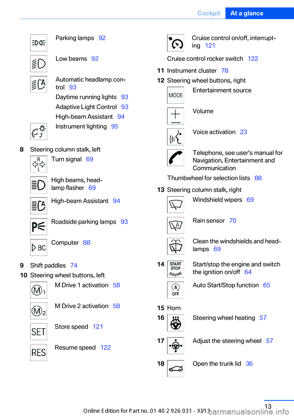
Parking lamps 92Low beams 92Automatic headlamp con‐
trol 93
Daytime running lights 93
Adaptive Light Control 93
High-beam Assistant 94Instrument lighting 958Steering column stalk, leftTurn signal 69High beams, head‐
lamp flasher 69High-beam Assistant 94Roadside parking lamps 93Computer 889Shift paddles 7410Steering wheel buttons, leftM Drive 1 activation 58M Drive 2 activation 58Store speed 121Resume speed 122Cruise control on/off, interrupt‐
ing 121Cruise control rocker switch 12211Instrument cluster 7812Steering wheel buttons, rightEntertainment sourceVolumeVoice activation 23Telephone, see user's manual for
Navigation, Entertainment and
CommunicationThumbwheel for selection lists 8813Steering column stalk, rightWindshield wipers 69Rain sensor 70Clean the windshields and head‐
lamps 6914Start/stop the engine and switch
the ignition on/off 64Auto Start/Stop function 6515Horn16Steering wheel heating 5717Adjust the steering wheel 5718Open the trunk lid 36Seite 13CockpitAt a glance13
Online Edition for Part no. 01 40 2 909 953 - VI/13
Page 84 of 230
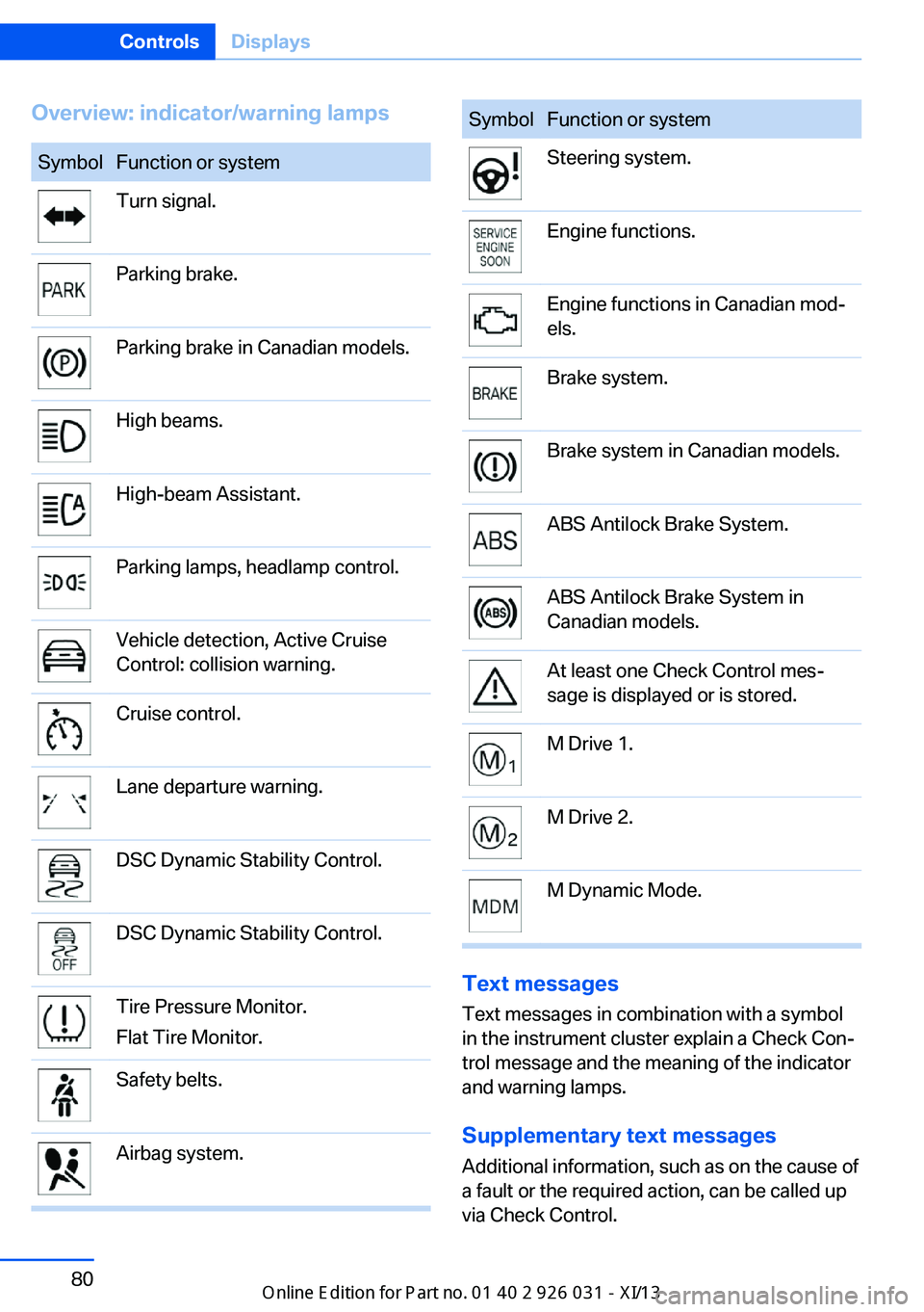
Overview: indicator/warning lampsSymbolFunction or systemTurn signal.Parking brake.Parking brake in Canadian models.High beams.High-beam Assistant.Parking lamps, headlamp control.Vehicle detection, Active Cruise
Control: collision warning.Cruise control.Lane departure warning.DSC Dynamic Stability Control.DSC Dynamic Stability Control.Tire Pressure Monitor.
Flat Tire Monitor.Safety belts.Airbag system.SymbolFunction or systemSteering system.Engine functions.Engine functions in Canadian mod‐
els.Brake system.Brake system in Canadian models.ABS Antilock Brake System.ABS Antilock Brake System in
Canadian models.At least one Check Control mes‐
sage is displayed or is stored.M Drive 1.M Drive 2.M Dynamic Mode.
Text messages
Text messages in combination with a symbol
in the instrument cluster explain a Check Con‐ trol message and the meaning of the indicator
and warning lamps.
Supplementary text messages
Additional information, such as on the cause of
a fault or the required action, can be called up
via Check Control.
Seite 80ControlsDisplays80
Online Edition for Part no. 01 40 2 909 953 - VI/13
Page 96 of 230
LampsVehicle equipment
All standard, country-specific and optional
equipment that is offered in the model series is
described in this chapter. Therefore, equip‐
ment is also described that is not available in a
vehicle, e. g., because of the selected optional
equipment or country variant. This also applies
for safety-related functions and systems.
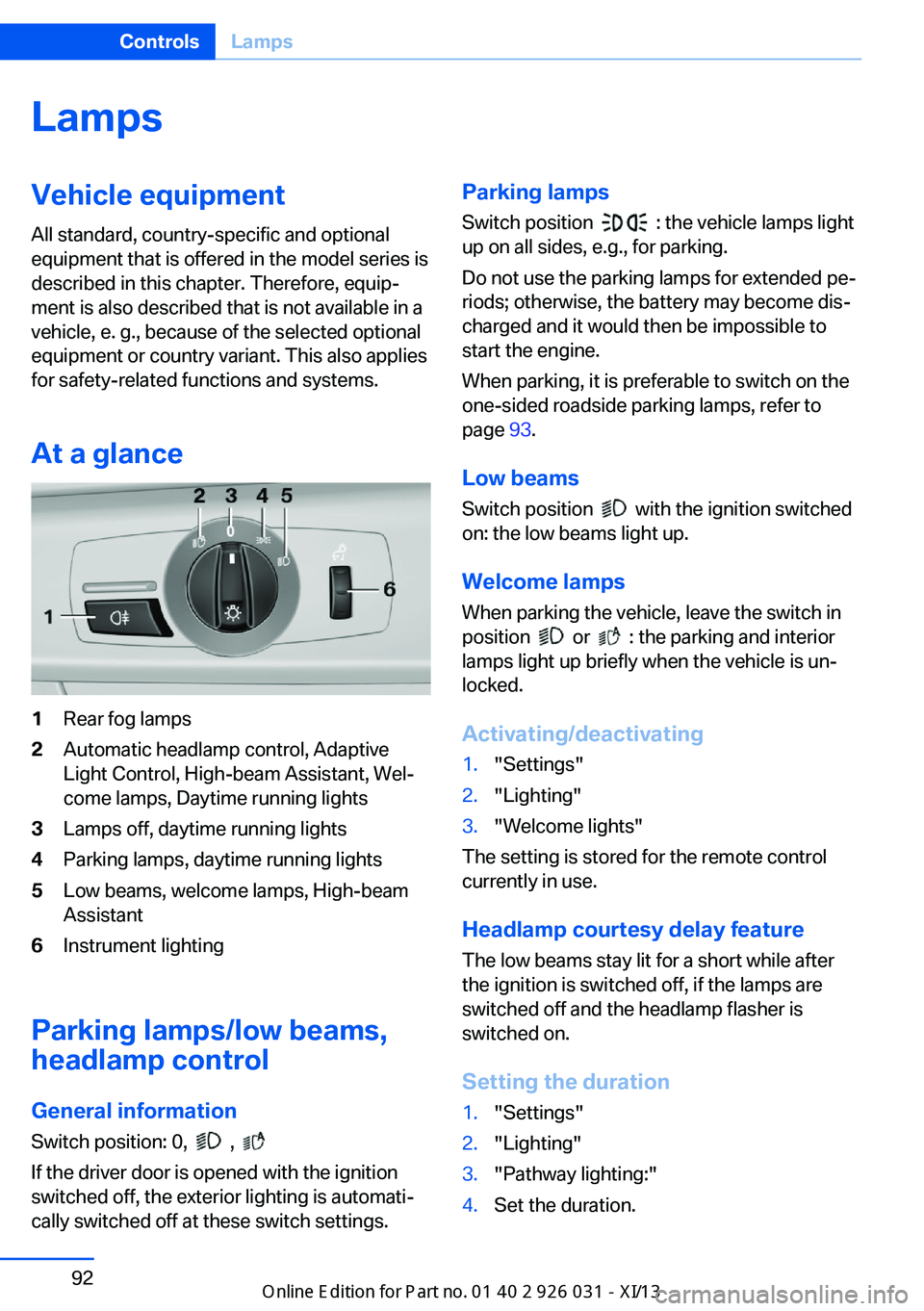
At a glance1Rear fog lamps2Automatic headlamp control, Adaptive
Light Control, High-beam Assistant, Wel‐
come lamps, Daytime running lights3Lamps off, daytime running lights4Parking lamps, daytime running lights5Low beams, welcome lamps, High-beam
Assistant6Instrument lighting
Parking lamps/low beams,
headlamp control
General information Switch position: 0,
,
If the driver door is opened with the ignition
switched off, the exterior lighting is automati‐
cally switched off at these switch settings.
Parking lamps
Switch position
: the vehicle lamps light
up on all sides, e.g., for parking.
Do not use the parking lamps for extended pe‐
riods; otherwise, the battery may become dis‐
charged and it would then be impossible to
start the engine.
When parking, it is preferable to switch on the
one-sided roadside parking lamps, refer to
page 93.
Low beams Switch position
with the ignition switched
on: the low beams light up.
Welcome lamps When parking the vehicle, leave the switch in
position
or : the parking and interior
lamps light up briefly when the vehicle is un‐
locked.
Activating/deactivating
1."Settings"2."Lighting"3."Welcome lights"
The setting is stored for the remote control
currently in use.
Headlamp courtesy delay feature
The low beams stay lit for a short while after
the ignition is switched off, if the lamps are
switched off and the headlamp flasher is
switched on.
Setting the duration
1."Settings"2."Lighting"3."Pathway lighting:"4.Set the duration.Seite 92ControlsLamps92
Online Edition for Part no. 01 40 2 909 953 - VI/13
Page 121 of 230
Driving stability control systemsVehicle equipmentAll standard, country-specific and optional
equipment that is offered in the model series is
described in this chapter. Therefore, equip‐
ment is also described that is not available in a
vehicle, e. g., because of the selected optional
equipment or country variant. This also applies
for safety-related functions and systems.
Antilock Brake System ABS ABS prevents locking of the wheels during
braking.
The vehicle remains steerable even during full
brake applications, thus increasing active
safety.
ABS is operational every time you start the en‐
gine.
Brake assistant
When you apply the brakes rapidly, this system
automatically produces the maximum braking
force boost. This then reduces braking dis‐ tance to a minimum during full braking. This
system utilizes all of the benefits provided by ABS.
Do not reduce the pressure on the brake pedal
for the duration of the full braking.
Drive-off assistantThis system supports driving away on gradi‐
ents. The parking brake is not required.1.Hold the vehicle in place with the foot
brake.2.Release the foot brake and drive away
without delay.After the foot brake is released, the vehicle is
held in place for approx. 2 seconds.
Depending on the vehicle load or when a trailer
is being used, the vehicle may roll back
slightly.
Driving off without delay
After releasing the foot brake, start driv‐
ing without delay, since the drive-off assistant
will not hold the vehicle in place for more than
approx. 2 seconds and the vehicle will begin
rolling back.◀
DSC Dynamic Stability
Control
The concept DSC prevents traction loss in the driving
wheels when driving away and accelerating.
DSC also recognizes unstable vehicle condi‐
tions, such as fishtailing or nose-diving. Sub‐
ject to physical limits, DSC helps to keep the
vehicle on a steady course by reducing engine
speed and by applying brakes at individual
wheels.
Adjust your driving style to the situation
An appropriate driving style is always the
responsibility of the driver.
The laws of physics cannot be repealed, even
with DSC.
Therefore, do not reduce the additional safety
margin by driving in a risky manner.◀
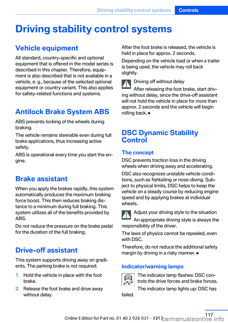
Indicator/warning lamps The indicator lamp flashes: DSC con‐
trols the drive forces and brake forces.
The indicator lamp lights up: DSC has
failed.Seite 117Driving stability control systemsControls117
Online Edition for Part no. 01 40 2 909 953 - VI/13
Page 129 of 230
System limits
Limits of ultrasonic measurement
The detection of objects can reach the physi‐
cal limits of ultrasonic measurement, e.g.:▷With tow bars and trailer hitches.▷With thin or wedge-shaped objects.▷With low objects.▷With objects with corners and sharp edges.
Low objects already displayed, e.g., curbs, can
move into the blind area of the sensors before
or after a continuous tone sounds.
High, protruding objects such as ledges may
not be detected.
False warnings
PDC may issue a warning under the following
conditions even though there is no obstacle
within the detection range:
▷In heavy rain.▷When sensors are very dirty or covered in
ice.▷When sensors are covered in snow.▷On rough road surfaces.▷In large buildings with right angles and
smooth walls, e.g., in underground ga‐
rages.▷In heavy exhaust.▷Due to other ultrasound sources, e.g.,
sweeping machines, high pressure steam
cleaners or neon lights.
Malfunction
A Check Control message is displayed.
The range of the sensors is shown as a shaded
area on the Control Display.
PDC has failed. Have the system checked.
To ensure full operability:
▷Keep the sensors clean and free of ice.▷When using high-pressure washers, do not
spray the sensors for long periods and
maintain a distance of at least 12 in/30 cm.
Surround View
The concept Surround View comprises various camera as‐
sistance systems that help the driver when
parking, maneuvering, and at complex exits
and intersections.
▷Rearview camera, refer to page 125▷Side View, refer to page 130.▷Top View, refer to page 128.
Backup camera
The concept
The backup camera provides assistance in
parking and maneuvering backwards. The area
behind the vehicle is shown on the Control
Display.
Hints Check the traffic situation as well
Check the traffic situation around the ve‐
hicle with your own eyes. Otherwise, an acci‐
dent could result from road users or objects lo‐
cated outside the picture area of the backup
camera.◀
Seite 125Driving comfortControls125
Online Edition for Part no. 01 40 2 909 953 - VI/13
Page 130 of 230
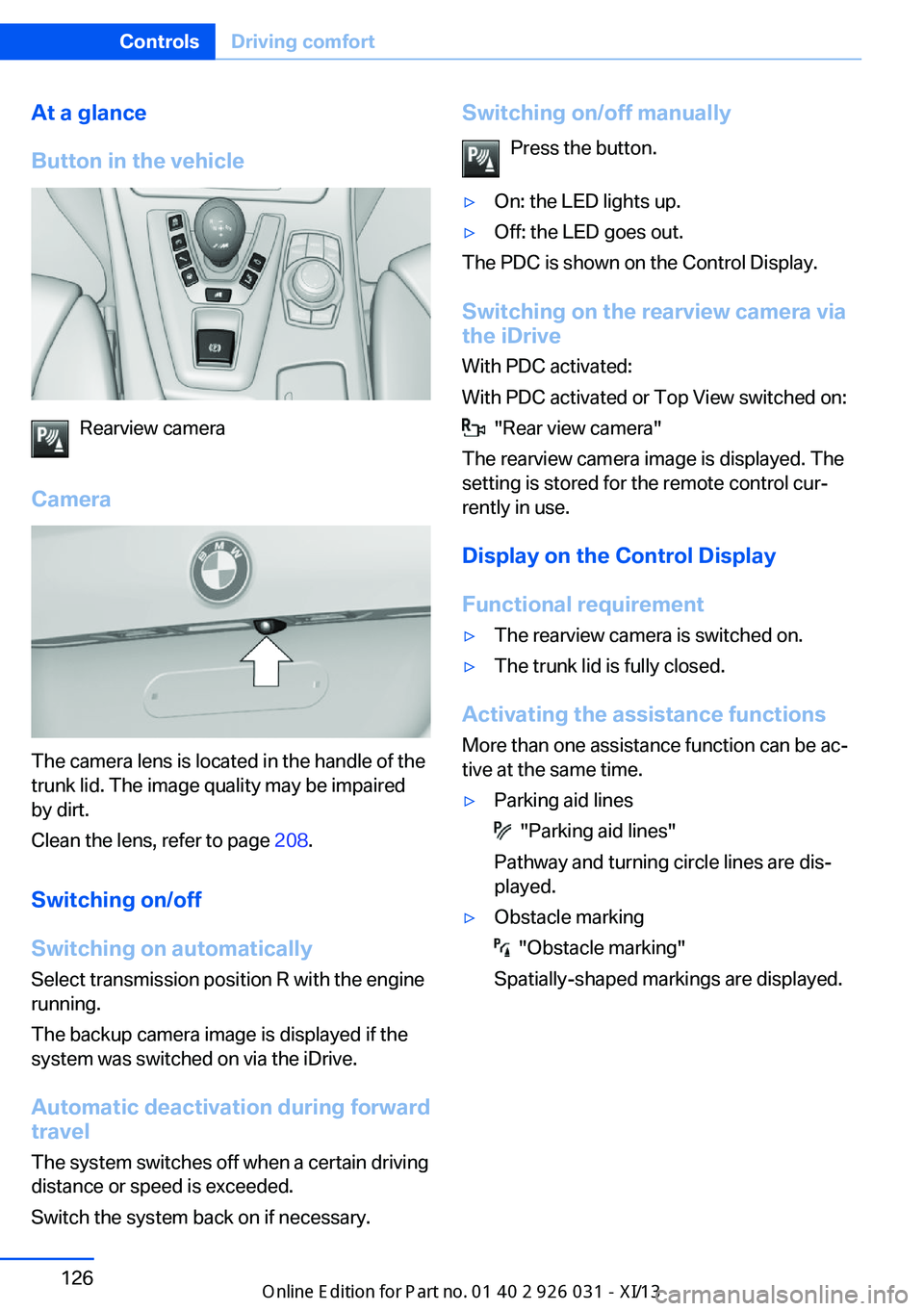
At a glance
Button in the vehicle
Rearview camera
Camera
The camera lens is located in the handle of the
trunk lid. The image quality may be impaired
by dirt.
Clean the lens, refer to page 208.
Switching on/off
Switching on automatically Select transmission position R with the engine
running.
The backup camera image is displayed if the
system was switched on via the iDrive.
Automatic deactivation during forward
travel
The system switches off when a certain driving
distance or speed is exceeded.
Switch the system back on if necessary.
Switching on/off manually
Press the button.▷On: the LED lights up.▷Off: the LED goes out.
The PDC is shown on the Control Display.
Switching on the rearview camera via
the iDrive
With PDC activated:
With PDC activated or Top View switched on:
"Rear view camera"
The rearview camera image is displayed. The
setting is stored for the remote control cur‐
rently in use.
Display on the Control Display
Functional requirement
▷The rearview camera is switched on.▷The trunk lid is fully closed.
Activating the assistance functions
More than one assistance function can be ac‐
tive at the same time.
▷Parking aid lines
"Parking aid lines"
Pathway and turning circle lines are dis‐
played.
▷Obstacle marking
"Obstacle marking"
Spatially-shaped markings are displayed.
Seite 126ControlsDriving comfort126
Online Edition for Part no. 01 40 2 909 953 - VI/13
Page 132 of 230
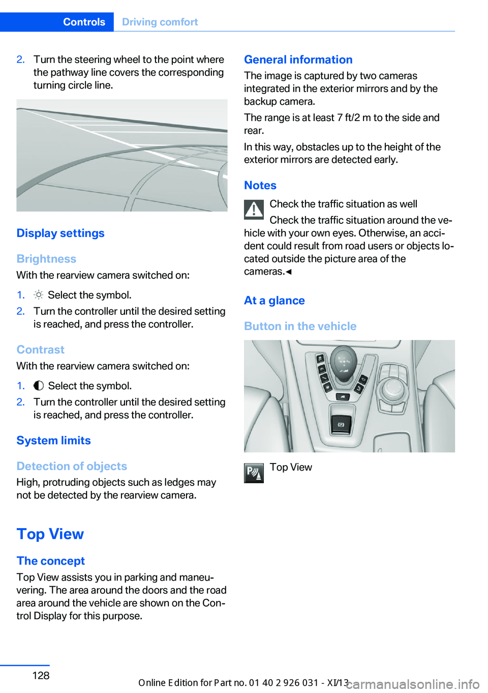
2.Turn the steering wheel to the point where
the pathway line covers the corresponding
turning circle line.
Display settings
Brightness
With the rearview camera switched on:
1. Select the symbol.2.Turn the controller until the desired setting
is reached, and press the controller.
Contrast
With the rearview camera switched on:
1. Select the symbol.2.Turn the controller until the desired setting
is reached, and press the controller.
System limits
Detection of objects
High, protruding objects such as ledges may
not be detected by the rearview camera.
Top View The concept
Top View assists you in parking and maneu‐
vering. The area around the doors and the road
area around the vehicle are shown on the Con‐
trol Display for this purpose.
General information
The image is captured by two cameras
integrated in the exterior mirrors and by the
backup camera.
The range is at least 7 ft/2 m to the side and
rear.
In this way, obstacles up to the height of the
exterior mirrors are detected early.
Notes Check the traffic situation as well
Check the traffic situation around the ve‐
hicle with your own eyes. Otherwise, an acci‐
dent could result from road users or objects lo‐
cated outside the picture area of the
cameras.◀
At a glance
Button in the vehicle
Top View
Seite 128ControlsDriving comfort128
Online Edition for Part no. 01 40 2 909 953 - VI/13
Page 134 of 230
Displaying the turning circle and
pathway lines▷The static, red turning circle line shows the
space needed to the side of the vehicle
when the steering wheel is turned all the
way.▷The variable, green pathway line assists
you in assessing the amount of space ac‐
tually needed to the side of the vehicle.
The pathway line is dependent on the cur‐
rent steering angle and is continuously ad‐
justed with the steering wheel movement.
"Parking aid lines"
Turning circle and pathway lines are displayed.
System limits
Top View cannot be used in the following sit‐
uations:
▷With a door open.▷With the trunk lid open.▷With an exterior mirror folded in.▷In poor light.
A Check Control message is displayed in some
of these situations.
Side View The concept Side View provides an early look at cross traffic
at blind driveways and intersections. Road
users concealed by obstacles to the left and
right of the vehicle can only be detected rela‐
tively late from the driver's seat. To improve
visibility, two cameras in the front of the vehi‐
cle record the traffic situation on each side.
Notes
The images from both cameras are shown si‐
multaneously on the Control Display.
Check the traffic situation as well
Check the traffic situation around the ve‐
hicle on blind driveways and intersections with
your own eyes. Otherwise, an accident could
result from road users or objects located out‐
side the picture area of the Side View cam‐
eras.◀
At a glance
Button in the vehicle
Side View
Cameras
Two cameras integrated in the bumpers cap‐
ture the image.
The two camera lenses are located on the
sides of the bumper.
The image quality may be impaired by dirt.
Clean the lens, refer to page 208.
Seite 130ControlsDriving comfort130
Online Edition for Part no. 01 40 2 909 953 - VI/13
Page 167 of 230
Do not drive in neutral
Do not drive in neutral or with the engine
stopped, as doing so disables engine braking.
In addition, steering and brake assist is un‐
available with the engine stopped.◀
Brake disc corrosion The corrosion on the brake discs and the con‐
tamination on the brake pads are furthered by:▷Low mileage.▷Extended periods when the vehicle is not
used at all.▷Infrequent use of the brakes.
Corrosion occurs when the minimum pressure
that must be exerted by the pads during brake
applications to clean the discs is not reached.
Should corrosion form on the brake discs, the
brakes will tend to respond with a pulsating ef‐
fect that generally cannot be corrected.
Condensation under the parked
vehicle
When using the automatic climate control,
condensation water develops that exits under‐
neath the vehicle.
Traces of water under the vehicle like this are
normal.
Ground clearance Limited ground clearance
Observe the limited ground clearance of
the vehicle, e. g. while entering underground
parking garages or when driving over obsta‐
cles. Otherwise, damages to the vehicle may
result.◀
To drive down from curbs with the Electronic
Damper Control, refer to page 119, select the
following program, to keep the ground clear‐
ance as even as possible: "Sport Plus"
M Driver's Package: Driving in the
higher speed range
Damage to the vehicle
To ensure problem-free driving behavior
in the maximum speed range, have any dam‐
age to the vehicle repaired as soon as possible
as it could negatively impact driving perform‐
ance. This includes, among other things, tires,
undercarriage and parts for improving aerody‐ namics.
Until the damage is repaired, do not drive the
vehicle in the higher speed range; otherwise,
there is danger of an accident.◀Seite 163Things to remember when drivingDriving tips163
Online Edition for Part no. 01 40 2 909 953 - VI/13
Page 205 of 230
Do not touch live parts
To avoid the risk of potentially fatal in‐
jury, always avoid all contact with electrical
components while the engine is running.◀
Preparation1.Check whether the battery of the other ve‐
hicle has a voltage of 12 volts. This infor‐
mation can be found on the battery.2.Switch off the engine of the assisting vehi‐
cle.3.Switch off any electronic systems/power
consumers in both vehicles.
Bodywork contact between vehicles
Make sure that there is no contact be‐
tween the bodywork of the two vehicles; other‐
wise, there is the danger of short circuits.◀
Starting aid terminals Connecting order
Connect the jumper cables in the correct
order; otherwise, there is the danger of injury
from sparking.◀
The so-called starting aid terminal in the en‐
gine compartment acts as the battery's posi‐
tive terminal.
The body ground or a special nut acts as the
battery negative terminal.
Connecting the cables
1.Pull off the cap of the BMW starting aid ter‐
minal.2.Attach one terminal clamp of the positive
jumper cable to the positive terminal of the
battery, or to the corresponding starting
aid terminal of the vehicle providing assis‐
tance.3.Attach the terminal clamp on the other end
of the cable to the positive terminal of the
battery, or to the corresponding starting
aid terminal of the vehicle to be started.4.Attach one terminal clamp of the negative
jumper cable to the negative terminal of
the battery, or to the corresponding engine
or body ground of assisting vehicle.5.Attach the second terminal clamp to the
negative terminal of the battery, or to the
corresponding engine or body ground of
the vehicle to be started.
Starting the engine
Never use spray fluids to start the engine.
1.Start the engine of the assisting vehicle
and let it run for several minutes at an in‐
creased idle speed.2.Start the engine of the vehicle being
started in the usual way.
If the first starting attempt is not success‐
ful, wait a few minutes before making an‐Seite 201Breakdown assistanceMobility201
Online Edition for Part no. 01 40 2 909 953 - VI/13