warning BMW M6 CONVERTIBLE 2010 E64 User Guide
[x] Cancel search | Manufacturer: BMW, Model Year: 2010, Model line: M6 CONVERTIBLE, Model: BMW M6 CONVERTIBLE 2010 E64Pages: 250, PDF Size: 8.4 MB
Page 68 of 250
Controls Overview
66
Engine oil temperature*
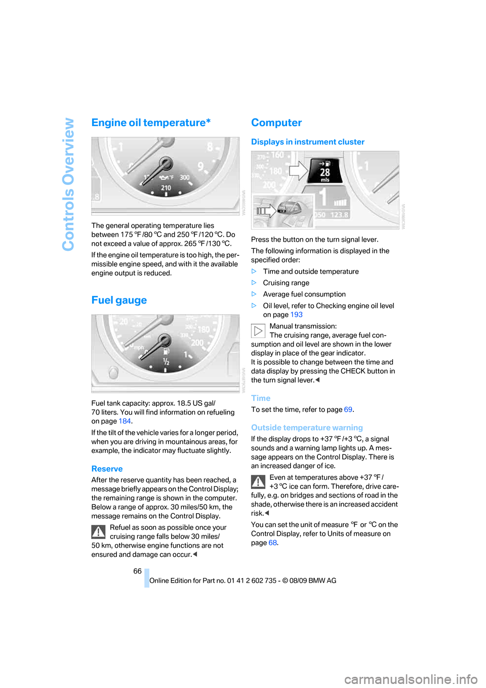
The general operating temperature lies
between 1757/806 and 2507/1206. Do
not exceed a value of approx. 2657/1306.
If the engine oil temperature is too high, the per-
missible engine speed, and with it the available
engine output is reduced.
Fuel gauge
Fuel tank capacity: approx. 18.5 US gal/
70 liters. You will find information on refueling
on page184.
If the tilt of the vehicle varies for a longer period,
when you are driving in mountainous areas, for
example, the indicator may fluctuate slightly.
Reserve
After the reserve quantity has been reached, a
message briefly appears on the Control Display;
the remaining range is shown in the computer.
Below a range of approx. 30 miles/50 km, the
message remains on the Control Display.
Refuel as soon as possible once your
cruising range falls below 30 miles/
50 km, otherwise engine functions are not
ensured and damage can occur.<
Computer
Displays in instrument cluster
Press the button on the turn signal lever.
The following information is displayed in the
specified order:
>Time and outside temperature
>Cruising range
>Average fuel consumption
>Oil level, refer to Checking engine oil level
on page193
Manual transmission:
The cruising range, average fuel con-
sumption and oil level are shown in the lower
display in place of the gear indicator.
It is possible to change between the time and
data display by pressing the CHECK button in
the turn signal lever.<
Time
To set the time, refer to page69.
Outside temperature warning
If the display drops to +377/+36, a signal
sounds and a warning lamp lights up. A mes-
sage appears on the Control Display. There is
an increased danger of ice.
Even at temperatures above +377/
+36 ice can form. Therefore, drive care-
fully, e.g. on bridges and sections of road in the
shade, otherwise there is an increased accident
risk.<
You can set the unit of measure 7 or 6 on the
Control Display, refer to Units of measure on
page68.
Page 73 of 250
Controls
71Reference
At a glance
Driving tips
Communications
Navigation
Entertainment
Mobility
and warning lamps in the instrument cluster,
and if necessary an acoustic signal and text
messages at the bottom of the Control Display.
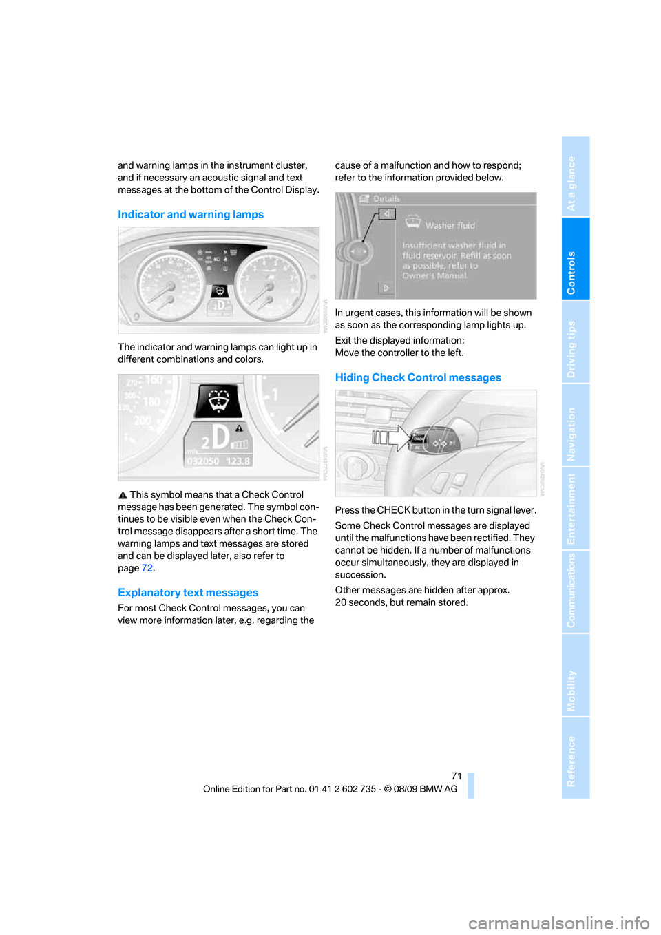
Indicator and warning lamps
The indicator and warning lamps can light up in
different combinations and colors.
This symbol means that a Check Control
message has been generated. The symbol con-
tinues to be visible even when the Check Con-
trol message disappears after a short time. The
warning lamps and text messages are stored
and can be displayed later, also refer to
page72.
Explanatory text messages
For most Check Control messages, you can
view more information later, e.g. regarding the cause of a malfunction and how to respond;
refer to the information provided below.
In urgent cases, this information will be shown
as soon as the corresponding lamp lights up.
Exit the displayed information:
Move the controller to the left.
Hiding Check Control messages
Press the CHECK button in the turn signal lever.
Some Check Control messages are displayed
until the malfunctions have been rectified. They
cannot be hidden. If a number of malfunctions
occur simultaneously, they are displayed in
succession.
Other messages are hidden after approx.
20 seconds, but remain stored.
Page 74 of 250
Controls Overview
72
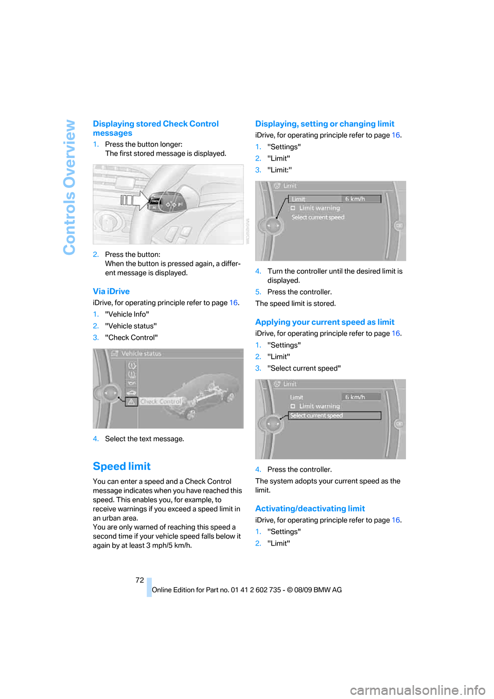
Displaying stored Check Control
messages
1.Press the button longer:
The first stored message is displayed.
2.Press the button:
When the button is pressed again, a differ-
ent message is displayed.
Via iDrive
iDrive, for operating principle refer to page16.
1."Vehicle Info"
2."Vehicle status"
3."Check Control"
4.Select the text message.
Speed limit
You can enter a speed and a Check Control
message indicates when you have reached this
speed. This enables you, for example, to
receive warnings if you exceed a speed limit in
an urban area.
You are only warned of reaching this speed a
second time if your vehicle speed falls below it
again by at least 3 mph/5 km/h.
Displaying, setting or changing limit
iDrive, for operating principle refer to page16.
1."Settings"
2."Limit"
3."Limit:"
4.Turn the controller until the desired limit is
displayed.
5.Press the controller.
The speed limit is stored.
Applying your current speed as limit
iDrive, for operating principle refer to page16.
1."Settings"
2."Limit"
3."Select current speed"
4.Press the controller.
The system adopts your current speed as the
limit.
Activating/deactivating limit
iDrive, for operating principle refer to page16.
1."Settings"
2."Limit"
Page 75 of 250
Controls
73Reference
At a glance
Driving tips
Communications
Navigation
Entertainment
Mobility
3."Limit warning"
4.Press the controller.
The limit warning is switched on.
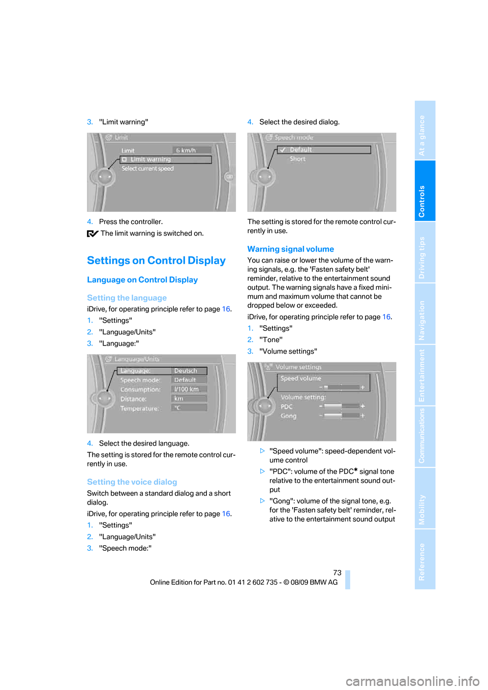
Settings on Control Display
Language on Control Display
Setting the language
iDrive, for operating principle refer to page16.
1."Settings"
2."Language/Units"
3."Language:"
4.Select the desired language.
The setting is stored for the remote control cur-
rently in use.
Setting the voice dialog
Switch between a standard dialog and a short
dialog.
iDrive, for operating principle refer to page16.
1."Settings"
2."Language/Units"
3."Speech mode:"4.Select the desired dialog.
The setting is stored for the remote control cur-
rently in use.
Warning signal volume
You can raise or lower the volume of the warn-
ing signals, e.g. the 'Fasten safety belt'
reminder, relative to the entertainment sound
output. The warning signals have a fixed mini-
mum and maximum volume that cannot be
dropped below or exceeded.
iDrive, for operating principle refer to page16.
1."Settings"
2."Tone"
3."Volume settings"
>"Speed volume": speed-dependent vol-
ume control
>"PDC": volume of the PDC
* signal tone
relative to the entertainment sound out-
put
>"Gong": volume of the signal tone, e.g.
for the 'Fasten safety belt' reminder, rel-
ative to the entertainment sound output
Page 77 of 250
Controls
75Reference
At a glance
Driving tips
Communications
Navigation
Entertainment
Mobility
Technology for comfort, convenience and
safety
PDC Park Distance Control*
The concept
The PDC assists you when you are parking.
Acoustic signals and an optical display
* alert
you to the approach of an object from behind
your vehicle. To measure the distance, there
are four ultrasonic sensors in each bumper.
The range of these sensors is approx. 7 ft/2 m.
However, an acoustic warning first sounds for
the sensors at the front and at the two rear cor-
ners at approx. 24 in/60 cm, and for the center
rear sensors at approx. 5 ft/1.50 m.
PDC is a parking aid that can indicate
objects when they are approached
slowly, as is usually the case when parking.
Avoid approaching an object at high speed, oth-
erwise the physical circumstances would mean
that the system warning was too late.<
Switching on automatically
The system starts to operate approx. one sec-
ond after you shift into reverse or move the
selector lever into position R with the engine
running or the ignition switched on.
Wait this short time before driving off.
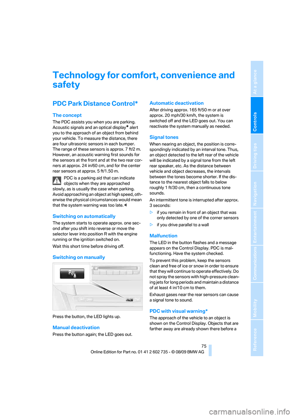
Switching on manually
Press the button, the LED lights up.
Manual deactivation
Press the button again; the LED goes out.
Automatic deactivation
After driving approx. 165 ft/50 m or at over
approx. 20 mph/30 km/h, the system is
switched off and the LED goes out. You can
reactivate the system manually as needed.
Signal tones
When nearing an object, the position is corre-
spondingly indicated by an interval tone. Thus,
an object detected to the left rear of the vehicle
will be indicated by a signal tone from the left
rear speaker, etc. As the distance between
vehicle and object decreases, the intervals
between the tones become shorter. If the dis-
tance to the nearest object falls to below
roughly 1 ft/30 cm, then a continuous tone
sounds.
An intermittent tone is interrupted after approx.
3seconds:
>if you remain in front of an object that was
only detected by one of the corner sensors
>if you drive parallel to a wall
Malfunction
The LED in the button flashes and a message
appears on the Control Display. PDC is mal-
functioning. Have the system checked.
To prevent this problem, keep the sensors
clean and free of ice or snow in order to ensure
that they will continue to operate effectively. Do
not spray the sensors with high-pressure clean-
ing jets for long periods and maintain a distance
of at least 4 in/10 cm to them.
Exhaust gases near the rear sensors can cause
a signal tone to sound.
PDC with visual warning*
The approach of the vehicle to an object is
shown on the Control Display. Objects that are
farther away are already shown there before a
Page 80 of 250
Technology for comfort, convenience and safety
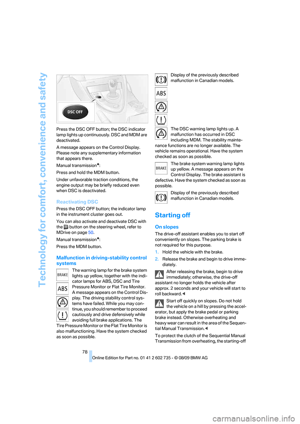
78 Press the DSC OFF button; the DSC indicator
lamp lights up continuously. DSC and MDM are
deactivated.
A message appears on the Control Display.
Please note any supplementary information
that appears there.
Manual transmission
*:
Press and hold the MDM button.
Under unfavorable traction conditions, the
engine output may be briefly reduced even
when DSC is deactivated.
Reactivating DSC
Press the DSC OFF button; the indicator lamp
in the instrument cluster goes out.
You can also activate and deactivate DSC with
the button on the steering wheel, refer to
MDrive on page50.
Manual transmission
*:
Press the MDM button.
Malfunction in driving-stability control
systems
The warning lamp for the brake system
lights up yellow, together with the indi-
cator lamps for ABS, DSC and Tire
Pressure Monitor or Flat Tire Monitor.
A message appears on the Control Dis-
play. The driving stability control sys-
tems have failed. While you may con-
tinue, you should remember to proceed
cautiously and drive defensively while
avoiding full brake applications. The
Tire Pressure Monitor or the Flat Tire Monitor is
also malfunctioning. Have the system checked
as soon as possible.Display of the previously described
malfunction in Canadian models.
The DSC warning lamp lights up. A
malfunction has occurred in DSC
including MDM. The stability mainte-
nance functions are no longer available. The
vehicle remains operational. Have the system
checked as soon as possible.
The brake system warning lamp lights
up yellow. A message appears on the
Control Display. The brake assistant is
defective. Have the system checked as soon as
possible.
Display of the previously described
malfunction in Canadian models.
Starting off
On slopes
The drive-off assistant enables you to start off
conveniently on slopes. The parking brake is
not required for this purpose.
1.Hold the vehicle with the brake.
2.Release the brake and begin to drive imme-
diately.
After releasing the brake, begin to drive
immediately; otherwise, the drive-off
assistant no longer holds the vehicle after
approx. 2 seconds and your vehicle will start to
roll backward.<
Start off quickly on slopes. Do not hold
the vehicle on a hill by pressing the accel-
erator, but apply the brake pedal or parking
brake instead. Otherwise overheating and
heavy wear can result in the area of the Sequen-
tial Manual Transmission.<
To protect the clutch of the Sequential Manual
Transmission from overheating, the starting-off
Page 82 of 250
Technology for comfort, convenience and safety
80 In the event of a pressure loss, there is a change
in the rolling circumference and therefore the
rotation speed of the corresponding wheel. The
system detects this change and reports it as a
flat tire.
Functional requirement
The system must have been initialized when the
tire inflation pressure was correct; otherwise,
reliable signaling of a flat tire is not ensured.
The initialization must be repeated after
every correction of the tire inflation pres-
sure and after every tire or wheel change.<
System limits
The Flat Tire Monitor is unable to warn
the driver of sudden, severe tire damage
caused by external factors, nor can it identify
the gradual loss of pressure that will inevitably
occur in all four tires over a lengthy period of
time.<
In the following situations, the system could be
delayed or malfunction:
>System has not been initialized
>Driving on snowy or slippery road surface
>Sporty driving style: slip in the drive wheels,
high lateral acceleration
>Driving with snow chains
*
Initializing system
The initialization finishes during driving,
which can be interrupted at any time.
When driving resumes, the initialization is con-
tinued automatically. The system is initialized
after this activation phase.
The initialization process adopts the set infla-
tion tire pressures as reference values for the
detection of a flat tire. Initialization is started by
confirming the inflation pressures.
The system is not initialized when traveling with
snow chains
*.<
With Sequential Manual Transmission via the
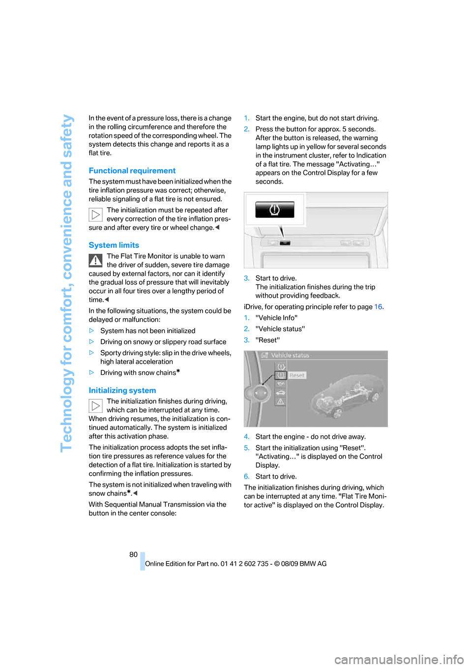
button in the center console:1.Start the engine, but do not start driving.
2.Press the button for approx. 5 seconds.
After the button is released, the warning
lamp lights up in yellow for several seconds
in the instrument cluster, refer to Indication
of a flat tire. The message "Activating…"
appears on the Control Display for a few
seconds.
3.Start to drive.
The initialization finishes during the trip
without providing feedback.
iDrive, for operating principle refer to page16.
1."Vehicle Info"
2."Vehicle status"
3."Reset"
4.Start the engine - do not drive away.
5.Start the initialization using "Reset".
"Activating…" is displayed on the Control
Display.
6.Start to drive.
The initialization finishes during driving, which
can be interrupted at any time. "Flat Tire Moni-
tor active" is displayed on the Control Display.
Page 83 of 250
Controls
81Reference
At a glance
Driving tips
Communications
Navigation
Entertainment
Mobility
Indication of a flat tire
The warning lamp lights up red. A mes-
sage appears on the Control Display.
In addition, an acoustic signal sounds.
There is a flat tire or extensive inflation pressure
loss.
1.Reduce speed and stop the vehicle care-
fully. Avoid sudden braking and steering
maneuvers.
2.Identify damaged tire. To do this, check the
tire inflation pressure using the M Mobility
System, refer to Producing tire inflation
pressure on page207.
3.Repair the flat tire with the M Mobility Sys-
tem, refer to page205, or replace the dam-
aged wheel, refer to Changing wheels on
page207.
TPM Tire Pressure Monitor*
The concept
TPM checks the tire inflation pressure in the
four mounted tires. The system reports when
the tire inflation pressure has dropped consid-
erably in one or several tires.
Functional requirement
In order to assure the reliable reporting of a flat
tire, the system must have been reset with the
correct tire inflation pressure.
Always use wheels with TPM electronics, oth-
erwise fault-free operation of the system is not
ensured.
Reset the system again after each correc-
tion of the tire inflation pressure and after
every tire or wheel change.<
System limits
TPM cannot announce sudden serious
tire damage caused by external influ-
ences.<
The system does not function properly if it has
not been reset, e.g. a flat tire is reported despite
correct tire inflation pressures.The system is inactive and cannot display a flat
tire if a wheel has been mounted without TPM
electronics, or if TPM is temporarily interfered
with by other systems or devices which use the
same radio frequency.
Status display on Control Display
The tire and system status is indicated by the
color of the tires.
TPM takes the fact that the tire pressure
changes during driving into account. A correc-
tion is only required if requested by TPM with
the color.
Green
The tire pressure matches the learned set state.
"TPM" appears on the Control Display.
One wheel is yellow
Flat tire or a major drop in inflation pressure in
the indicated tire. A message appears on the
Control Display.
All wheels are yellow
Flat tire or a major drop in inflation pressure in
several tires. A message appears on the Control
Display.
Gray
The system cannot detect a flat tire.
Reasons for this can be:
>TPM is being reset
>Temporary interference due to systems or
devices which use the same radio fre-
quency
>Malfunction
Resetting system
Reset the system again after each correc-
tion of the tire inflation pressure and after
every tire or wheel change.<
Resetting finishes during driving, which can be
interrupted at any time. When driving resumes,
resetting is continued automatically.
iDrive, for operating principle refer to page16.
Page 84 of 250
Technology for comfort, convenience and safety
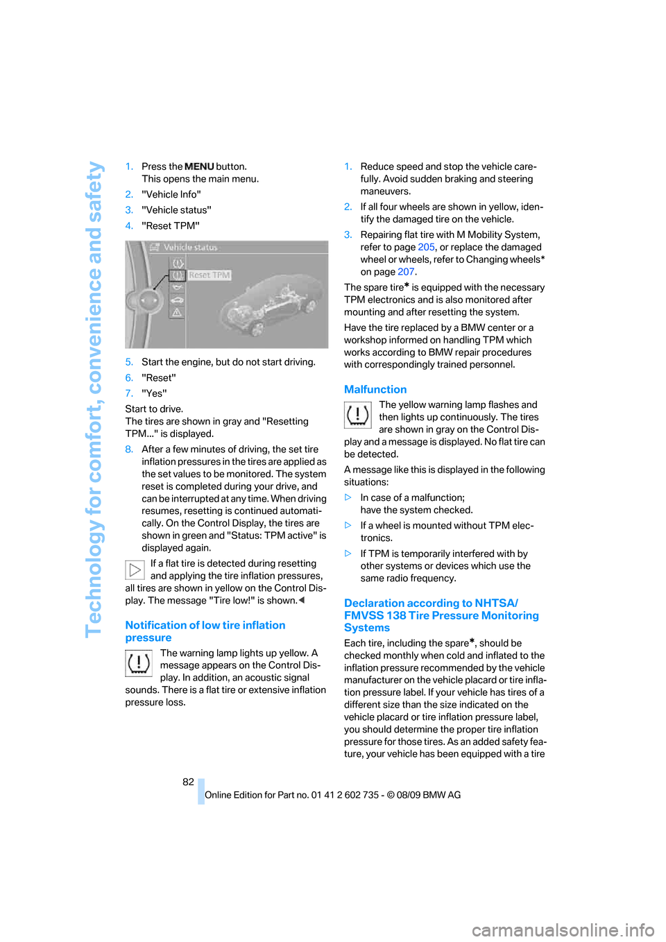
82 1.Press the button.
This opens the main menu.
2."Vehicle Info"
3."Vehicle status"
4."Reset TPM"
5.Start the engine, but do not start driving.
6."Reset"
7."Yes"
Start to drive.
The tires are shown in gray and "Resetting
TPM..." is displayed.
8.After a few minutes of driving, the set tire
inflation pressures in the tires are applied as
the set values to be monitored. The system
reset is completed during your drive, and
can be interrupted at any time. When driving
resumes, resetting is continued automati-
cally. On the Control Display, the tires are
shown in green and "Status: TPM active" is
displayed again.
If a flat tire is detected during resetting
and applying the tire inflation pressures,
all tires are shown in yellow on the Control Dis-
play. The message "Tire low!" is shown.<
Notification of low tire inflation
pressure
The warning lamp lights up yellow. A
message appears on the Control Dis-
play. In addition, an acoustic signal
sounds. There is a flat tire or extensive inflation
pressure loss.1.Reduce speed and stop the vehicle care-
fully. Avoid sudden braking and steering
maneuvers.
2.If all four wheels are shown in yellow, iden-
tify the damaged tire on the vehicle.
3.Repairing flat tire with M Mobility System,
refer to page205, or replace the damaged
wheel or wheels, refer to Changing wheels*
on page207.
The spare tire
* is equipped with the necessary
TPM electronics and is also monitored after
mounting and after resetting the system.
Have the tire replaced by a BMW center or a
workshop informed on handling TPM which
works according to BMW repair procedures
with correspondingly trained personnel.
Malfunction
The yellow warning lamp flashes and
then lights up continuously. The tires
are shown in gray on the Control Dis-
play and a message is displayed. No flat tire can
be detected.
A message like this is displayed in the following
situations:
>In case of a malfunction;
have the system checked.
>If a wheel is mounted without TPM elec-
tronics.
>If TPM is temporarily interfered with by
other systems or devices which use the
same radio frequency.
Declaration according to NHTSA/
FMVSS 138 Tire Pressure Monitoring
Systems
Each tire, including the spare*, should be
checked monthly when cold and inflated to the
inflation pressure recommended by the vehicle
manufacturer on the vehicle placard or tire infla-
tion pressure label. If your vehicle has tires of a
different size than the size indicated on the
vehicle placard or tire inflation pressure label,
you should determine the proper tire inflation
pressure for those tires. As an added safety fea-
ture, your vehicle has been equipped with a tire
Page 86 of 250
Technology for comfort, convenience and safety
84 head and side airbags help provide protection in
the event of side impact. The relevant side air-
bag supports the side upper body area. The
head air bag supports the head. The knee air-
bag protects the legs from colliding with the
cockpit.
The airbags are deliberately not triggered in
every impact situation, e. g. less severe acci-
dents or rear-end collisions.
Do not apply adhesive materials to the
cover panels of the airbags, cover them or
modify them in any other way. Do not attempt to
remove the airbag restraint system from the
vehicle. Do not modify or tamper with either the
wiring or the individual components in the air-
bag system. This category includes the uphol-
stery in the center of the steering wheel, on the
instrument panel, the side trim panels on the
doors and on the Coupe, the roof pillars along
with the sides of the headliner. Do not attempt
to remove or dismantle the steering wheel.
Do not touch the individual components
directly after the system has been triggered,
because there is a danger of burns.
In the event of malfunctions, deactivation, or
triggering of the airbag restraint system, have
the testing, repair, removal, and disposal of air-
bag generators executed only by a BMW center
or a workshop that works according to BMW
repair procedures with correspondingly trained
personnel and has the required explosives
licenses. Otherwise unprofessional attempts to
service the system could lead to failure in an
emergency or undesired airbag triggering,
either of which could result in personal injury.<
Warnings and information on the airbags is also
provided on the sun visors.
Automatic deactivation of front
passenger airbags
The occupation of the seat is detected by eval-
uating the impression on the occupied seat sur-
face of the front passenger seat. The system
correspondingly activates or deactivates the
front, knee and side airbags on the front pas-
senger side.The current status of the front passenger
airbag, i.e. deactivated or activated, is
indicated by the indicator lamp over the interior
rearview mirror, refer to Operating state of front
passenger airbags in the following.<
Before transporting a child in the front
passenger seat, read the safety informa-
tion and follow the instructions under Trans-
porting children safely, refer to page52.
The front, knee and side airbags on the front
passenger side can be deactivated for teenag-
ers and adults in certain sitting positions; the
indicator lamp for the front passenger airbags
lights up when this occurs. In these cases,
change the sitting position so that the front pas-
senger airbags are activated and the indicator
lamp goes out. If the desired status cannot be
produced by changing the sitting position,
transport the corresponding person in the rear
seat.
Do not fit seat covers, seat cushion padding,
ball mats or other items onto the front passen-
ger seat unless they are specifically recom-
mended by BMW. Do not lay objects under the
seat which could press against the seat from
below. Otherwise a correct evaluation of the
occupied seat surface cannot be ensured.<
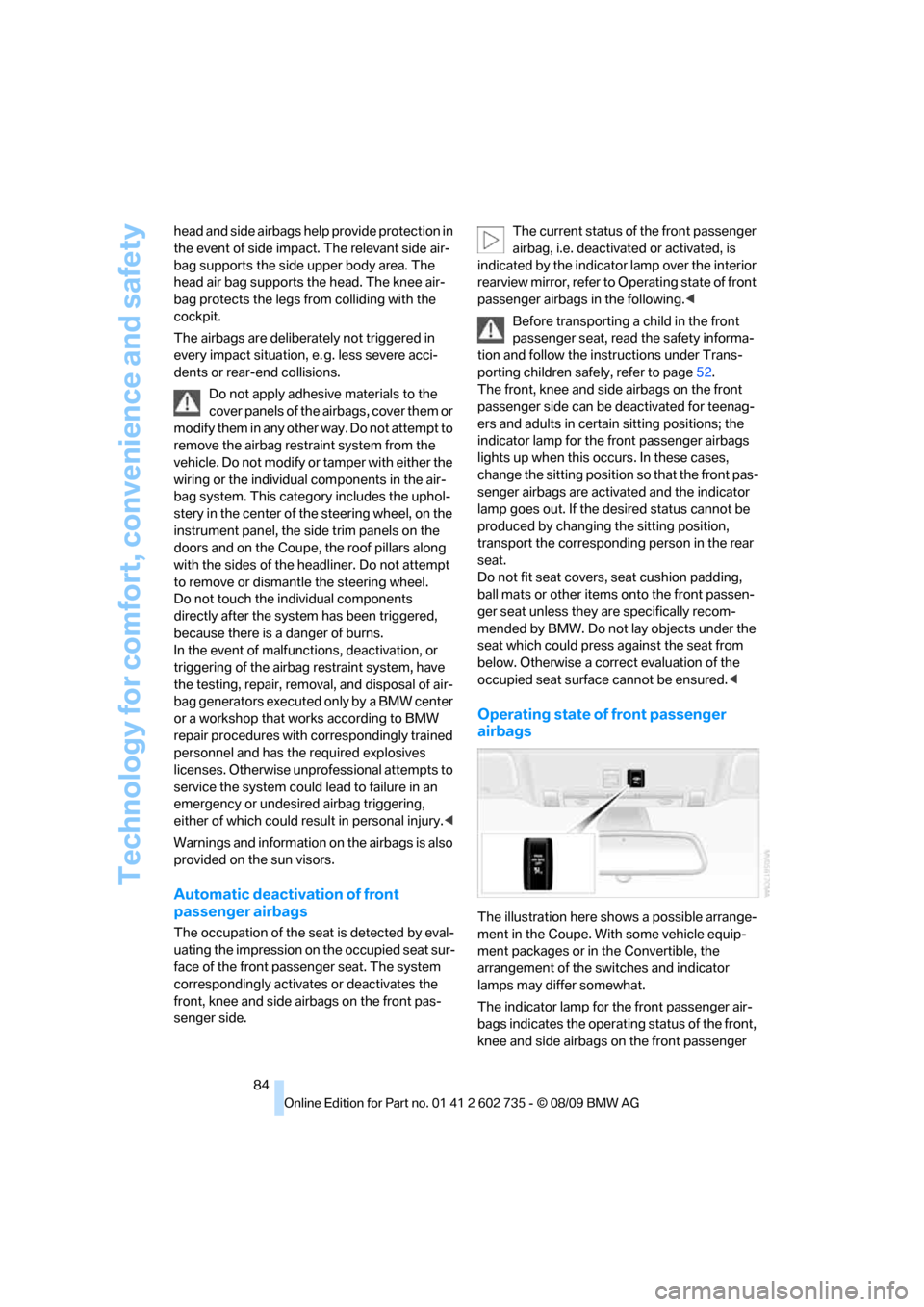
Operating state of front passenger
airbags
The illustration here shows a possible arrange-
ment in the Coupe. With some vehicle equip-
ment packages or in the Convertible, the
arrangement of the switches and indicator
lamps may differ somewhat.
The indicator lamp for the front passenger air-
bags indicates the operating status of the front,
knee and side airbags on the front passenger