radio controls BMW M6 CONVERTIBLE 2012 Owners Manual
[x] Cancel search | Manufacturer: BMW, Model Year: 2012, Model line: M6 CONVERTIBLE, Model: BMW M6 CONVERTIBLE 2012Pages: 297, PDF Size: 12.09 MB
Page 5 of 297
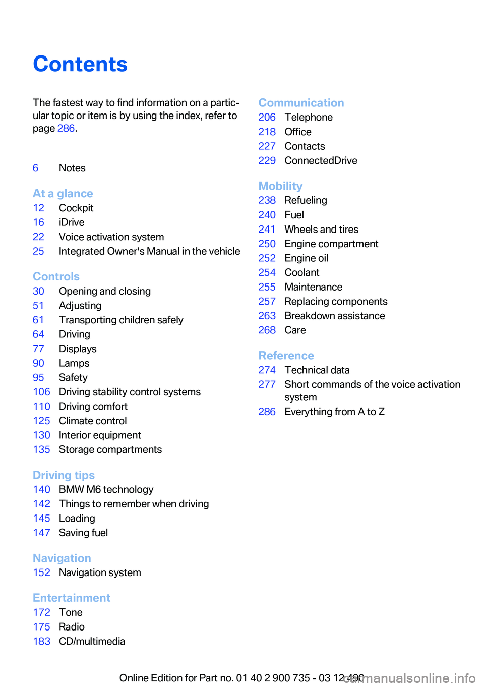
ContentsThe fastest way to find information on a partic‐
ular topic or item is by using the index, refer to
page 286.6Notes
At a glance
12Cockpit16iDrive22Voice activation system25Integrated Owner's Manual in the vehicle
Controls
30Opening and closing51Adjusting61Transporting children safely64Driving77Displays90Lamps95Safety106Driving stability control systems110Driving comfort125Climate control130Interior equipment135Storage compartments
Driving tips
140BMW M6 technology142Things to remember when driving145Loading147Saving fuel
Navigation
152Navigation system
Entertainment
172Tone175Radio183CD/multimediaCommunication206Telephone218Office227Contacts229ConnectedDrive
Mobility
238Refueling240Fuel241Wheels and tires250Engine compartment252Engine oil254Coolant255Maintenance257Replacing components263Breakdown assistance268Care
Reference
274Technical data277Short commands of the voice activation
system286Everything from A to Z
Online Edition for Part no. 01 40 2 900 735 - 03 12 490
Page 31 of 297
4.Insert a battery of the same type with the
positive side facing upwards.5.Press the cover closed.
Take the used battery to a recycling cen‐
ter or to your service center.
New remote controls
You can obtain new remote controls from your
service center.
Loss of the remote controls
Lost remote controls can be blocked by your
service center.
Emergency detection of remote control
It is possible to switch on the ignition or start the
engine in situations such as the following:
▷Interference of radio transmission to remote
control by external sources.▷Discharged battery in the remote control.▷Interference of radio transmission by mobile
devices in close proximity to the remote
control.▷Interference of radio transmission by
charger while charging items such as mobile
devices in the vehicle.
A Check Control message is displayed if an at‐
tempt is made to switch on the ignition or start
the engine.
Starting the engine in case of
emergency detection of remote control
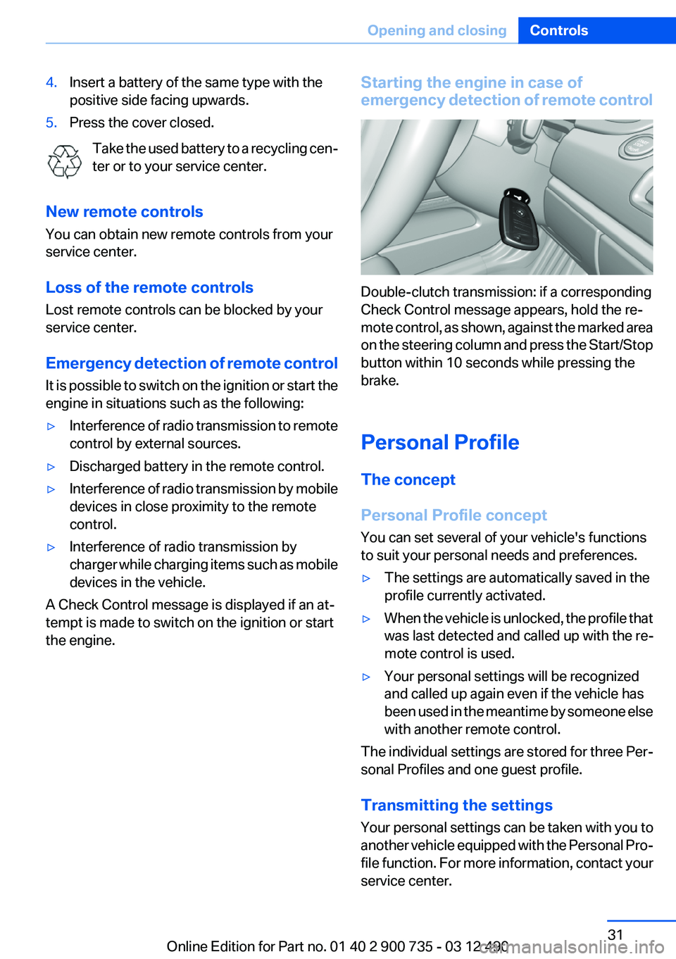
Double-clutch transmission: if a corresponding
Check Control message appears, hold the re‐
mote control, as shown, against the marked area
on the steering column and press the Start/Stop
button within 10 seconds while pressing the
brake.
Personal Profile
The concept
Personal Profile concept
You can set several of your vehicle's functions
to suit your personal needs and preferences.
▷The settings are automatically saved in the
profile currently activated.▷When the vehicle is unlocked, the profile that
was last detected and called up with the re‐
mote control is used.▷Your personal settings will be recognized
and called up again even if the vehicle has
been used in the meantime by someone else
with another remote control.
The individual settings are stored for three Per‐
sonal Profiles and one guest profile.
Transmitting the settings
Your personal settings can be taken with you to
another vehicle equipped with the Personal Pro‐
file function. For more information, contact your
service center.
Seite 31Opening and closingControls31
Online Edition for Part no. 01 40 2 900 735 - 03 12 490
Page 33 of 297
Using the guest profile
The guest profile can be used to make individual
settings without affecting the three Personal
Profiles.
This can be useful for drivers who are using the
vehicle temporarily and do not have their own
profile.1."Settings"2."Profiles"3.The current profile is selected.4.Open "Guest".5.Create the settings.
Note: the guest profile cannot be renamed.
Display profile list during start
The profile list can be displayed during each
start for selecting the desired profile.
1."Settings"2."Profiles"3."Options" Open.4."Display user list at startup"
Personal Profile settings
The following functions and settings can be
stored in a profile.
More information on the settings can be found
under:
▷Exterior mirror position.▷CD/Multimedia: audio source listened to
last.▷Driver's seat position: automatic retrieval af‐
ter unlocking.▷Programmable memory buttons: assign‐
ment.▷Head-up Display: selection, brightness, po‐
sition and rotation of the display.▷Headlamp courtesy delay feature: time set‐
ting.▷Tone: tone settings.▷Automatic climate control: settings.▷Steering wheel position.▷M Drive: configurations.▷Navigation: map views, route criteria, voice
output on/off.▷Night Vision with pedestrian detection: se‐
lection of functions and type of display.▷Park Distance Control PDC: adjusting the
signal tone volume.▷Radio: stored stations, station listened to
last, special settings.▷Backup camera: selection of functions and
type of display.▷Side View: selection of the display type.▷Language on the Control Display.▷Lane departure warning: last setting, on/off.▷Active Blind Spot Detection: last setting, on/
off.▷Daytime running lights: current setting.▷Triple turn signal activation.▷Locking the vehicle: after a brief period or
after starting to drive.
Central locking system
The concept
The central locking system becomes active
when the driver's door is closed.
The system simultaneously engages and re‐
leases the locks on the following:
▷Doors.▷Compartment in the center armrest.▷Trunk lid.▷Fuel filler flap.
Operating from the outside
▷Via the remote control.▷Via the driver's door lock.▷Via the door handles.Seite 33Opening and closingControls33
Online Edition for Part no. 01 40 2 900 735 - 03 12 490
Page 44 of 297
Convertible top
General information
The convertible top can be opened or closed at
speeds up to approx. 25 mph/40 km/h.
If the vehicle is accelerated above a speed of
approx. 30 mph/50 km/h while the convertible
top is being moved, the convertible top move‐
ment stops.
Tips about the convertible top:▷If possible, close the convertible top when
the vehicle is parked. A closed convertible
top protects it from weather-related dam‐
age and to some extent from theft.▷Event when the convertible top is closed,
only store valuables in the locked cargo area.▷At higher speeds, vacuum produced in the
passenger compartment cause the
convertible top to begin to flatten. Increase
the amount of air via the automatic climate
control so that no vacuum is produced in the
vehicle.
Notes
The trunk lid cannot be opened if the convertible
top is not fully opened or closed.
Safety information about the convertible
top
▷With temperatures below +14 ℉/-10 ℃ do
not open the convertible top; otherwise
damages could result.▷Do not leave the open convertible top in the
convertible top well longer than one day
while the top is still wet; otherwise, damage
could result due to moisture.▷The convertible top pivots up during open‐
ing and closing. When the top is moved, e.g.
in garages, make sure that there is a mini‐
mum height of 79 inches/2 meters; other‐
wise, it damages may result.▷Do not place any objects on the convertible
top, otherwise, they could fall and cause
damage or injuries.▷When the rollover protection system is ex‐
tended, do not under any circumstances
move the convertible top.▷Always open or close the convertible top
completely. Convertible top and convertible
top well storage cover are locked in the final
positions. Driving with the convertible tope
or convertible top well storage cover un‐
locked can result in damage.▷Do not reach into the convertible top mech‐
anism during the opening and closing oper‐
ation. Keep children away from the opening
path of the convertible top, otherwise, there
is a risk of injury.▷When the convertible top is opened during
driving, be alert to traffic; otherwise, it may
result in an accident. If possible, do not move
the convertible top while driving in reverse
because rearward vision is severely im‐
paired while the convertible top is in motion.
During windy conditions, do not operate the
convertible top while driving. Do not drive
faster than 30 mph/50 km/h; otherwise, ve‐
hicle damage may occur.▷Do not attach any roof carrier systems; oth‐
erwise, an accident may occur.◀
Functional requirements
The ignition or radio ready state must be
switched on.
It is not possible to start the engine and operate
the convertible top simultaneously. When the
engine is started, the convertible top movement
is briefly interrupted.
Under the following conditions, the convertible
top movement cannot be moved and a Check
Control message is displayed.
▷Cargo area partition is flipped up.▷Trunk lid is open.▷External temperature is too low.Seite 44ControlsOpening and closing44
Online Edition for Part no. 01 40 2 900 735 - 03 12 490
Page 64 of 297
DrivingVehicle equipment
All standard, country-specific and optional
equipment that is offered in the model series is
described in this chapter. Therefore, equipment
is also described that is not available in a vehicle,
e. g., because of the selected optional equip‐
ment or country variant. This also applies for
safety-related functions and systems.
Start/Stop button
The concept Pressing the Start/Stop button
switches the ignition on or off and
starts the engine.
Double clutch transmission: The
engine starts if the brake is de‐
pressed while pressing the Start/Stop button.
Ignition on
Double-clutch transmission: Press the Start/
Stop button but do not depress the brake.
All vehicle systems are ready for operation.
Most of the indicator and warning lamps in the
instrument cluster light up for varying lengths of
time.
To save battery power when the engine is off,
switch off the ignition and any unnecessary
electronic systems/power consumers.
The ignition switches off automatically:▷When the vehicle is locked, if the low beams
are switched on.▷Shortly before the battery is discharged
completely, so that the engine can still be
started.▷If the engine is switched off and the ignition
is switched on, the system automatically
switches to the radio ready state when thedoor is opened if the lights are switched off
or the daytime running lights are switched
on.
Ignition off
Double-clutch transmission: Press the Start/
Stop button again, but do not depress the brake.
All indicator lamps in the instrument cluster go
out.
To save battery power when the engine is off,
switch off the ignition and any unnecessary
electronic systems/power consumers.
Transmission position P with the ignition
off
When the ignition is switched off, position P is
engaged automatically. When in an automatic
car wash, for example, ensure that the ignition is
not switched off accidentally.◀
Ignition automatically cuts off while the vehicle
is stationary and the engine is stopped:
▷During locking, also with the low beams ac‐
tivated.▷Shortly before the battery is discharged
completely, so that the engine can still be
started. This function is only available when
the low beams are switched off.▷When opening and closing the driver door, if
the driver's seat belt is unbuckled and the
low beams are switched off.▷While the driver's seat belt is unbuckled, if
the driver's door is open and the low beams
are switched off.
When the ignition is switched off, by opening or
closing the driver's door or unbuckling the driv‐
er's seat belt, the radio ready state remains ac‐
tive.
Radio ready state
Activate radio ready state:
Seite 64ControlsDriving64
Online Edition for Part no. 01 40 2 900 735 - 03 12 490
Page 65 of 297
▷When the ignition is switched off: press ON/
OFF button on the radio.▷When the engine is running: press the Start/
Stop button.
Some electronic systems/power consumers re‐
main ready for operation.
Radio ready state switches off automatically:
▷After approx. 8 minutes.▷When the vehicle is locked using the central
locking system.▷Shortly before the battery is discharged
completely, so that the engine can still be
started.
Starting the engine
Double-clutch transmission
Starting the engine
1.Depress the brake pedal.2.Press the Start/Stop button.
The ignition is activated automatically for a cer‐
tain time and is stopped as soon as the engine
starts.
Engine stop
General information Take the remote control with you
Take the remote control with you when
leaving the vehicle so that children, for example,
cannot start the engine.◀
Set the parking brake and further secure
the vehicle as required
Set the parking brake firmly when parking; oth‐
erwise, the vehicle could roll. On steep upward
and downward inclines, further secure the vehi‐
cle, for example, by turning the steering wheel in
the direction of the curb. ◀
Before driving into a car wash
In order for the vehicle to be able to roll into a car
wash, heed the information regarding Washing
in automatic car washes, refer to page 268.
Double-clutch transmission
Switching off the engine1.Apply the brakes until the vehicle comes to
a stop.2.Press the Start/Stop button.
The engine is switched off.
The radio ready state is switched on.3.Set the parking brake.
Auto Start/Stop function
The concept
The Auto Start/Stop function helps save fuel.
The system switches off the engine during a
stop, e.g., in a traffic congestion or at traffic
lights. The ignition remains switched on. The
engine starts again automatically for driving off.
Certain vehicle components may experience
additional wear as a result of this system.
Semi-automatic mode
After every start of the engine, the Auto Start
Stop function is in the last selected state, refer
to page 67. If the Auto Start Stop function is
activated, it will be available after a given speed
is exceeded:
▷Double-clutch transmission: from 5 mph,
approx. 9 km/h.
Engine stop
The engine is switched off automatically during
a stop under the following conditions:
Double-clutch transmission:
▷The selector lever is in transmission position
D.Seite 65DrivingControls65
Online Edition for Part no. 01 40 2 900 735 - 03 12 490
Page 78 of 297
Electronic displays
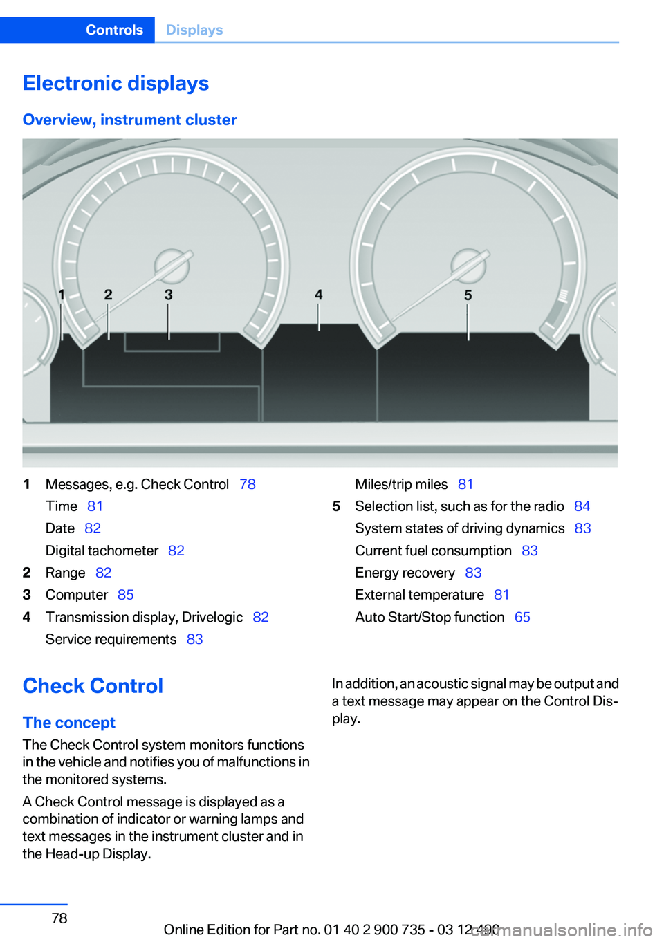
Overview, instrument cluster1Messages, e.g. Check Control 78
Time 81
Date 82
Digital tachometer 822Range 823Computer 854Transmission display, Drivelogic 82
Service requirements 83Miles/trip miles 815Selection list, such as for the radio 84
System states of driving dynamics 83
Current fuel consumption 83
Energy recovery 83
External temperature 81
Auto Start/Stop function 65Check Control
The concept
The Check Control system monitors functions
in the vehicle and notifies you of malfunctions in
the monitored systems.
A Check Control message is displayed as a
combination of indicator or warning lamps and
text messages in the instrument cluster and in
the Head-up Display.In addition, an acoustic signal may be output and
a text message may appear on the Control Dis‐
play.Seite 78ControlsDisplays78
Online Edition for Part no. 01 40 2 900 735 - 03 12 490
Page 99 of 297
In the event of malfunctions, deactivation
or after deployment
Only have the airbags checked, repaired or dis‐
mantled and the system scrapped by your serv‐
ice center. Non-professional attempts to service
the system could lead to failure in an emergency
or undesired triggering of the airbag, either of
which could result in injury.◀
Malfunction A Check Control message is displayed
when there is a malfunction.
Tire Pressure Monitor TPM
The concept
The tire inflation pressure is measured in the
four mounted tires. The system notifies you if
there is a significant loss of pressure in one or
more tires.
Functional requirements
The system must have been reset when the in‐
flation pressure was correct; otherwise, reliable
signaling of a flat tire is not ensured. Always use
wheels with TPM electronics to ensure that the
system will operate properly. Reset the system
after each correction of the tire inflation pres‐
sure and after every tire or wheel change.
System limits Sudden tire damage
Sudden serious tire damage caused by
external influences cannot be indicated in ad‐
vance.◀
The system does not operate correctly if it has
not been reset. For example, a flat tire may be
indicated despite correct tire inflation pres‐
sures.
The system is inactive and cannot indicate a flat
tire:▷For a mounted wheel without TPM electron‐
ics.▷When the TPM is disturbed by other sys‐
tems or devices with the same radio fre‐
quency.
Status display
The current status of the Tire Pressure Monitor
TPM can be displayed on the Control Display,
e.g., whether or not the TPM is active.
1."Vehicle Info"2."Vehicle status"3. "Tire Pressure Monitor - TPM"
The status is displayed.
Status display
The tire and system status is indicated by the
color of the tires.
A change in the tire inflation pressure during
driving is taken into account.
A correction is only necessary if this is indicated
by the TPM
Wheels, green
The tire inflation pressure is equal to the target
state.
One wheel is yellow
A flat tire or major drop in inflation pressure in
the indicated tire.
All wheels are yellow
▷A flat tire or major drop in inflation pressure
in several tires.▷The system was not reset after a wheel
change and thus warns based on the infla‐
tion pressures initialized last.▷A flat tire in one or more tires while the sys‐
tem is being reset.Seite 99SafetyControls99
Online Edition for Part no. 01 40 2 900 735 - 03 12 490
Page 100 of 297
Wheels, gray
The system cannot detect a flat tire. Reasons for
this may be:▷TPM is being reset.▷Disturbance by systems or devices with the
same radio frequency.▷Malfunction.
For Canadian models: additional
information
The status display additionally shows the cur‐
rent tire inflation pressures and tire tempera‐
tures.
When correcting the tire inflation pressures,
note the following:
The tire pressure increases as the tire temper‐
ature increases.
Therefore, only correct the tire inflation pres‐
sure when the tire is at the ambient temperature.
Compare the displayed tire temperature with
the external temperature in the instrument clus‐
ter.
Resetting the system
Reset the system after each correction of the
tire inflation pressure and after every tire or
wheel change.
1."Vehicle Info"2."Vehicle status"3. "Reset"4.Start the engine - do not drive away.5.Reset the tire pressure using "Reset".6.Drive away.
The tires are shown in gray and "Resetting
TPM..." is displayed.
After driving for a few minutes, the set tire infla‐
tion pressures are applied as set values. The re‐
setting process is completed automatically dur‐
ing driving. The tires are shown in green and
"TPM active" is shown on the Control Display.
The trip can be interrupted at any time. If you
drive away again, the process resumes auto‐
matically.
If a flat tire is detected during a reset, all tires are
displayed in yellow.
Low tire pressure message The yellow warning lamp lights up. A
Check Control message is displayed.▷There is a flat tire or a major loss in
tire inflation pressure.▷The system was not reset after a wheel
change and thus warns based on the infla‐
tion pressures initialized last.1.Reduce your speed and stop cautiously.
Avoid sudden braking and steering maneu‐
vers.2.Identify the damaged wheel. Do so by
checking the tire inflation pressure using the
Mobility System. Correcting the tire inflation
pressure, refer to page 249.3.Repair flat tire with the Mobility System, re‐
fer to page 246, or replace the damaged
wheel.
Message when the system was not
reset
A Check Control message is displayed.
The system detected a wheel change but was
not reset.
Warnings regarding the current tire inflation
pressure are not reliable.
Check the tire inflation pressure and reset the
system.
Malfunction The yellow warning lamp flashes and
then lights up continuously. A Check
Control message is displayed. No flat
tire can be detected.
Display in the following situations:
Seite 100ControlsSafety100
Online Edition for Part no. 01 40 2 900 735 - 03 12 490
Page 101 of 297
▷A wheel without TPM electronics is fitted:
have the service center check it if necessary.▷Malfunction: have the system checked by
your service center.▷TPM could not be fully reset. Reset the sys‐
tem again.▷Disturbance by systems or devices with the
same radio frequency: after leaving the area
of the disturbance, the system automatically
becomes active again.
Declaration according to NHTSA/
FMVSS 138 Tire Pressure Monitoring
System
Each tire, including the spare (if provided)
should be checked monthly when cold and in‐
flated to the inflation pressure recommended by
the vehicle manufacturer on the vehicle placard
or tire inflation pressure label. (If your vehicle has
tires of a different size than the size indicated on
the vehicle placard or tire inflation pressure la‐
bel, you should determine the proper tire infla‐
tion pressure for those tires.) As an added safety
feature, your vehicle has been equipped with a
tire pressure monitoring system (TPMS) that il‐
luminates a low tire pressure telltale when one
or more of your tires is significantly under-in‐
flated. Accordingly, when the low tire pressure
telltale illuminates, you should stop and check
your tires as soon as possible, and inflate them
to the proper pressure. Driving on a significantly
under-inflated tire causes the tire to overheat
and can lead to tire failure. Under-inflation also
reduces fuel efficiency and tire tread life, and
may affect the vehicle's handling and stopping
ability. Please note that the TPMS is not a sub‐
stitute for proper tire maintenance, and it is the
driver's responsibility to maintain correct tire
pressure, even if under-inflation has not reached
the level to trigger illumination of the TPMS low
tire pressure telltale. Your vehicle has also been
equipped with a TPMS malfunction indicator to
indicate when the system is not operating prop‐
erly. The TPMS malfunction indicator is com‐
bined with the low tire pressure telltale. When
the system detects a malfunction, the telltale will
flash for approximately one minute and then re‐
main continuously illuminated. This sequence
will continue upon subsequent vehicle start-ups
as long as the malfunction exists. When the mal‐
function indicator is illuminated, the system may
not be able to detect or signal low tire pressure
as intended. TPMS malfunctions may occur for
a variety of reasons, including the installation of
replacement or alternate tires or wheels on the
vehicle that prevent the TPMS from functioning
properly. Always check the TPMS malfunction
telltale after replacing one or more tires or
wheels on your vehicle to ensure that the re‐
placement or alternate tires and wheels allow
the TPMS to continue to function properly.
FTM Flat Tire Monitor
The concept
The system does not measure the actual infla‐
tion pressure in the tires.
It detects a pressure loss in a tire by comparing
the rotational speeds of the individual wheels
while moving.
In the event of a pressure loss, the diameter and
therefore the rotational speed of the corre‐
sponding wheel change. This is detected and
reported as a flat tire.
Functional requirements
The system must have been initialized when the
tire inflation pressure was correct; otherwise,
reliable signaling of a flat tire is not ensured. In‐
itialize the system after each correction of the
tire inflation pressure and after every tire or
wheel change.
System limits Sudden tire damage
Sudden serious tire damage caused by
external influences cannot be indicated in ad‐
vance.◀Seite 101SafetyControls101
Online Edition for Part no. 01 40 2 900 735 - 03 12 490