lock BMW M6 CONVERTIBLE 2013 F12 Owner's Guide
[x] Cancel search | Manufacturer: BMW, Model Year: 2013, Model line: M6 CONVERTIBLE, Model: BMW M6 CONVERTIBLE 2013 F12Pages: 222, PDF Size: 7.3 MB
Page 52 of 222
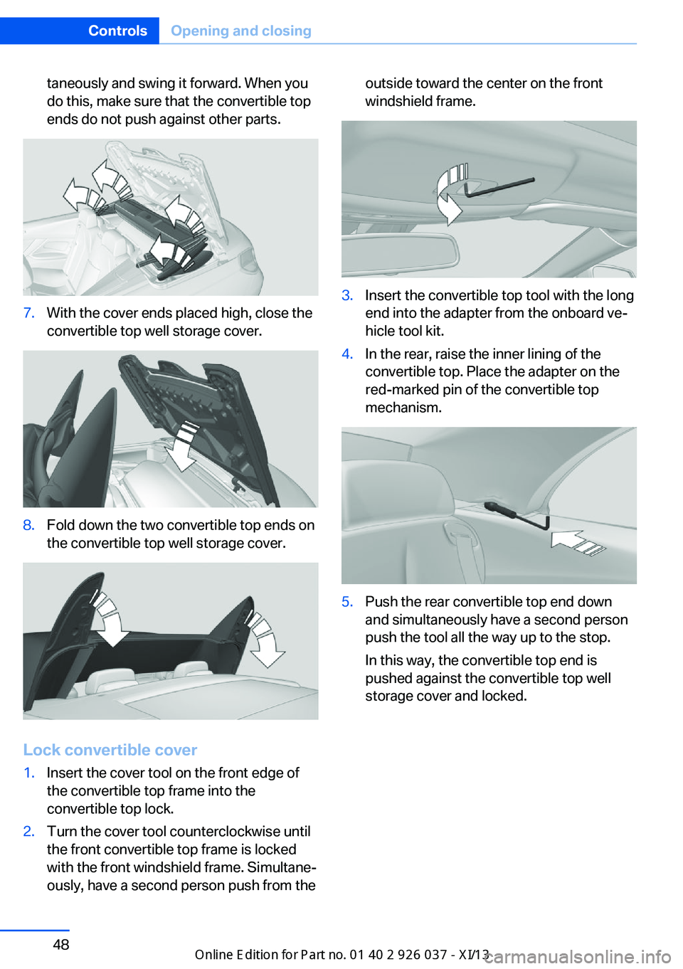
taneously and swing it forward. When you
do this, make sure that the convertible top
ends do not push against other parts.7.With the cover ends placed high, close the
convertible top well storage cover.8.Fold down the two convertible top ends on
the convertible top well storage cover.
Lock convertible cover
1.Insert the cover tool on the front edge of
the convertible top frame into the
convertible top lock.2.Turn the cover tool counterclockwise until
the front convertible top frame is locked
with the front windshield frame. Simultane‐
ously, have a second person push from theoutside toward the center on the front
windshield frame.3.Insert the convertible top tool with the long
end into the adapter from the onboard ve‐
hicle tool kit.4.In the rear, raise the inner lining of the
convertible top. Place the adapter on the
red-marked pin of the convertible top
mechanism.5.Push the rear convertible top end down
and simultaneously have a second person
push the tool all the way up to the stop.
In this way, the convertible top end is
pushed against the convertible top well
storage cover and locked.Seite 48ControlsOpening and closing48
Online Edition for Part no. 01 40 2 910 746 - VI/13
Page 55 of 222
AdjustingVehicle equipment
All standard, country-specific and optional
equipment that is offered in the model series is
described in this chapter. Therefore, equip‐
ment is also described that is not available in a
vehicle, e. g., because of the selected optional
equipment or country variant. This also applies
for safety-related functions and systems.
Sitting safely The ideal seating position can make a vital
contribution to relaxed, fatigue-free driving.
The seating position plays an important role in
an accident in combination with:▷Safety belts, refer to page 54.▷Head restraints, refer to page 55.▷Airbags, refer to page 98.
Seats
Adjusting
General information Do not adjust the seat while driving
Do not adjust the driver's seat while driv‐
ing, or the seat could respond with unexpected
movement and the ensuing loss of vehicle
control could lead to an accident.◀
Do not incline the backrest too far to the
rear
Also on the front passenger side, do not incline
the backrest on the front passenger side too
far to the rear during driving, or there is a risk of
slipping under the safety belt in the event of an
accident. This would eliminate the protection
normally provided by the belt.◀
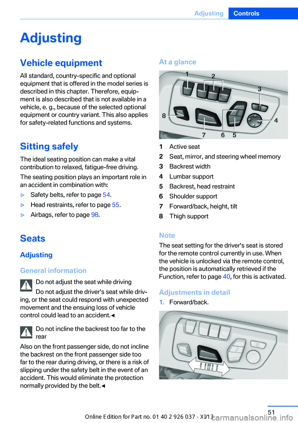
At a glance1Active seat2Seat, mirror, and steering wheel memory3Backrest width4Lumbar support5Backrest, head restraint6Shoulder support7Forward/back, height, tilt8Thigh support
Note
The seat setting for the driver's seat is stored
for the remote control currently in use. When
the vehicle is unlocked via the remote control,
the position is automatically retrieved if the
Function, refer to page 40, for this is activated.
Adjustments in detail
1.Forward/back.Seite 51AdjustingControls51
Online Edition for Part no. 01 40 2 910 746 - VI/13
Page 60 of 222
RemovingThe head restraints cannot be removed.
Entering the rear Note Folding back and locking the backrest
Before driving away, fold back and lock
the backrests; otherwise, an unexpected seat
movement may cause an accident.◀
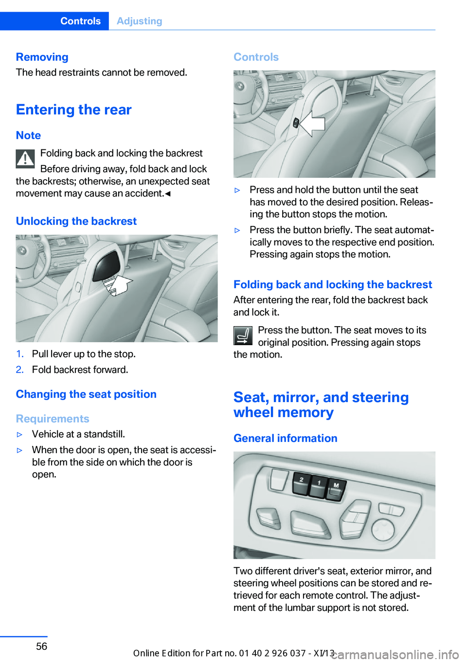
Unlocking the backrest1.Pull lever up to the stop.2.Fold backrest forward.
Changing the seat position
Requirements
▷Vehicle at a standstill.▷When the door is open, the seat is accessi‐
ble from the side on which the door is
open.Controls▷Press and hold the button until the seat
has moved to the desired position. Releas‐
ing the button stops the motion.▷Press the button briefly. The seat automat‐
ically moves to the respective end position.
Pressing again stops the motion.
Folding back and locking the backrest
After entering the rear, fold the backrest back
and lock it.
Press the button. The seat moves to its
original position. Pressing again stops
the motion.
Seat, mirror, and steering
wheel memory
General information
Two different driver's seat, exterior mirror, and
steering wheel positions can be stored and re‐
trieved for each remote control. The adjust‐
ment of the lumbar support is not stored.
Seite 56ControlsAdjusting56
Online Edition for Part no. 01 40 2 910 746 - VI/13
Page 61 of 222
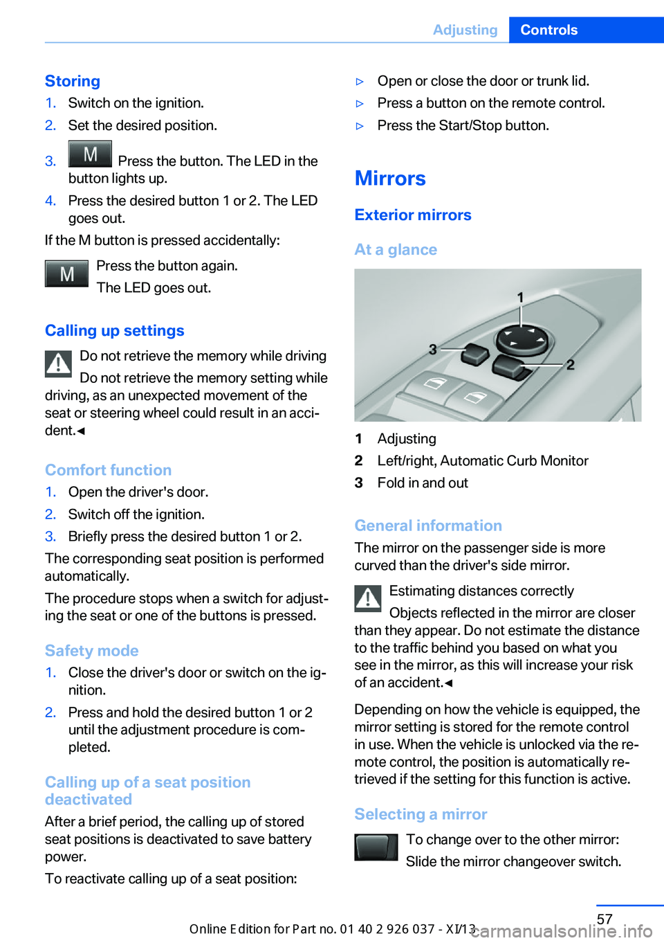
Storing1.Switch on the ignition.2.Set the desired position.3. Press the button. The LED in the
button lights up.4.Press the desired button 1 or 2. The LED
goes out.
If the M button is pressed accidentally:
Press the button again.
The LED goes out.
Calling up settings Do not retrieve the memory while driving
Do not retrieve the memory setting while
driving, as an unexpected movement of the
seat or steering wheel could result in an acci‐
dent.◀
Comfort function
1.Open the driver's door.2.Switch off the ignition.3.Briefly press the desired button 1 or 2.
The corresponding seat position is performed
automatically.
The procedure stops when a switch for adjust‐
ing the seat or one of the buttons is pressed.
Safety mode
1.Close the driver's door or switch on the ig‐
nition.2.Press and hold the desired button 1 or 2
until the adjustment procedure is com‐
pleted.
Calling up of a seat position
deactivated
After a brief period, the calling up of stored
seat positions is deactivated to save battery
power.
To reactivate calling up of a seat position:
▷Open or close the door or trunk lid.▷Press a button on the remote control.▷Press the Start/Stop button.
Mirrors
Exterior mirrors
At a glance
1Adjusting2Left/right, Automatic Curb Monitor3Fold in and out
General information
The mirror on the passenger side is more
curved than the driver's side mirror.
Estimating distances correctly
Objects reflected in the mirror are closer
than they appear. Do not estimate the distance
to the traffic behind you based on what you
see in the mirror, as this will increase your risk
of an accident.◀
Depending on how the vehicle is equipped, the
mirror setting is stored for the remote control
in use. When the vehicle is unlocked via the re‐
mote control, the position is automatically re‐
trieved if the setting for this function is active.
Selecting a mirror To change over to the other mirror:Slide the mirror changeover switch.
Seite 57AdjustingControls57
Online Edition for Part no. 01 40 2 910 746 - VI/13
Page 64 of 222

SymbolMeaning M double-clutch transmission with
Drivelogic, refer to page 70: shift
modes and Drivelogic driving pro‐
grams. Views of the Head-Up Display, refer
to page 133.
Configuring M Drive
The preassigned configurations can be individ‐
ually adjusted.
1."Settings"2."M Drive 1" or"M Drive 2"3.Select the desired setting option.4.Select the desired channel.
The individual settings are stored for the re‐
mote control currently in use.
If M Drive is activated, a change in the setting
on the Control Display is immediately adopted.
Activating/deactivating M Drive
Activating Press the corresponding button on the steer‐
ing wheel:
▷Activate M Drive 1.▷Activate M Drive 2.
If DSC OFF or MDM is set in M Drive, a mes‐
sage appears in the instrument cluster. This
message is confirmed by pressing the button
again.
Deactivating Press the corresponding button on the steer‐
ing wheel.
Indicator lamps
▷Indicator lamp comes on: corre‐
sponding M Drive is activated.▷Indicator lamp flashes: M Drive
could not be activated. Antilock
braking system ABS or Dynamic
Stability Control DSC directly regu‐
late the driving stability.
Reactivate M Drive if indicator lamp
is no longer flashing.
Notes
If M Drive is activated, individual settings can also be modified outside of M Drive, e. g. using
the buttons in the center console. This deacti‐
vates M Drive.
To reactivate all settings made for M Drive on
the Control Display, briefly press one of the fol‐
lowing buttons:
▷▷
To adopt the changed settings in M Drive,
press and hold the corresponding button.
Resetting M Drive
Individual settings can be reset to default val‐
ues.
1."Settings"2."M Drive 1" or"M Drive 2"3."Reset M Drive 1" or"Reset M Drive 2"4."Yes"
To cancel resetting: "No"
Seite 60ControlsAdjusting60
Online Edition for Part no. 01 40 2 910 746 - VI/13
Page 65 of 222
Transporting children safelyVehicle equipmentAll standard, country-specific and optional
equipment that is offered in the model series is
described in this chapter. Therefore, equip‐
ment is also described that is not available in a
vehicle, e. g., because of the selected optional
equipment or country variant. This also applies
for safety-related functions and systems.
The right place for children Note Children in the vehicle
Do not leave children unattended in the
vehicle; otherwise, they could endanger them‐
selves and other persons, e.g., by opening the
doors.◀
Children should always be in the rear
Accident research shows that the safest place
for children is in the back seat.
Transporting children in the rear
Only transport children younger than
13 years of age or shorter than 5 ft/150 cm in
the rear in child restraint fixing systems pro‐
vided in accordance with the age, weight and
size of the child; otherwise, there is an in‐
creased risk of injury in an accident.
Children 13 years of age or older must wear a
safety belt as soon as a suitable child restraint
fixing system can no longer be used, due to
their age, weight and size.◀
Children on the front passenger seat
Should it ever be necessary to use a child re‐
straint fixing system in the front passenger
seat, make sure that the front, knee and side
airbags on the front passenger side are deacti‐vated. Automatic deactivation of front passen‐
ger side airbags, refer to page 100.
Note Deactivated front passenger airbags
If a child restraint fixing system is used in
the front passenger seat, the front passenger
airbags must be deactivated; otherwise, there
is an increased risk of injury to the child when
the airbags are triggered, even with a child re‐
straint fixing system.◀
Installing child restraint
fixing systems
Hints Manufacturer's information for child re‐
straint fixing systems
To select, mount and use child restraint fixing
systems, observe the information provided by
the system manufacturer; otherwise, the pro‐
tective effect can be impaired.◀
Lock the rear seat backrests in position
Before installing a child restraint system,
make sure that the rear seat backrests are
locked; otherwise, the protective effect is not
guaranteed and there is an increased risk of in‐
jury for the child in the event of an accident.◀
On the front passenger seat
Deactivating airbags
After installing a child restraint fixing system in
the front passenger seat, make sure that the
front, knee and side airbags on the front pas‐
senger side are deactivated.
Deactivate the front passenger airbags auto‐
matically, refer to page 100.Seite 61Transporting children safelyControls61
Online Edition for Part no. 01 40 2 910 746 - VI/13
Page 66 of 222
Deactivating the front passenger airbags
If a child restraint fixing system is used in
the front passenger seat, the front passenger
airbags must be deactivated; otherwise, there
is an increased risk of injury to the child when
the airbags are triggered, even with a child re‐
straint fixing system.◀
Seat position and height
Before installing a child restraint fixing system,
move the front passenger seat as far back as
possible and adjust its height to the highest
position to obtain the best possible position for
the belt and to offer optimal protection in the
event of an accident.
Do not change the seat position and height af‐
ter this.
Backrest width Adjustable backrest width: before installing a
child restraint fixing system in the front pas‐
senger seat, open the backrest width com‐
pletely. Do not change the backrest width
again and do not call up a memory position.
Backrest width for the child seat
Before installing a child restraint fixing
system in the front passenger seat, the back‐
rest width must be opened completely. Do not
change the adjustment after this; otherwise,
the stability of the child seat will be reduced.◀Child seat security
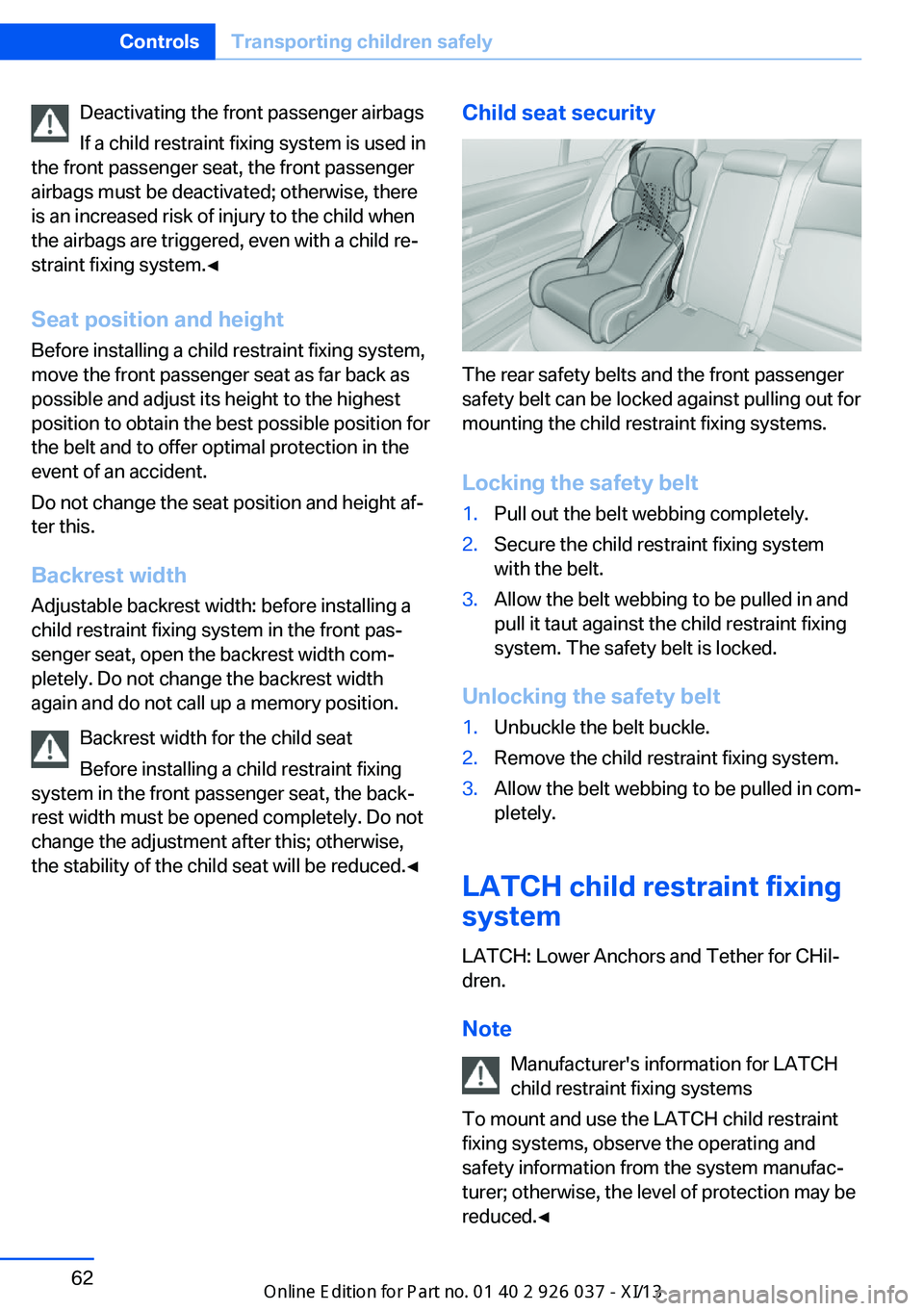
The rear safety belts and the front passenger
safety belt can be locked against pulling out for
mounting the child restraint fixing systems.
Locking the safety belt
1.Pull out the belt webbing completely.2.Secure the child restraint fixing system
with the belt.3.Allow the belt webbing to be pulled in and
pull it taut against the child restraint fixing
system. The safety belt is locked.
Unlocking the safety belt
1.Unbuckle the belt buckle.2.Remove the child restraint fixing system.3.Allow the belt webbing to be pulled in com‐
pletely.
LATCH child restraint fixing
system
LATCH: Lower Anchors and Tether for CHil‐dren.
Note Manufacturer's information for LATCH
child restraint fixing systems
To mount and use the LATCH child restraint
fixing systems, observe the operating and
safety information from the system manufac‐
turer; otherwise, the level of protection may be
reduced.◀
Seite 62ControlsTransporting children safely62
Online Edition for Part no. 01 40 2 910 746 - VI/13
Page 68 of 222
DrivingVehicle equipment
All standard, country-specific and optional
equipment that is offered in the model series is
described in this chapter. Therefore, equip‐
ment is also described that is not available in a
vehicle, e. g., because of the selected optional
equipment or country variant. This also applies
for safety-related functions and systems.
Start/Stop button The concept Pressing the Start/Stop button
switches the ignition on or off
and starts the engine.
Double-clutch transmission:
The engine starts if the brake is
depressed while pressing the Start/Stop but‐
ton.
Manual transmission: the engine starts if the
clutch pedal is depressed when the Start/Stop
button is pressed.
Ignition onDouble-clutch transmission: Press the Start/
Stop button but do not depress the brake.
Manual-shift transmission: press the Start/
Stop button, and do not press on the clutch
pedal at the same time.
All vehicle systems are ready for operation.
Most of the indicator and warning lamps in the
instrument cluster light up for varying lengths
of time.
To save battery power when the engine is off,
switch off the ignition and any unnecessary
electronic systems/power consumers.
The ignition switches off automatically:▷When locking the vehicle, even if the low
beams are switched on.▷Shortly before the battery is discharged
completely, so that the engine can still be
started.
Note
If the engine is switched off and the ignition is
switched on, the system automatically
switches to the radio ready state when the
door is opened if the lights are switched off or
the daytime running lights are switched on.
Ignition off
Double-clutch transmission: Press the Start/
Stop button again, but do not depress the
brake.
Manual-shift transmission: press the Start/
Stop button again, and do not press on the
clutch pedal at the same time.
All indicator lamps in the instrument cluster go
out.
To save battery power when the engine is off,
switch off the ignition and any unnecessary
electronic systems/power consumers.
Transmission position P with the ignition
off
When the ignition is switched off, position P is
engaged automatically. When in an automatic
car wash, for example, ensure that the ignition
is not switched off accidentally.◀
The ignition automatically cuts off while the
vehicle is stationary and the engine is stopped:
▷When locking the vehicle, and when the
low beams are activated.▷Shortly before the battery is discharged
completely, so that the engine can still be
started. This function is only available
when the low beams are switched off.Seite 64ControlsDriving64
Online Edition for Part no. 01 40 2 910 746 - VI/13
Page 69 of 222
▷When opening or closing the driver door, if
the driver's seat belt is unbuckled and the
low beams are switched off.▷While the driver's seat belt is unbuckled, if
the driver's door is open and the low
beams are switched off.
When the ignition is switched off, by opening
or closing the driver's door or unbuckling the
driver's seat belt, the radio ready state remains
active.
Radio ready state
Activate radio ready state:
▷When the engine is running: press the
Start/Stop button.
Some electronic systems/power consumers
remain ready for operation.
The radio ready state switches off automati‐
cally:
▷After approx. 8 minutes.▷When the vehicle is locked using the cen‐
tral locking system.▷Shortly before the battery is discharged
completely, so that the engine can still be
started.
Starting the engine
Hints Enclosed areas
Do not let the engine run in enclosed
areas; otherwise, breathing of exhaust fumes may lead to loss of consciousness and death.
The exhaust gases contain carbon monoxide,
an odorless and colorless but highly toxic
gas.◀
Unattended vehicle
Do not leave the vehicle unattended with
the engine running; doing so poses a risk of
danger.
Before leaving the vehicle with the engine run‐
ning, set the parking brake and engage trans‐
mission position P; otherwise, the vehicle may
begin to roll.◀
Repeated starting in quick succession
Avoid repeated unsuccessful attempts to
start the vehicle or starting the vehicle several
times in quick succession. Otherwise, the fuel
is not burned or is inadequately burned, posing
a risk of overheating and damage to the cata‐
lytic converter.◀
Do not wait for the engine to warm-up while
the vehicle remains stationary. Start driving at
moderate engine speeds.
Manual transmission
Starting the engine1.Depress the brake pedal.2.Press on the clutch pedal and shift to neu‐
tral.3.Press the Start/Stop button.
The ignition is activated automatically for a
certain time and is stopped as soon as the en‐
gine starts.
Double-clutch transmission
Starting the engine
1.Depress the brake pedal.2.Press the Start/Stop button.
The ignition is activated automatically for a
certain time and is stopped as soon as the en‐
gine starts.
Seite 65DrivingControls65
Online Edition for Part no. 01 40 2 910 746 - VI/13
Page 71 of 222
The display indicates that the
conditions for an automatic en‐
gine stop have not been satis‐
fied.
Note
The engine is not switched off automatically in
the following situations:▷External temperature too low.▷The external temperature is high and auto‐
matic climate control is running.▷The passenger compartment has not yet
been heated or cooled to the required
level.▷The engine is not yet at operating temper‐
ature.▷The wheels are at a sharp angle or the
steering wheel is being turned.▷After driving in reverse.▷Fogging of the windows when the auto‐
matic climate control is switched on.▷Vehicle battery is heavily discharged.▷The engine compartment lid is unlocked.▷Stop-and-go traffic.▷Use of fuel with high ethanol content.
Starting the engine
The engine starts automatically under the fol‐
lowing conditions:
▷Manual transmission:
The clutch pedal is pressed.▷Double-clutch transmission:
By releasing the brake pedal.
After the engine starts, accelerate as usual.
Safety mode
After the engine switches off automatically, it
will not start again automatically if any one of
the following conditions are met.
▷The driver's safety belt is unbuckled and
the driver's door is open.▷The hood was unlocked.
Some indicator lamps light up for varying
lengths of time.
The engine can only be started via the Start/
Stop button.
Note Even if driving away was not intended, the de‐
activated engine starts up automatically in the
following situations:
▷Excessive warming of the passenger com‐
partment when the cooling function is
switched on.▷The steering wheel is turned.▷Double-clutch transmission: Change of the
transmission from D to N, R or D/S.▷Double-clutch transmission: Accelerating
while simultaneously applying the brake.▷Fogging of the windows when the auto‐
matic climate control is switched on.▷Vehicle battery is heavily discharged.▷Excessive cooling of the passenger com‐
partment when the heating is switched on.
Preventing an automatic engine stop with a double-clutch transmission
The concept To make it possible to drive away very quickly,
such as at an intersection, the automatic en‐
gine stop can be actively prevented.
Preventing an engine stop using the
brake pedal
The engine stop can be actively prevented
within one second after the vehicle comes to a
standstill.
▷Immediately after the vehicle comes to a
standstill, briefly press the brake pedal
forcefully.Seite 67DrivingControls67
Online Edition for Part no. 01 40 2 910 746 - VI/13