Breakdown BMW M6 CONVERTIBLE 2014 F12M Owner's Manual
[x] Cancel search | Manufacturer: BMW, Model Year: 2014, Model line: M6 CONVERTIBLE, Model: BMW M6 CONVERTIBLE 2014 F12MPages: 228, PDF Size: 5.02 MB
Page 9 of 228
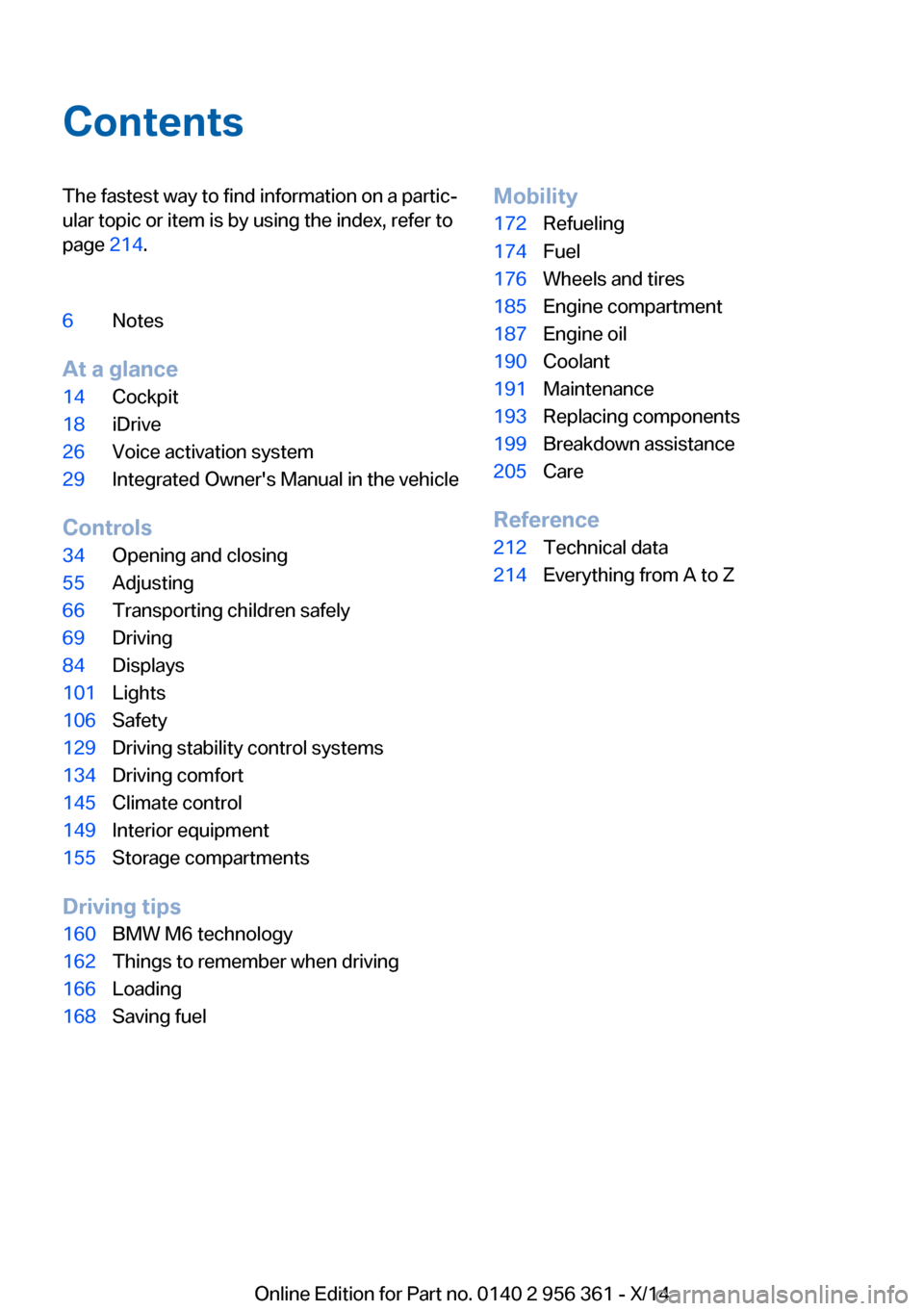
ContentsThe fastest way to find information on a partic‐
ular topic or item is by using the index, refer to
page 214.6Notes
At a glance
14Cockpit18iDrive26Voice activation system29Integrated Owner's Manual in the vehicle
Controls
34Opening and closing55Adjusting66Transporting children safely69Driving84Displays101Lights106Safety129Driving stability control systems134Driving comfort145Climate control149Interior equipment155Storage compartments
Driving tips
160BMW M6 technology162Things to remember when driving166Loading168Saving fuelMobility172Refueling174Fuel176Wheels and tires185Engine compartment187Engine oil190Coolant191Maintenance193Replacing components199Breakdown assistance205Care
Reference
212Technical data214Everything from A to Z
Online Edition for Part no. 0140 2 956 361 - X/14
Page 33 of 228
Integrated Owner's Manual in the vehicleVehicle features and optionsThis chapter describes all standard, country-
specific and optional features offered with the
series. It also describes features that are not
necessarily available in your car, e. g., due to
the selected options or country versions. This
also applies to safety-related functions and
systems.
Integrated Owner's Manual
in the vehicle
The Integrated Owner's Manual can be dis‐
played on the Control Display. It specifically
describes features and functions found in the
vehicle.
Components of the Integrated Owner's Manual
The Integrated Owner's Manual consists of
three parts, which offer various levels of infor‐
mation or possible access.
Quick Reference Guide
The Quick Reference Guide provides informa‐
tion how to operate the car, how to use basic
vehicle functions or what to do in case of a
breakdown. This information can also be dis‐
played while driving.
Search by images
Image search provides information and de‐
scriptions. This is helpful when the terminol‐
ogy for a feature is not at hand.
Owner's Manual
Search for information and descriptions by en‐
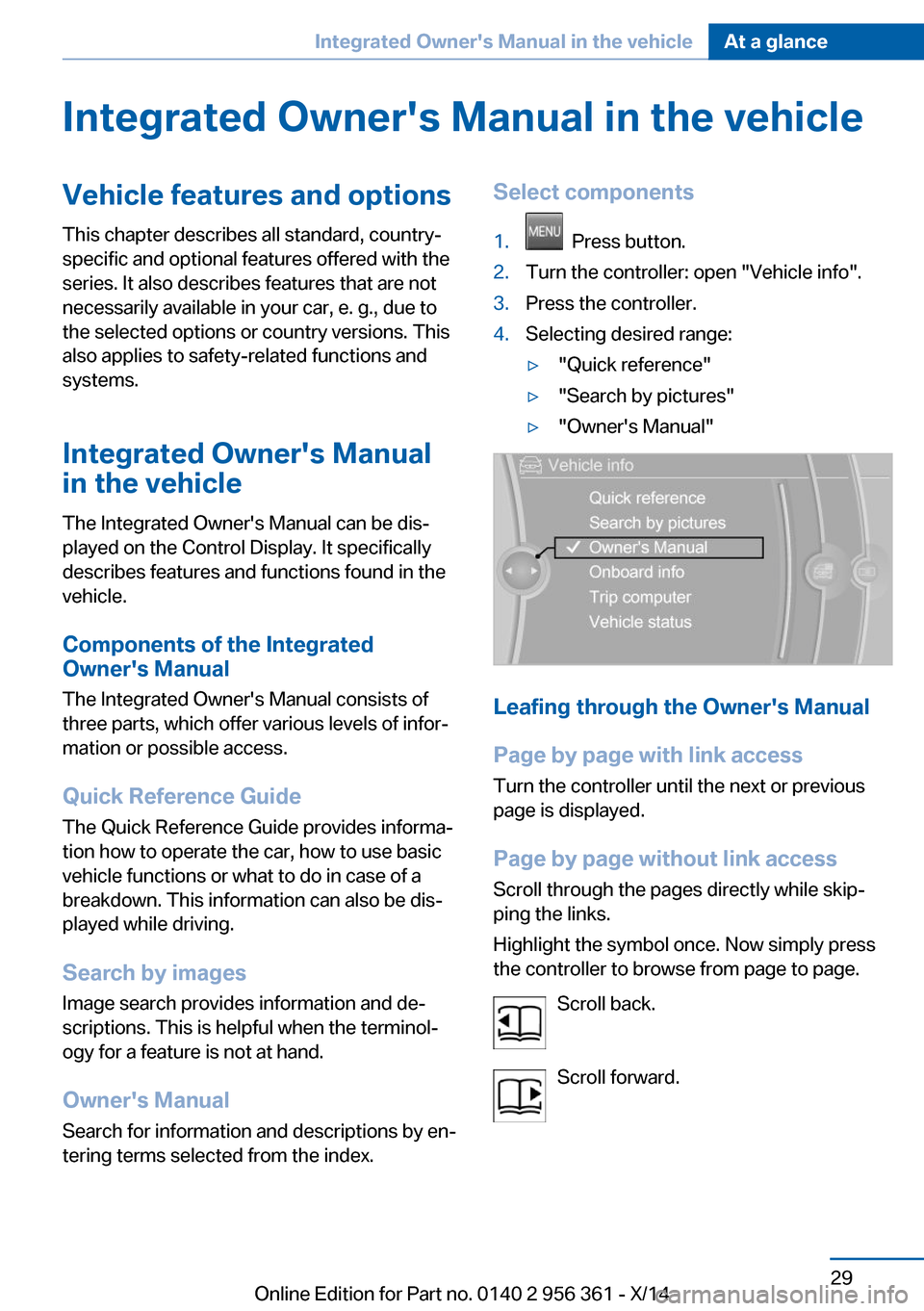
tering terms selected from the index.Select components1. Press button.2.Turn the controller: open "Vehicle info".3.Press the controller.4.Selecting desired range:▷"Quick reference"▷"Search by pictures"▷"Owner's Manual"
Leafing through the Owner's Manual
Page by page with link access
Turn the controller until the next or previous
page is displayed.
Page by page without link access
Scroll through the pages directly while skip‐
ping the links.
Highlight the symbol once. Now simply press
the controller to browse from page to page.
Scroll back.
Scroll forward.
Seite 29Integrated Owner's Manual in the vehicleAt a glance29
Online Edition for Part no. 0140 2 956 361 - X/14
Page 185 of 228
Retreaded tires
Possibly substantial variations in the de‐
sign and age of the tire casing structures can
limit service life and have a negative impact on
road safety.◀
Winter tires
Winter tires are recommended for operating on
winter roads.
Although so-called all-season M+S tires pro‐
vide better winter traction than summer tires, they do not provide the same level of perform‐
ance as winter tires.
Maximum speed of winter tires If the maximum speed of the vehicle is higher
than the permissible speed for the winter tires,
then a respective symbol is displayed in your
field of vision. You can obtain this sign from the
tire specialist or from your service center.
Maximum speed for winter tires
Do not exceed the maximum speed for
the respective winter tires; otherwise, tire dam‐
age and accidents can occur.◀
Rotating wheels between axles The manufacturer of your vehicle advises
against switching wheels between the front
and rear axles. This can impair the handling
characteristics.
Rotating the tires is not permissible on vehi‐
cles with different tire sizes on the front and
rear axles, i.e. when using different types of
tires.
Storage Store wheels and tires in a cool, dry place with
as little exposure to light as possible.
Always protect tires against all contact with oil,
grease and fuels.
Do not exceed the maximum tire inflation pres‐
sure indicated on the side wall of the tire.Repairing a flat tire
Safety measures in case of a breakdown
Park the vehicle as far away as possible
from passing traffic and on solid ground.
Switch on the hazard warning system.
Turn the steering wheel until the front wheels are in the straight-ahead position and engage
the steering wheel lock.
Secure the vehicle against rolling away by set‐
ting the parking brake.
Have all vehicle occupants get out of the vehi‐
cle and ensure that they remain outside the
immediate area in a safe place, such as behind
a guardrail.
If necessary, set up a warning triangle at an ap‐
propriate distance.
Comply with all safety guidelines and regula‐
tions.◀
Mobility System
The concept With the Mobility System, minor tire damage
can be sealed quickly to enable continued
travel. To accomplish this, sealant is pumped
into the tires, which seals the damage from the
inside.
The compressor can be used to check the tire
inflation pressure.
Hints▷Follow the instructions on using the Mobi‐
lity System found on the compressor and
sealant container.▷Use of the Mobility System may be ineffec‐
tive if the tire puncture measures approx.
1/8 in/4 mm or more.▷Contact the nearest service center if the
tire cannot be made drivable.Seite 181Wheels and tiresMobility181
Online Edition for Part no. 0140 2 956 361 - X/14
Page 203 of 228
Breakdown assistanceVehicle features and options
This chapter describes all standard, country-
specific and optional features offered with the
series. It also describes features that are not
necessarily available in your car, e. g., due to
the selected options or country versions. This
also applies to safety-related functions and
systems.
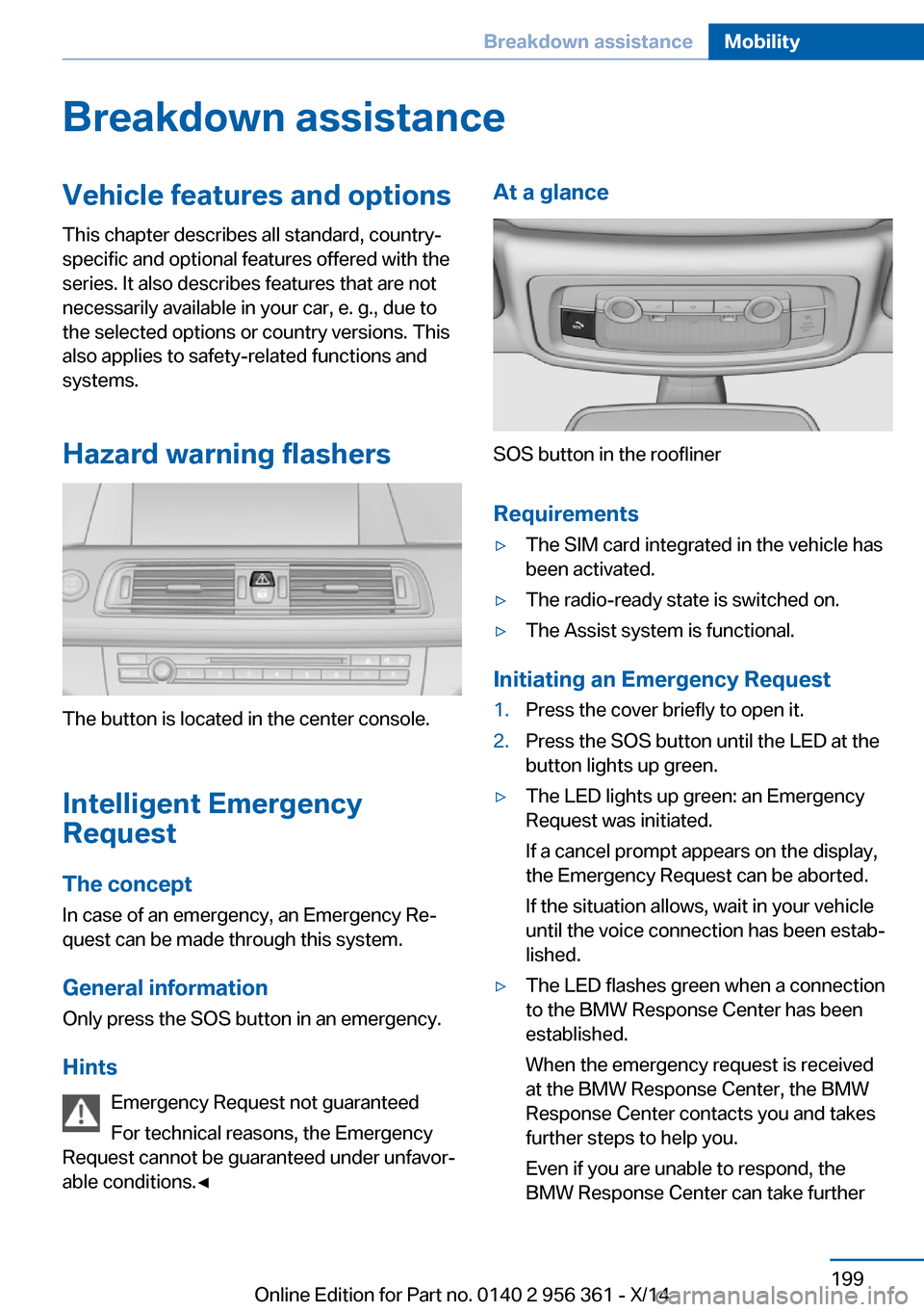
Hazard warning flashers
The button is located in the center console.
Intelligent Emergency
Request
The concept In case of an emergency, an Emergency Re‐
quest can be made through this system.
General information
Only press the SOS button in an emergency.
Hints Emergency Request not guaranteed
For technical reasons, the Emergency
Request cannot be guaranteed under unfavor‐
able conditions.◀
At a glance
SOS button in the roofliner
Requirements
▷The SIM card integrated in the vehicle has
been activated.▷The radio-ready state is switched on.▷The Assist system is functional.
Initiating an Emergency Request
1.Press the cover briefly to open it.2.Press the SOS button until the LED at the
button lights up green.▷The LED lights up green: an Emergency
Request was initiated.
If a cancel prompt appears on the display,
the Emergency Request can be aborted.
If the situation allows, wait in your vehicle
until the voice connection has been estab‐
lished.▷The LED flashes green when a connection
to the BMW Response Center has been
established.
When the emergency request is received
at the BMW Response Center, the BMW
Response Center contacts you and takes
further steps to help you.
Even if you are unable to respond, the
BMW Response Center can take furtherSeite 199Breakdown assistanceMobility199
Online Edition for Part no. 0140 2 956 361 - X/14
Page 204 of 228
steps to help you under certain circum‐
stances.
For this, data are transmitted to the BMW
Response Center which serve to deter‐
mine the necessary rescue measures. E. g.
the current position of the vehicle, if it can
be established.▷If the LED is flashing green, but the BMW
Response Center can no longer be heard
via the speaker, you can nevertheless still
be heard at the BMW Response Center.
Initiating an Emergency Request
automatically
Under certain conditions, an Emergency Re‐
quest is automatically initiated immediately af‐
ter a severe accident. Automatic Collision Noti‐
fication is not affected by pressing the SOS
button.
Warning triangle
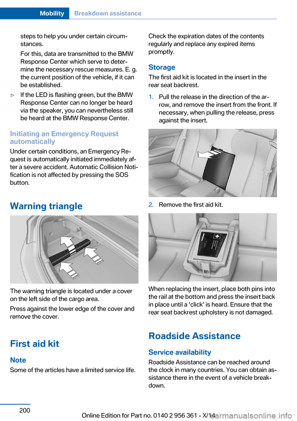
The warning triangle is located under a cover
on the left side of the cargo area.
Press against the lower edge of the cover and
remove the cover.
First aid kit NoteSome of the articles have a limited service life.
Check the expiration dates of the contents
regularly and replace any expired items
promptly.
Storage The first aid kit is located in the insert in the
rear seat backrest.1.Pull the release in the direction of the ar‐
row, and remove the insert from the front. If
necessary, when pulling the release, press
against the insert.2.Remove the first aid kit.
When replacing the insert, place both pins into
the rail at the bottom and press the insert back
in place until a 'click' is heard. Ensure that the
rear seat backrest upholstery is not damaged.
Roadside Assistance
Service availability Roadside Assistance can be reached around
the clock in many countries. You can obtain as‐
sistance there in the event of a vehicle break‐
down.
Seite 200MobilityBreakdown assistance200
Online Edition for Part no. 0140 2 956 361 - X/14
Page 205 of 228
Roadside AssistanceThe Roadside Assistance phone number can
be viewed on the iDrive or a connection to
Roadside Assistance can be established di‐
rectly.
Jump-starting
Hints
If the battery is discharged, an engine can be
started using the battery of another vehicle
and two jumper cables. Only use jumper ca‐
bles with fully insulated clamp handles.
To prevent personal injury or damage to both
vehicles, adhere strictly to the following proce‐
dure.
Do not touch live parts
To avoid the risk of potentially fatal in‐
jury, always avoid all contact with electrical
components while the engine is running.◀
Preparation1.Check whether the battery of the other ve‐
hicle has a voltage of 12 volts. This infor‐
mation can be found on the battery.2.Switch off the engine of the assisting vehi‐
cle.3.Switch off any electronic systems/power
consumers in both vehicles.
Bodywork contact between vehicles
Make sure that there is no contact be‐
tween the bodywork of the two vehicles; other‐
wise, there is a danger of short circuits.◀
Starting aid terminals Connecting order
Connect the jumper cables in the correct
order to prevent risk of injury from arcing.◀
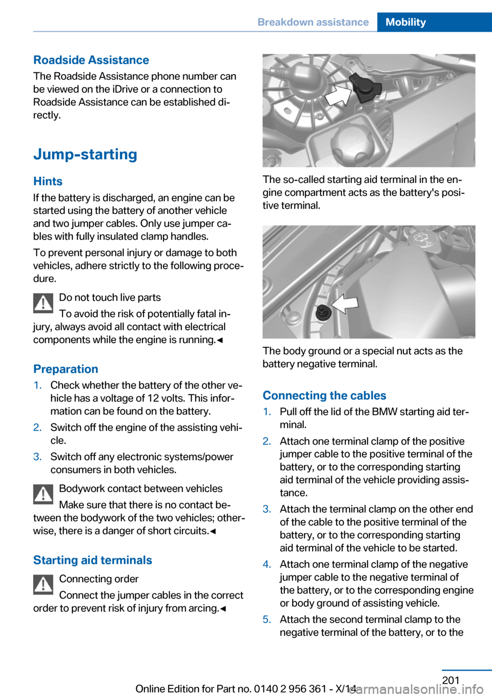
The so-called starting aid terminal in the en‐
gine compartment acts as the battery's posi‐
tive terminal.
The body ground or a special nut acts as the
battery negative terminal.
Connecting the cables
1.Pull off the lid of the BMW starting aid ter‐
minal.2.Attach one terminal clamp of the positive
jumper cable to the positive terminal of the
battery, or to the corresponding starting
aid terminal of the vehicle providing assis‐
tance.3.Attach the terminal clamp on the other end
of the cable to the positive terminal of the
battery, or to the corresponding starting
aid terminal of the vehicle to be started.4.Attach one terminal clamp of the negative
jumper cable to the negative terminal of
the battery, or to the corresponding engine
or body ground of assisting vehicle.5.Attach the second terminal clamp to the
negative terminal of the battery, or to theSeite 201Breakdown assistanceMobility201
Online Edition for Part no. 0140 2 956 361 - X/14
Page 206 of 228
corresponding engine or body ground of
the vehicle to be started.
Starting the engine
Never use spray fluids to start the engine.
1.Start the engine of the assisting vehicle
and let it run for several minutes at an in‐
creased idle speed.2.Start the engine of the vehicle that is to be
started in the usual way.
If the first starting attempt is not success‐
ful, wait a few minutes before making an‐
other attempt in order to allow the dis‐
charged battery to recharge.3.Let both engines run for several minutes.4.Disconnect the jumper cables in the re‐
verse order.
Check the battery and recharge if needed.
Tow-starting and towing Note Tow-starting and towing
For towing the vehicle turn, switch off the
Intelligent Safety systems; otherwise malfunc‐
tions of the individual braking systems might
lead to accidents.◀
Manual transmission
Observe before towing your vehicle Gearshift lever in neutral position.
Towing When the parking brake is blocked
The parking brake cannot be released
manually.
Do not tow the vehicle with the parking brake
blocked, or the vehicle can be damaged.
Contact your service center.◀
Follow the towing instructions
Follow all towing instructions; otherwise,
vehicle damage or accidents may occur.◀▷Make sure that the ignition is switched on;
otherwise, the low beams, tail lights, turn
signals, and wipers may be unavailable.▷Do not tow the vehicle with the rear axle
tilted, as the front wheels could turn.▷When the engine is stopped, there is no
power assist. Consequently, more force
needs to be applied when braking and
steering.▷Larger steering wheel movements are re‐
quired.▷The towing vehicle must not be lighter
than the vehicle being towed; otherwise,
it will not be possible to control the vehi‐
cle's response.
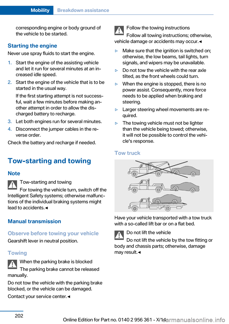
Tow truck
Have your vehicle transported with a tow truck
with a so-called lift bar or on a flat bed.
Do not lift the vehicle
Do not lift the vehicle by the tow fitting or
body and chassis parts; otherwise, damage
may result.◀
Seite 202MobilityBreakdown assistance202
Online Edition for Part no. 0140 2 956 361 - X/14
Page 207 of 228
M double-clutch transmission:
transporting your vehicle
Note Your vehicle is not permitted to be towed.
Therefore, contact a service center in the
event of a breakdown.
Do not have the vehicle towed
Have your vehicle transported on a load‐
ing platform only; otherwise, damage may oc‐
cur.◀
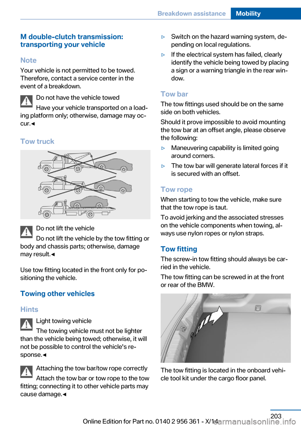
Tow truck
Do not lift the vehicle
Do not lift the vehicle by the tow fitting or
body and chassis parts; otherwise, damage
may result.◀
Use tow fitting located in the front only for po‐
sitioning the vehicle.
Towing other vehicles
Hints Light towing vehicle
The towing vehicle must not be lighter
than the vehicle being towed; otherwise, it will
not be possible to control the vehicle's re‐
sponse.◀
Attaching the tow bar/tow rope correctly
Attach the tow bar or tow rope to the tow
fitting; connecting it to other vehicle parts may
cause damage.◀
▷Switch on the hazard warning system, de‐
pending on local regulations.▷If the electrical system has failed, clearly
identify the vehicle being towed by placing
a sign or a warning triangle in the rear win‐
dow.
Tow bar
The tow fittings used should be on the same
side on both vehicles.
Should it prove impossible to avoid mounting
the tow bar at an offset angle, please observe
the following:
▷Maneuvering capability is limited going
around corners.▷The tow bar will generate lateral forces if it
is secured with an offset.
Tow rope
When starting to tow the vehicle, make sure
that the tow rope is taut.
To avoid jerking and the associated stresses
on the vehicle components when towing, al‐
ways use nylon ropes or nylon straps.
Tow fitting
The screw-in tow fitting should always be car‐
ried in the vehicle.
The tow fitting can be screwed in at the front
or rear of the BMW.
The tow fitting is located in the onboard vehi‐
cle tool kit under the cargo floor panel.
Seite 203Breakdown assistanceMobility203
Online Edition for Part no. 0140 2 956 361 - X/14
Page 208 of 228
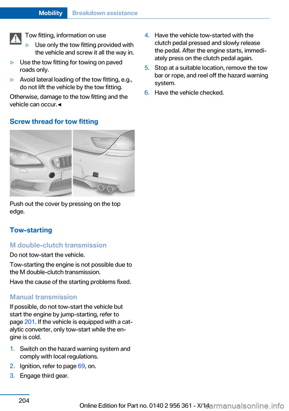
Tow fitting, information on use▷Use only the tow fitting provided with
the vehicle and screw it all the way in.▷Use the tow fitting for towing on paved
roads only.▷Avoid lateral loading of the tow fitting, e.g.,
do not lift the vehicle by the tow fitting.
Otherwise, damage to the tow fitting and the
vehicle can occur.◀
Screw thread for tow fitting
Push out the cover by pressing on the top
edge.
Tow-starting
M double-clutch transmission
Do not tow-start the vehicle.
Tow-starting the engine is not possible due to
the M double-clutch transmission.
Have the cause of the starting problems fixed.
Manual transmission
If possible, do not tow-start the vehicle but
start the engine by jump-starting, refer to
page 201. If the vehicle is equipped with a cat‐
alytic converter, only tow-start while the en‐
gine is cold.
1.Switch on the hazard warning system and
comply with local regulations.2.Ignition, refer to page 69, on.3.Engage third gear.4.Have the vehicle tow-started with the
clutch pedal pressed and slowly release
the pedal. After the engine starts, immedi‐
ately press on the clutch pedal again.5.Stop at a suitable location, remove the tow
bar or rope, and reel off the hazard warning
system.6.Have the vehicle checked.Seite 204MobilityBreakdown assistance204
Online Edition for Part no. 0140 2 956 361 - X/14
Page 219 of 228
Braking, hints 164
Breakdown assis‐ tance 199, 200
Break-in 162
Brightness of Control Dis‐ play 98
Bulb replacement, front 193
Bulb replacement, rear 195
Button, Start/Stop 69
Bypassing, refer to Jump- starting 201
C
California Proposition 65 Warning 7
Calling up mirror adjust‐ ment 43
Calling up seat adjust‐ ment 43
Calling up steering wheel ad‐ justment 43
Camera, care 209
Camera, rearview cam‐ era 139
Camera, Side View 141
Camera, Top View 143
Can holder, refer to Cu‐ pholder 157
Car battery 197
Carbon ceramic brake M 160
Car care products 206
Care, displays 209
Care, vehicle 206
Cargo 166
Cargo area partition 50
Cargo area, storage compart‐ ments 157
Cargo, securing 167
Cargo straps, securing cargo 167
Car key, refer to Remote con‐ trol 34
Carpet, care 208
Car wash 205 Catalytic converter, refer to
Hot exhaust system 163
CBS Condition Based Serv‐ ice 191
CD/Multimedia, see user's manual for Navigation, En‐
tertainment and Communi‐
cation
Center console 16
Central locking system 40
Central screen, refer to Con‐ trol Display 18
Ceramic brake 160
Changes, technical, refer to Safety 7
Changing parts 193
Changing wheels 196
Changing wheels/tires 180
Chassis number, see vehicle identification number 9
Check Control 85
Checking the engine oil level electronically 187
Checking the oil level elec‐ tronically 187
Children, seating position 66
Children, transporting safely 66
Child restraint fixing sys‐ tem 66
Child restraint fixing system LATCH 67
Child restraint fixing systems, mounting 66
Child seat, mounting 66
Child seats 66
Chrome parts, care 208
Cigarette lighter 151
Cleaning displays 209
Climate control 145
Climate control wind‐ shield 163
Clock 89
Closing/opening via door lock 39 Closing/opening with remote
control 37
Clothes hooks 156
Combination reel, refer to Turn signals 75
Combination reel, refer to Wiper system 75
Comfort Access 41
Compound brake 160
Compressor 181
Computer 95
Condensation on win‐ dows 146
Condensation under the vehi‐ cle 165
Condition Based Service CBS 191
Confirmation signal 43
ConnectedDrive, see user's manual for Navigation, En‐
tertainment and Communi‐
cation
ConnectedDrive Services
Control Display 18
Control Display, settings 97
Controller 18
Control systems, driving sta‐ bility 129
Convenient closing with the remote control 38
Convenient opening with the remote control 37
Convertible, convertible top 47
Convertible mode, automatic climate control 146
Convertible program, auto‐ matic climate control 146
Convertible top 47
Convertible top, care 207
Convertible top, cargo area partition 50
Convertible top, emergency operation 50
Convertible top, rollover pro‐ tection system 109 Seite 215Everything from A to ZReference215
Online Edition for Part no. 0140 2 956 361 - X/14