sensor BMW M6 CONVERTIBLE 2015 F12M User Guide
[x] Cancel search | Manufacturer: BMW, Model Year: 2015, Model line: M6 CONVERTIBLE, Model: BMW M6 CONVERTIBLE 2015 F12MPages: 230, PDF Size: 4.9 MB
Page 129 of 230
At a glance
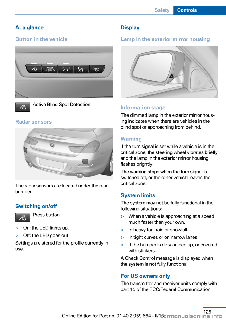
Button in the vehicle
Active Blind Spot Detection
Radar sensors
The radar sensors are located under the rear
bumper.
Switching on/off Press button.
▷On: the LED lights up.▷Off: the LED goes out.
Settings are stored for the profile currently in
use.
Display
Lamp in the exterior mirror housing
Information stage
The dimmed lamp in the exterior mirror hous‐
ing indicates when there are vehicles in the
blind spot or approaching from behind.
Warning If the turn signal is set while a vehicle is in the
critical zone, the steering wheel vibrates briefly
and the lamp in the exterior mirror housing
flashes brightly.
The warning stops when the turn signal is
switched off, or the other vehicle leaves the
critical zone.
System limits
The system may not be fully functional in the
following situations:
▷When a vehicle is approaching at a speed
much faster than your own.▷In heavy fog, rain or snowfall.▷In tight curves or on narrow lanes.▷If the bumper is dirty or iced up, or covered
with stickers.
A Check Control message is displayed when
the system is not fully functional.
For US owners only The transmitter and receiver units comply with
part 15 of the FCC/Federal Communication
Seite 125SafetyControls125
Online Edition for Part no. 01 40 2 959 664 - II/15
Page 140 of 230
ment cluster indicates whether the system is
switched on.
Desired speed▷The marking lights up green:
the system is active.▷The marking lights up or‐
ange: the system has been
interrupted.▷The marking does not light up: the system
is switched off.
Brief status display
Selected desired speed.
If --- appears briefly on the display for Check
Control messages, it is possible that the sys‐
tem requirements are currently not ready for
operations.
Displays in the Head-up Display Some system information can also be dis‐played in the Head-up Display.
PDC Park Distance Control
The concept PDC is a support when parking. When you
slowly approach an object in the rear - or also
in the front of the vehicle if the feature is availa‐
ble - then the object is reported through:
▷Signal tones.▷Visual display.
General information
Ultrasound sensors in the bumpers measure
the distances from objects.
The maneuvering range, depending on the ob‐
stacle and environmental conditions, is approx.
6 ft/2 m.
An acoustic warning is first given:▷By the front sensors and the two rear cor‐
ner sensors at approx. 24 in/60 cm.▷By the rear middle sensors at approx.
5 ft/1.50 m.
To ensure full functionality:
▷Do not cover sensors, e.g., with stickers,
bicycle racks.▷Keep the sensors clean and free of ice.▷When using high-pressure washers, do not
spray the sensors for long periods and
maintain a distance of at least 12 in/30 cm.
Hints
Personal responsibility
Even an active system does not relieve
the driver from personal responsibility while
driving.
Technically the system has its limits, it cannot
independently react to all traffic situations.
Monitor your driving, be on the alert, observe
the vehicle surroundings and other traffic and
react when needed - risk of accident.◀
Avoid driving fast with PDC
Avoid approaching an object too fast.
Avoid driving off fast while PDC is not yet ac‐
tive.
For technical reasons, the system may other‐
wise be too late in issuing a warning.◀
Seite 136ControlsDriving comfort136
Online Edition for Part no. 01 40 2 959 664 - II/15
Page 141 of 230
Overview
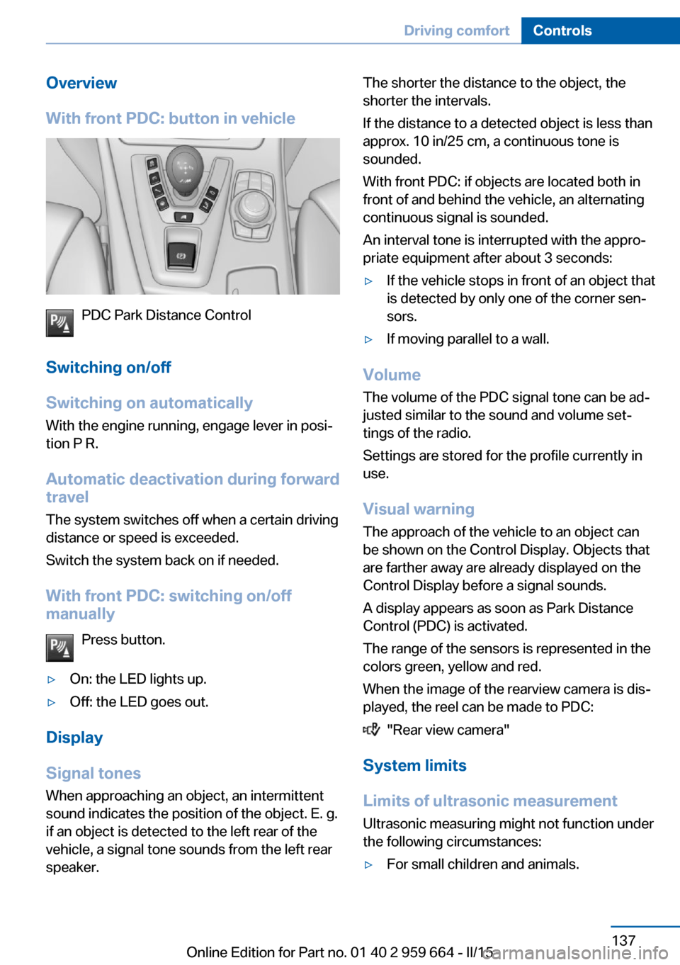
With front PDC: button in vehicle
PDC Park Distance Control
Switching on/off
Switching on automatically With the engine running, engage lever in posi‐
tion P R.
Automatic deactivation during forward
travel
The system switches off when a certain driving
distance or speed is exceeded.
Switch the system back on if needed.
With front PDC: switching on/off
manually
Press button.
▷On: the LED lights up.▷Off: the LED goes out.
Display
Signal tones When approaching an object, an intermittent
sound indicates the position of the object. E. g.
if an object is detected to the left rear of the
vehicle, a signal tone sounds from the left rear
speaker.
The shorter the distance to the object, the
shorter the intervals.
If the distance to a detected object is less than
approx. 10 in/25 cm, a continuous tone is
sounded.
With front PDC: if objects are located both in
front of and behind the vehicle, an alternating
continuous signal is sounded.
An interval tone is interrupted with the appro‐
priate equipment after about 3 seconds:▷If the vehicle stops in front of an object that
is detected by only one of the corner sen‐
sors.▷If moving parallel to a wall.
Volume
The volume of the PDC signal tone can be ad‐
justed similar to the sound and volume set‐
tings of the radio.
Settings are stored for the profile currently in
use.
Visual warning
The approach of the vehicle to an object can
be shown on the Control Display. Objects that
are farther away are already displayed on the
Control Display before a signal sounds.
A display appears as soon as Park Distance
Control (PDC) is activated.
The range of the sensors is represented in the
colors green, yellow and red.
When the image of the rearview camera is dis‐
played, the reel can be made to PDC:
"Rear view camera"
System limits
Limits of ultrasonic measurement
Ultrasonic measuring might not function under
the following circumstances:
▷For small children and animals.Seite 137Driving comfortControls137
Online Edition for Part no. 01 40 2 959 664 - II/15
Page 142 of 230
▷For persons with certain clothing, e.g.
coats.▷With external interference of the ultra‐
sound, e.g. from passing vehicles or loud
machines.▷When sensors are dirty, iced over, dam‐
aged or out of position.▷Under certain weather conditions such as
high relative humidity, rain, snowfall, ex‐
treme heat or strong wind.▷With tow bars and trailer couplings of other
vehicles.▷With thin or wedge-shaped objects.▷With moving objects.▷With elevated, protruding objects such as
ledges or cargo.▷With objects with corners and sharp edges.▷With objects with a fine surface structure
such as fences.▷For objects with porous surfaces.
Low objects already displayed, e.g., curbs, can
move into the blind area of the sensors before
or after a continuous tone sounds.
False warnings
PDC may issue a warning under the following conditions even though there is no obstacle
within the detection range:
▷In heavy rain.▷When sensors are very dirty or covered
with ice.▷When sensors are covered in snow.▷On rough road surfaces.▷On uneven surfaces, such as speed
bumps.▷In large buildings with right angles and
smooth walls, e.g., in underground ga‐
rages.▷In automatic car washes.▷Through heavy pollution.▷Due to other ultrasound sources, e.g.,
sweeping machines, high pressure steam
cleaners or neon lights.
Malfunction
A Check Control message is displayed.
The range of the sensors is shown as a shaded
area on the Control Display.
PDC has failed. Have the system checked.
To ensure full functionality:
▷Keep the sensors clean and free of ice.▷dimmedDo not put any stickers on sen‐
sors.▷When using high-pressure washers, do not
spray the sensors for long periods and
maintain a distance of at least 12 in/30 cm.
Surround View
The concept Surround View comprises various camera as‐
sistance systems that help the driver when
parking, maneuvering, and at complex exits
and intersections.
▷Rearview camera, refer to page 138▷Side View, refer to page 141.▷Top View, refer to page 142.
Rearview camera
The concept The rearview camera provides assistance in
parking and maneuvering backwards. The area
behind the vehicle is shown on the Control
Display.
Seite 138ControlsDriving comfort138
Online Edition for Part no. 01 40 2 959 664 - II/15
Page 150 of 230
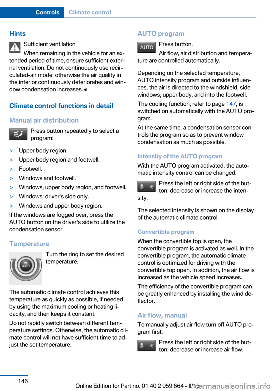
HintsSufficient ventilation
When remaining in the vehicle for an ex‐
tended period of time, ensure sufficient exter‐
nal ventilation. Do not continuously use recir‐
culated-air mode; otherwise the air quality in
the interior continuously deteriorates and win‐
dow condensation increases.◀
Climate control functions in detail
Manual air distribution Press button repeatedly to select a
program:▷Upper body region.▷Upper body region and footwell.▷Footwell.▷Windows and footwell.▷Windows, upper body region, and footwell.▷Windows: driver's side only.▷Windows and upper body region.
If the windows are fogged over, press the
AUTO button on the driver's side to utilize the
condensation sensor.
Temperature Turn the ring to set the desired
temperature.
The automatic climate control achieves this
temperature as quickly as possible, if needed
by using the maximum cooling or heating li‐
dacity, and then keeps it constant.
Do not rapidly switch between different tem‐
perature settings. Otherwise, the automatic cli‐
mate control will not have sufficient time to ad‐
just the set temperature.
AUTO program
Press button.
Air flow, air distribution and tempera‐
ture are controlled automatically.
Depending on the selected temperature,
AUTO intensity program and outside influen‐
ces, the air is directed to the windshield, side
windows, upper body, and into the footwell.
The cooling function, refer to page 147, is
switched on automatically with the AUTO pro‐
gram.
At the same time, a condensation sensor con‐
trols the program so as to prevent window
condensation as much as possible.
Intensity of the AUTO program
With the AUTO program activated, the auto‐
matic intensity control can be changed.
Press the left or right side of the but‐
ton: decrease or increase the inten‐
sity.
The selected intensity is shown on the display
of the automatic climate control.
Convertible program
When the convertible top is open, the
convertible program is activated as well. In the
convertible program, the automatic climate
control is optimized for driving with the
convertible top open. In addition, the air flow is increased as the vehicle speed increases.
The efficiency of the convertible program can
be greatly enhanced by installing the wind de‐
flector.
Air flow, manual To manually adjust air flow turn off AUTO pro‐
gram first.
Press the left or right side of the but‐
ton: decrease or increase air flow.Seite 146ControlsClimate control146
Online Edition for Part no. 01 40 2 959 664 - II/15
Page 151 of 230
The selected air flow is shown on the display of
the automatic climate control.
The air flow of the automatic climate control
may be reduced automatically to save battery
power.
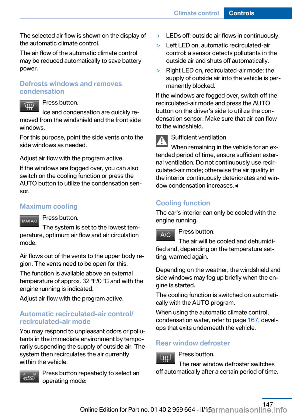
Defrosts windows and removes
condensation
Press button.
Ice and condensation are quickly re‐
moved from the windshield and the front side
windows.
For this purpose, point the side vents onto the
side windows as needed.
Adjust air flow with the program active.
If the windows are fogged over, you can also
switch on the cooling function or press the
AUTO button to utilize the condensation sen‐
sor.
Maximum cooling Press button.
The system is set to the lowest tem‐
perature, optimum air flow and air circulation
mode.
Air flows out of the vents to the upper body re‐
gion. The vents need to be open for this.
The function is available above an external
temperature of approx. 32 ℉/0 ℃ and with the
engine running is indicated.
Adjust air flow with the program active.
Automatic recirculated-air control/recirculated-air mode
You may respond to unpleasant odors or pollu‐
tants in the immediate environment by tempo‐
rarily suspending the supply of outside air. The
system then recirculates the air currently within the vehicle.
Press button repeatedly to select an
operating mode:▷LEDs off: outside air flows in continuously.▷Left LED on, automatic recirculated-air
control: a sensor detects pollutants in the
outside air and shuts off automatically.▷Right LED on, recirculated-air mode: the
supply of outside air into the vehicle is per‐
manently blocked.
If the windows are fogged over, switch off the
recirculated-air mode and press the AUTO
button on the driver's side to utilize the con‐
densation sensor. Make sure that air can flow
to the windshield.
Sufficient ventilation
When remaining in the vehicle for an ex‐
tended period of time, ensure sufficient exter‐
nal ventilation. Do not continuously use recir‐
culated-air mode; otherwise the air quality in
the interior continuously deteriorates and win‐
dow condensation increases.◀
Cooling function The car's interior can only be cooled with the
engine running.
Press button.
The air will be cooled and dehumidi‐
fied and, depending on the temperature set‐
ting, warmed again.
Depending on the weather, the windshield and
side windows may fog up briefly when the en‐
gine is started.
The cooling function is switched on automati‐
cally with the AUTO program.
When using the automatic climate control,
condensation water, refer to page 167, devel‐
ops that exits underneath the vehicle.
Rear window defroster Press button.
The rear window defroster switches
off automatically after a certain period of time.
Seite 147Climate controlControls147
Online Edition for Part no. 01 40 2 959 664 - II/15
Page 197 of 230
MaintenanceVehicle features and options
This chapter describes all standard, country-
specific and optional features offered with the
series. It also describes features that are not
necessarily available in your car, e. g., due to
the selected options or country versions. This
also applies to safety-related functions and
systems. The respectively applicable country
provisions must be observed when using the
respective features and systems.
BMW maintenance system The maintenance system indicates required
maintenance measures, and thereby provides
support in maintaining road safety and the op‐
erational reliability of the vehicle.
In some cases scopes and intervals may vary
according to the country-specific version. Re‐
placement work, spare parts, fuels and lubri‐
cants and wear materials are calculated sepa‐
rately. Additional information is available from
the service center.
Condition Based Service
CBS
Sensors and special algorithms take into ac‐
count the driving conditions of your vehicle.
Based on this, Condition Based Service recog‐
nizes the maintenance requirements.
The system makes it possible to adapt the
amount of maintenance corresponding to your
user profile.
Detailed information on service requirements,
refer to page 91, can be displayed on the Con‐
trol Display.Service data in the remote control
Information on the required maintenance is
continuously stored in the remote control. Your service center will read out this data and
suggest the right array of service procedures for your vehicle.
Therefore, hand your service specialist the re‐
mote control with which the vehicle was driven
most recently.
Storage periods Storage periods during which the vehicle bat‐
tery was disconnected are not taken into ac‐
count.
If this occurs, have a service center update the
time-dependent maintenance procedures,
such as checking brake fluid and, if needed,
changing the engine oil and the microfilter/
activated-charcoal filter.
Service and Warranty
Information Booklet for US
models and Warranty and
Service Guide Booklet for
Canadian models
Please consult your Service and Warranty In‐
formation Booklet for US models and Warranty
and Service Guide Booklet for Canadian mod‐
els for additional information on service re‐
quirements.
Maintenance and repair should be performed
by your service center. Make sure to have reg‐
ular maintenance procedures recorded in the
vehicle's Service and Warranty Information
Booklet for US models, and in the Warranty
and Service Guide Booklet for Canadian mod‐
els. These entries are proof of regular mainte‐
nance.Seite 193MaintenanceMobility193
Online Edition for Part no. 01 40 2 959 664 - II/15
Page 210 of 230
CareVehicle features and optionsThis chapter describes all standard, country-
specific and optional features offered with the
series. It also describes features that are not
necessarily available in your car, e. g., due to
the selected options or country versions. This
also applies to safety-related functions and
systems. The respectively applicable country
provisions must be observed when using the
respective features and systems.
Car washes General information
Regularly remove foreign objects such as
leaves in the area below the windshield when
the hood is raised.
Wash your vehicle frequently, particularly in
winter. Intense soiling and road salt can dam‐
age the vehicle.
Hints Steam jets or high-pressure washers
When using steam jets or high-pressure
washers, hold them a sufficient distance away
and use a maximum temperature of
140 ℉/60 ℃.
Holding them too close or using excessively
high pressures or temperatures can cause
damage or preliminary damage that may then lead to long-term damage.
Follow the user's manual for the high-pressure
washer.◀
Cleaning sensors/camera lenses with
high-pressure washers
When using high-pressure washers, do not
spray the sensors and camera lenses on theoutside of the vehicle for long periods and
maintain a distance of at least 12 in/30 cm.◀
Automatic car washes
Hints Do not use high pressure washing sys‐
tems
With washing systems operating at high pres‐
sures and nozzle positions close to the win‐
dows, drops of water can penetrate.◀
Note the following:▷Give preference to cloth car washes or
those that use soft brushes in order to
avoid paint damage.▷Make sure that the wheels and tires are not
damaged by the transport mechanisms.▷Fold in the exterior mirrors; otherwise, they
may be damaged, depending on the width
of the vehicle.▷Deactivate the rain sensor, refer to
page 76, to avoid unintentional wiper acti‐
vation.▷Do not treat the convertible top with wax.
Ensure that a cycle without wax or a spe‐
cial cycle for convertibles is available.▷In some cases, an unintentional alarm can
be triggered by the interior motion sensor
of the alarm system. Follow the instruc‐
tions on avoiding an unintentional alarm,
refer to page 45.
Guide rails in car washes
Avoid car washes with guide rails higher
than 4 in/10 cm; otherwise, the vehicle body
could be damaged.◀
Before driving into a car wash In order to ensure that the vehicle can roll in a
car wash, take the following steps:
Seite 206MobilityCare206
Online Edition for Part no. 01 40 2 959 664 - II/15
Page 214 of 230
Ensure that the floor mats are securely fas‐
tened again after they were removed for clean‐
ing, e.g.◀
Floor mats can be removed from the car's inte‐
rior for cleaning.
If the floor carpets are very dirty, clean with a
microfiber cloth and water or a textile cleaner.
To prevent matting of the carpet, rub back and
forth in the direction of travel only.
Sensor/camera lenses To clean sensors and camera lenses, use a
cloth moistened with a small amount of glass
detergent.
Displays/monitors Cleaning displays and screens
Do not use any chemical or household
cleaning agents; otherwise, surfaces can be af‐
fected.◀
Keeping out moisture
Keep all fluids and moisture away from
the unit; otherwise, electrical components can
be damaged.◀
Avoid pressure
Avoid pressing too hard when cleaning
and do not use abrasive materials; otherwise,
damage can result.◀
Clean with a clean, antistatic microfiber cloth.
Long-termWhen the vehicle is shut down for longer than
three months, special measures must be
taken. Additional information is available from
the service center.Seite 210MobilityCare210
Online Edition for Part no. 01 40 2 959 664 - II/15
Page 224 of 230
IIce warning, see External temperature warning 89
Icy roads, see External tem‐ perature warning 89
Identification marks, tires 179
Identification number, see ve‐ hicle identification num‐
ber 9
iDrive 18
Ignition key, refer to Remote control 34
Ignition off 69
Ignition on 69
Indication of a flat tire 111 , 113
Indicator and alarm lamps, see Check Control 85
Indicator lamp, see Check Control 85
Individual air distribution 146
Individual settings, refer to M Drive 128
Individual settings, refer to Personal Profile 35
Inflation pressure, tires 178
Inflation pressure warning FTM, tires 112
Info display, refer to On- Board computer 94
Initialize, Tire Pressure Moni‐ tor TPM 111
Initializing, Flat Tire Monitor FTM 113
Instrument cluster 84
Instrument cluster, electronic displays 84
Instrument lighting 104
Integrated key 34
Integrated Owner's Manual in the vehicle 29
Intelligent Emergency Re‐ quest 200
Intelligent Safety 113 Intensity, AUTO pro‐
gram 146
Interior equipment 150
Interior lights 104
Interior lights during unlock‐ ing 37
Interior lights with the vehicle locked 38
Interior motion sensor 45
Interior rearview mirror, auto‐ matic dimming feature 64
Internet page 6
Interval display, service re‐ quirements 91
Interval mode 76
J
Jacking points for the vehicle jack 198
Jump-starting 202
K
Key/remote control 34
Keyless Go, refer to Comfort Access 42
Key Memory, refer to Per‐ sonal Profile 35
Knee airbag 106
L Lamp replacement, front 195
Lamp replacement, rear 197
Lane departure warning 123
Lane margin, warning 123
Language on Control Dis‐ play 98
Lashing eyes, securing cargo 169
LATCH child restraint sys‐ tem 68
Launch Control 81
Leather, care 208 LED headlights, bulb replace‐
ment 196
LED light 196
LEDs, light-emitting di‐ odes 196
Length, vehicle 214
Letters and numbers, enter‐ ing 24
License plate lamp, bulb re‐ placement 197
Light alloy wheels, care 209
Light control 102
Light-emitting diodes, LEDs 196
Lighting 101
Lighting, speaker 105
Lights 101
Lights and bulbs 195
Light switch 101
Load 169
Loading 168
Lock, door 40
Locking/unlocking via door lock 40
Locking/unlocking with re‐ mote control 37
Locking, automatic 44
Locking, settings 43
Locking via trunk lid 41
Low beams 101
Low beams, automatic, refer to High-beam Assistant 103
Lower back support 57
Low Speed Assistant 79
Lumbar support 57
M
Maintenance 193
Maintenance require‐ ments 193
Maintenance, service require‐ ments 91
Maintenance system, BMW 193
Make-up mirror 152 Seite 220ReferenceEverything from A to Z220
Online Edition for Part no. 01 40 2 959 664 - II/15