remote control BMW M6 COUPE 2013 F13 Owner's Guide
[x] Cancel search | Manufacturer: BMW, Model Year: 2013, Model line: M6 COUPE, Model: BMW M6 COUPE 2013 F13Pages: 214, PDF Size: 7.08 MB
Page 132 of 214
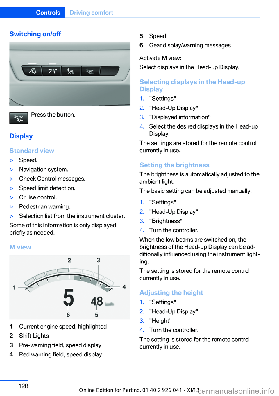
Switching on/off
Press the button.
Display
Standard view
▷Speed.▷Navigation system.▷Check Control messages.▷Speed limit detection.▷Cruise control.▷Pedestrian warning.▷Selection list from the instrument cluster.
Some of this information is only displayed
briefly as needed.
M view
1Current engine speed, highlighted2Shift Lights3Pre-warning field, speed display4Red warning field, speed display5Speed6Gear display/warning messages
Activate M view:
Select displays in the Head-up Display.
Selecting displays in the Head-up
Display
1."Settings"2."Head-Up Display"3."Displayed information"4.Select the desired displays in the Head-up
Display.
The settings are stored for the remote control
currently in use.
Setting the brightness
The brightness is automatically adjusted to the
ambient light.
The basic setting can be adjusted manually.
1."Settings"2."Head-Up Display"3."Brightness"4.Turn the controller.
When the low beams are switched on, the
brightness of the Head-up Display can be ad‐
ditionally influenced using the instrument light‐
ing.
The setting is stored for the remote control
currently in use.
Adjusting the height
1."Settings"2."Head-Up Display"3."Height"4.Turn the controller.
The setting is stored for the remote control
currently in use.
Seite 128ControlsDriving comfort128
Online Edition for Part no. 01 40 2 910 796 - VI/13
Page 133 of 214
Setting the rotation1."Settings"2."Head-Up Display"3."Rotation"4.Turn the controller.
The setting is stored for the remote control
currently in use.
Special windshield
The windshield is part of the system.
The shape of the windshield makes it possible
to display a precise image.
A film in the windshield prevents double im‐
ages from being displayed.
Therefore, have the special windshield re‐
placed by a service center only.
Seite 129Driving comfortControls129
Online Edition for Part no. 01 40 2 910 796 - VI/13
Page 139 of 214
Interior equipmentVehicle equipmentAll standard, country-specific and optional
equipment that is offered in the model series is
described in this chapter. Therefore, equip‐
ment is also described that is not available in a
vehicle, e. g., because of the selected optional
equipment or country variant. This also applies
for safety-related functions and systems.
Integrated universal remote
control
The conceptThe integrated universal remote control can
operate up to 3 functions of remote-controlled
systems such as garage door drives or lighting
systems. The integrated universal remote con‐
trol replaces up to 3 different hand-held trans‐
mitters. To operate the remote control, the
buttons on the interior rearview mirror must be
programmed with the desired functions. The
hand-held transmitter for the particular system
is required in order to program the remote con‐
trol.
During programming
During programming and before activat‐
ing a device using the integrated universal re‐
mote control, ensure that there are no people,
animals, or objects in the range of movement
of the remote-controlled device; otherwise,
there is a risk of injury or damage.
Also follow the safety instructions of the hand-
held transmitter.◀
Before selling the vehicle, delete the stored
functions for the sake of security.Compatibility
If this symbol is printed on the packag‐
ing or in the instructions of the system
to be controlled, the system is gener‐
ally compatible with the integrated universal
remote control.
If you have any questions, please contact:▷Your service center.▷www.homelink.com on the Internet.
HomeLink is a registered trademark of John‐
son Controls, Inc.
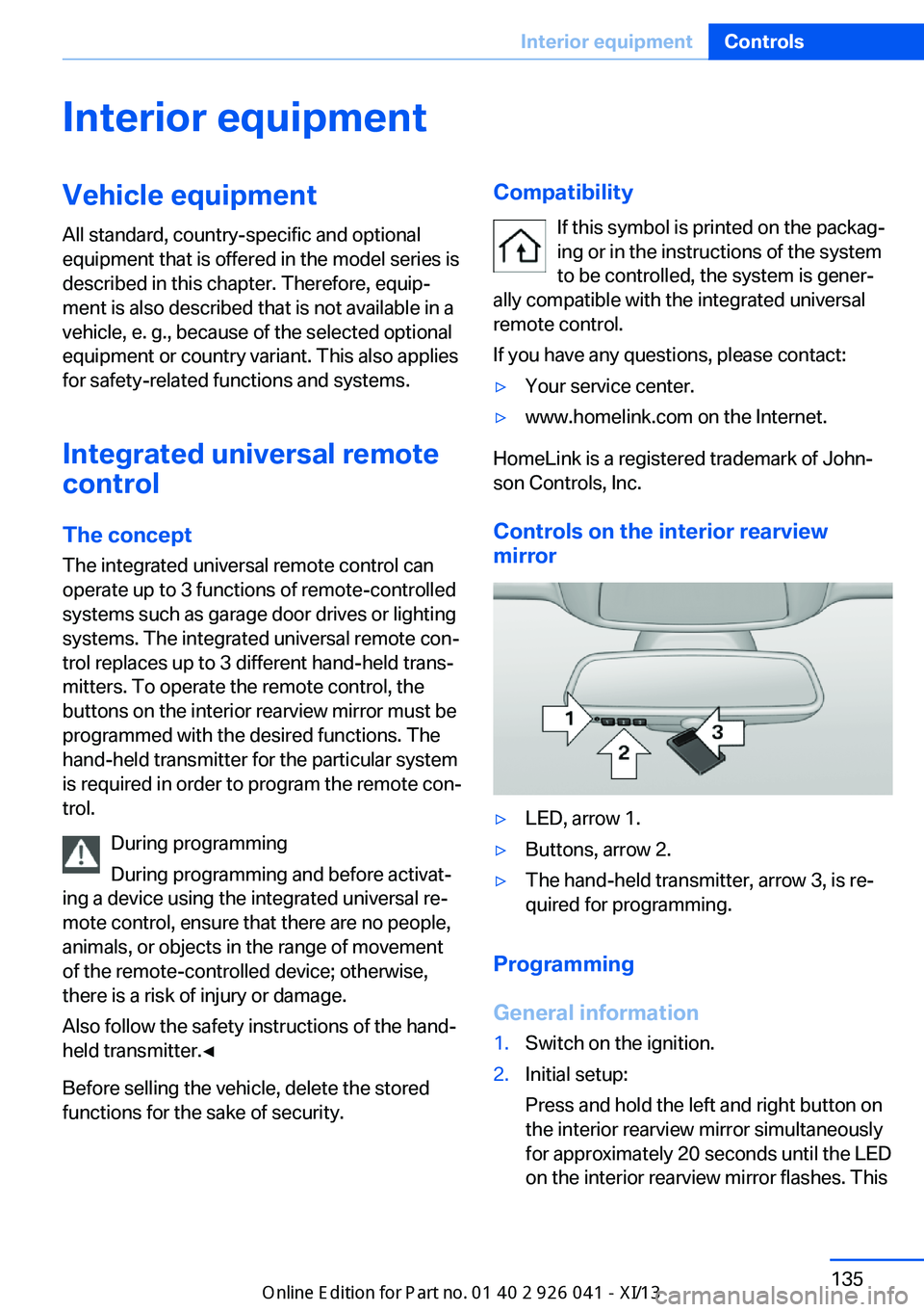
Controls on the interior rearview
mirror
▷LED, arrow 1.▷Buttons, arrow 2.▷The hand-held transmitter, arrow 3, is re‐
quired for programming.
Programming
General information
1.Switch on the ignition.2.Initial setup:
Press and hold the left and right button on
the interior rearview mirror simultaneously
for approximately 20 seconds until the LED
on the interior rearview mirror flashes. ThisSeite 135Interior equipmentControls135
Online Edition for Part no. 01 40 2 910 796 - VI/13
Page 140 of 214
erases all programming of the buttons on
the interior rearview mirror.3.Hold the hand-held transmitter for the sys‐
tem to be controlled approx. 1 to 3 in/2.5 to
8 cm away from the buttons on the interior
rearview mirror. The required distance de‐
pends on the manual transmitter.4.Simultaneously press and hold the button
of the desired function on the hand-held
transmitter and the button to be program‐
med on the interior rearview mirror. The
LED on the interior rearview mirror will be‐
gin flashing slowly.5.Release both buttons as soon as the LED
flashes more rapidly. When the LED is
flashing faster, this indicates that the but‐
ton on the interior rearview mirror has been
programmed.
If the LED does not flash faster after at
least 60 seconds, change the distance be‐
tween the interior rearview mirror and the
hand-held transmitter and repeat the step.
Several more attempts at different distan‐
ces may be necessary. Wait at least
15 seconds between attempts.
Canada: if programming with the hand-
held transmitter was interrupted, hold
down the interior rearview mirror button
and repeatedly press and release the
hand-held transmitter button for 2 sec‐
onds.6.To program other functions on other but‐
tons, repeat steps 3 to 5.
The systems can be controlled using the inte‐
rior rearview mirror buttons.
Special feature of the alternating-
code wireless system
If you are unable to operate the system after
repeated programming, please check if the
system to be controlled features an alternat‐
ing-code system.
Read the system's operating manual, or press
the programmed button on the interior rear‐
view mirror longer. If the LED on the interior
rearview mirror starts flashing rapidly and then
stays lit constantly for 2 seconds, the system
features an alternating-code system. Flashing
and continuous illumination of the LED will re‐
peat for approximately 20 seconds.
For systems with an alternating-code system,
the integrated universal remote control and the
system also have to be synchronized.
Please read the operating manual of the sys‐
tem being set up for information on how to
synchronize the system.
Synchronizing is easier with the aid of a sec‐
ond person.
To synchronize:1.Park the vehicle within range of the re‐
mote-controlled system.2.Program the relevant button on the interior
rearview mirror as described.3.Locate and press the synchronizing button
on the system being programmed. You
have approx. 30 seconds for the next step.4.Hold down the programmed button on the
interior rearview mirror for approximately
3 seconds and then release it. If necessary,
repeat this work step up to three times in
order to finish synchronization. Once syn‐
chronization is complete, the programmed
function will be carried out.
Reprogramming individual buttons
1.Switch on the ignition.2.Press and hold the interior rearview mirror
button to be programmed.3.As soon as the interior rearview mirror LED
starts flashing slowly, hold the hand-held
transmitter for the system to be controlled
approx. 1 to 3 in/2.5 to 8 cm away from the
buttons on the interior rearview mirror. The
required distance depends on the manual
transmitter.Seite 136ControlsInterior equipment136
Online Edition for Part no. 01 40 2 910 796 - VI/13
Page 141 of 214
4.Likewise, press and hold the button of the
desired function on the hand-held trans‐
mitter.5.Release both buttons as soon as the inte‐
rior rearview mirror LED flashes more rap‐
idly. When the LED is flashing faster, this
indicates that the button on the interior
rearview mirror has been programmed.
The system can then be controlled by the
button on the interior rearview mirror.
If the LED does not flash faster after at
least 60 seconds, change the distance and
repeat the step. Several more attempts at
different distances may be necessary. Wait
at least 15 seconds between attempts.
Canada: if programming with the hand-
held transmitter was interrupted, hold
down the interior rearview mirror button
and repeatedly press and release the
hand-held transmitter button for 2 sec‐
onds.
Controls
Before operation
Before operating a system using the
integrated universal remote control, ensure
that there are no people, animals, or objects
within the range of movement of the remote- controlled system; otherwise, there is a risk of
injury or damage.
Also follow the safety instructions of the hand-
held transmitter.◀
The system, such as the garage door, can be
operated using the button on the interior rear‐
view mirror while the engine is running or when
the ignition is started. To do this, hold down
the button within receiving range of the system
until the function is activated. The interior rear‐ view mirror LED stays lit while the wireless sig‐
nal is being transmitted.
Deleting stored functions Press and hold the left and right button on the
interior rearview mirror simultaneously for ap‐
proximately 20 seconds until the LED flashes
rapidly. All stored functions are deleted. The
functions cannot be deleted individually.
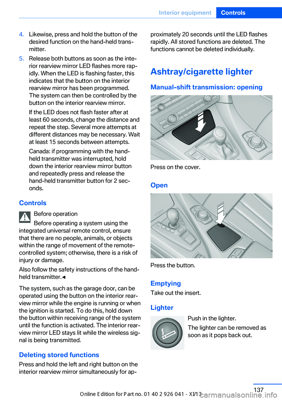
Ashtray/cigarette lighter Manual-shift transmission: opening
Press on the cover.
Open
Press the button. Emptying
Take out the insert.
Lighter Push in the lighter.
The lighter can be removed as
soon as it pops back out.
Seite 137Interior equipmentControls137
Online Edition for Part no. 01 40 2 910 796 - VI/13
Page 142 of 214
Danger of burns
Only hold the hot lighter by its knob; oth‐
erwise, there is the danger of getting burned.
Switch off the ignition and take the remote
control with you when leaving the vehicle so
that children cannot use the lighter and burn
themselves.◀
Replace the cover after use
Reinsert the lighter or socket cover after
use, otherwise objects may get into the lighter
socket or fixture and cause a short circuit.◀
Connecting electrical
devices
Hints Do not plug chargers into the socketDo not connect battery chargers to the
factory-installed sockets in the vehicle as this
may damage the battery.◀
Replace the cover after use
Reinsert the lighter or socket cover after
use, otherwise objects may get into the lighter
socket or fixture and cause a short circuit.◀
Sockets
The lighter socket can be used as a socket for
electrical equipment while the engine is run‐
ning or when the ignition is switched on. The
total load of all sockets must not exceed
140 watts at 12 volts.
Do not damage the socket by using unsuitable
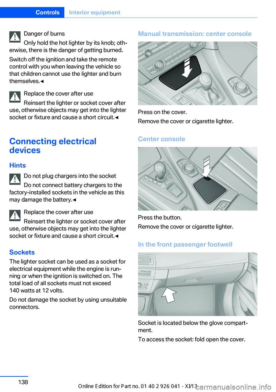
connectors.Manual transmission: center console
Press on the cover.
Remove the cover or cigarette lighter.
Center console
Press the button.
Remove the cover or cigarette lighter.
In the front passenger footwell
Socket is located below the glove compart‐
ment.
To access the socket: fold open the cover.
Seite 138ControlsInterior equipment138
Online Edition for Part no. 01 40 2 910 796 - VI/13
Page 145 of 214
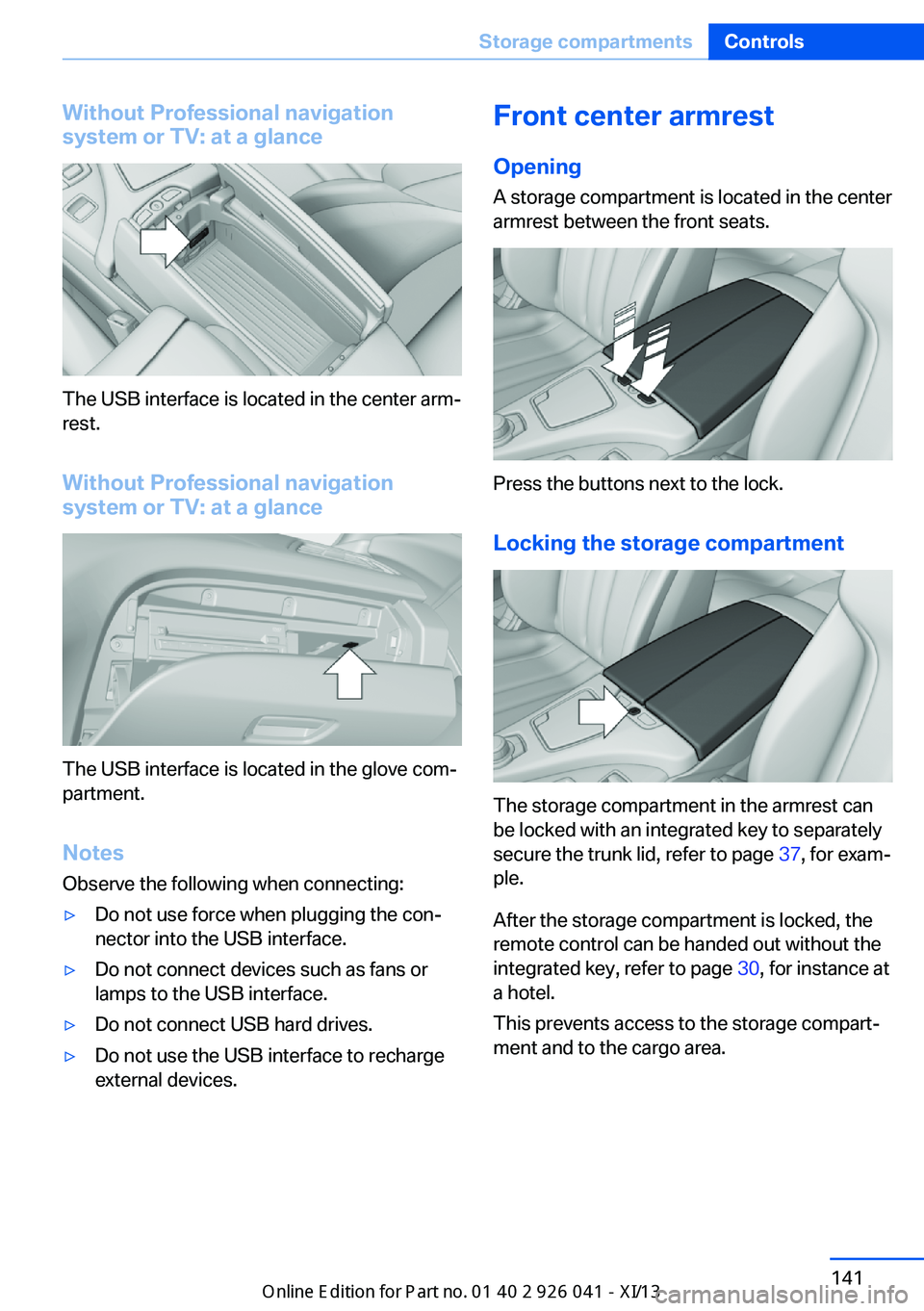
Without Professional navigation
system or TV: at a glance
The USB interface is located in the center arm‐
rest.
Without Professional navigation
system or TV: at a glance
The USB interface is located in the glove com‐
partment.
Notes
Observe the following when connecting:
▷Do not use force when plugging the con‐
nector into the USB interface.▷Do not connect devices such as fans or
lamps to the USB interface.▷Do not connect USB hard drives.▷Do not use the USB interface to recharge
external devices.Front center armrest
Opening A storage compartment is located in the center
armrest between the front seats.
Press the buttons next to the lock.
Locking the storage compartment
The storage compartment in the armrest can
be locked with an integrated key to separately
secure the trunk lid, refer to page 37, for exam‐
ple.
After the storage compartment is locked, the
remote control can be handed out without the
integrated key, refer to page 30, for instance at
a hotel.
This prevents access to the storage compart‐
ment and to the cargo area.
Seite 141Storage compartmentsControls141
Online Edition for Part no. 01 40 2 910 796 - VI/13
Page 180 of 214
MaintenanceVehicle equipment
All standard, country-specific and optional
equipment that is offered in the model series is
described in this chapter. Therefore, equip‐
ment is also described that is not available in a
vehicle, e. g., because of the selected optional
equipment or country variant. This also applies
for safety-related functions and systems.
BMW Maintenance System The maintenance system directs you to re‐
quired maintenance measures and thereby
supports you in maintaining road safety and
the operational reliability of the vehicle.
Condition Based Service
CBS
Sensors and special algorithms take into ac‐
count the driving conditions of your vehicle.
Based on this, Condition Based Service deter‐
mines the maintenance requirements.
The system makes it possible to adapt the
amount of maintenance you need to your user
profile.
Details on the service requirements, refer to
page 80, can be displayed on the Control Dis‐
play.
Service data in the remote control
Information on the required maintenance is
continuously stored in the remote control.
Your service center will read out this data and
suggest the right array of service procedures
for your vehicle.
Therefore, hand your service specialist the re‐
mote control with which the vehicle was driven
most recently.Storage periods
Storage periods during which the vehicle bat‐
tery was disconnected are not taken into ac‐
count.
If this occurs, have a service center update the
time-dependent maintenance procedures,
such as checking brake fluid and, if necessary,
changing the engine oil and the microfilter/
activated-charcoal filter.
Service booklet Perform maintenance work at the service cen‐
ter, and record the work in the service booklet.
The entries are proof of regular maintenance.
Service and Warranty
Information Booklet for US
models and Warranty and
Service Guide Booklet for
Canadian models
Please consult your Service and Warranty In‐
formation Booklet for US models and Warranty
and Service Guide Booklet for Canadian mod‐
els for additional information on service re‐
quirements.
Maintenance and repair should be performed
by your service center. Make sure to have reg‐
ular maintenance procedures recorded in the
vehicle's Service and Warranty Information
Booklet for US models, and in the Warranty
and Service Guide Booklet for Canadian mod‐
els. These entries are proof of regular mainte‐
nance.Seite 176MobilityMaintenance176
Online Edition for Part no. 01 40 2 910 796 - VI/13
Page 204 of 214
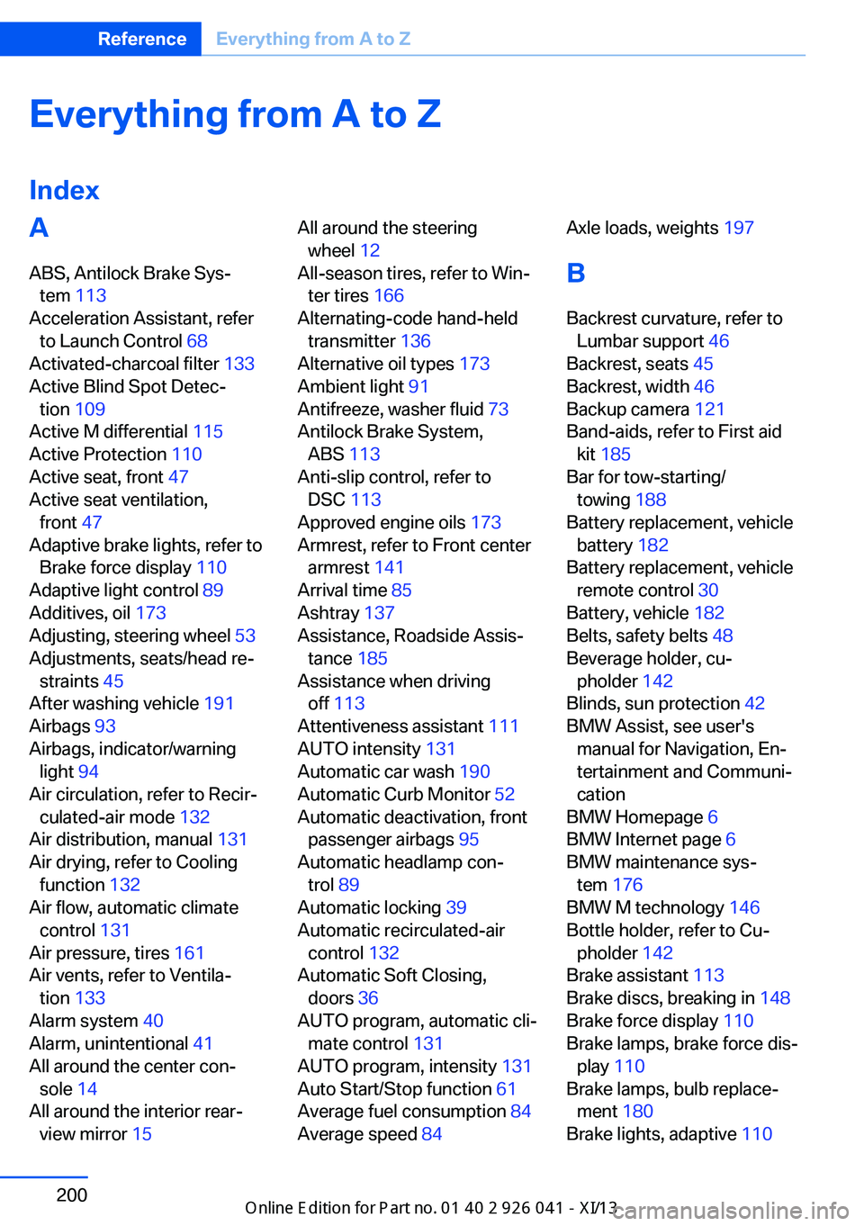
Everything from A to Z
IndexA ABS, Antilock Brake Sys‐ tem 113
Acceleration Assistant, refer to Launch Control 68
Activated-charcoal filter 133
Active Blind Spot Detec‐ tion 109
Active M differential 115
Active Protection 110
Active seat, front 47
Active seat ventilation, front 47
Adaptive brake lights, refer to Brake force display 110
Adaptive light control 89
Additives, oil 173
Adjusting, steering wheel 53
Adjustments, seats/head re‐ straints 45
After washing vehicle 191
Airbags 93
Airbags, indicator/warning light 94
Air circulation, refer to Recir‐ culated-air mode 132
Air distribution, manual 131
Air drying, refer to Cooling function 132
Air flow, automatic climate control 131
Air pressure, tires 161
Air vents, refer to Ventila‐ tion 133
Alarm system 40
Alarm, unintentional 41
All around the center con‐ sole 14
All around the interior rear‐ view mirror 15 All around the steering
wheel 12
All-season tires, refer to Win‐ ter tires 166
Alternating-code hand-held transmitter 136
Alternative oil types 173
Ambient light 91
Antifreeze, washer fluid 73
Antilock Brake System, ABS 113
Anti-slip control, refer to DSC 113
Approved engine oils 173
Armrest, refer to Front center armrest 141
Arrival time 85
Ashtray 137
Assistance, Roadside Assis‐ tance 185
Assistance when driving off 113
Attentiveness assistant 111
AUTO intensity 131
Automatic car wash 190
Automatic Curb Monitor 52
Automatic deactivation, front passenger airbags 95
Automatic headlamp con‐ trol 89
Automatic locking 39
Automatic recirculated-air control 132
Automatic Soft Closing, doors 36
AUTO program, automatic cli‐ mate control 131
AUTO program, intensity 131
Auto Start/Stop function 61
Average fuel consumption 84
Average speed 84 Axle loads, weights 197
B Backrest curvature, refer to Lumbar support 46
Backrest, seats 45
Backrest, width 46
Backup camera 121
Band-aids, refer to First aid kit 185
Bar for tow-starting/ towing 188
Battery replacement, vehicle battery 182
Battery replacement, vehicle remote control 30
Battery, vehicle 182
Belts, safety belts 48
Beverage holder, cu‐ pholder 142
Blinds, sun protection 42
BMW Assist, see user's manual for Navigation, En‐
tertainment and Communi‐
cation
BMW Homepage 6
BMW Internet page 6
BMW maintenance sys‐ tem 176
BMW M technology 146
Bottle holder, refer to Cu‐ pholder 142
Brake assistant 113
Brake discs, breaking in 148
Brake force display 110
Brake lamps, brake force dis‐ play 110
Brake lamps, bulb replace‐ ment 180
Brake lights, adaptive 110 Seite 200ReferenceEverything from A to Z200
Online Edition for Part no. 01 40 2 910 796 - VI/13
Page 205 of 214
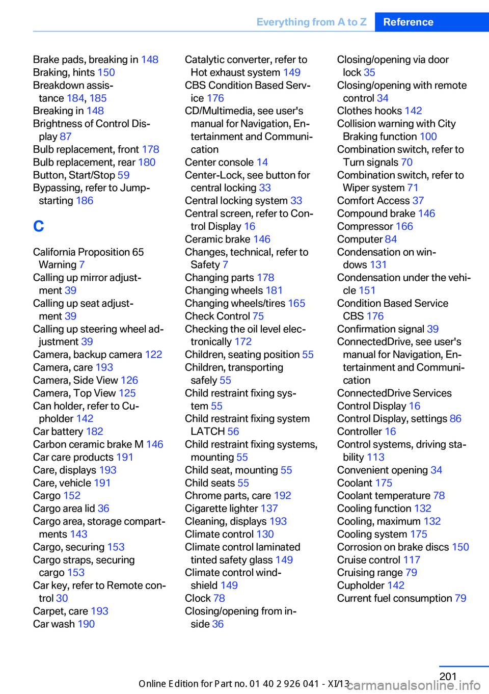
Brake pads, breaking in 148
Braking, hints 150
Breakdown assis‐ tance 184, 185
Breaking in 148
Brightness of Control Dis‐ play 87
Bulb replacement, front 178
Bulb replacement, rear 180
Button, Start/Stop 59
Bypassing, refer to Jump- starting 186
C
California Proposition 65 Warning 7
Calling up mirror adjust‐ ment 39
Calling up seat adjust‐ ment 39
Calling up steering wheel ad‐ justment 39
Camera, backup camera 122
Camera, care 193
Camera, Side View 126
Camera, Top View 125
Can holder, refer to Cu‐ pholder 142
Car battery 182
Carbon ceramic brake M 146
Car care products 191
Care, displays 193
Care, vehicle 191
Cargo 152
Cargo area lid 36
Cargo area, storage compart‐ ments 143
Cargo, securing 153
Cargo straps, securing cargo 153
Car key, refer to Remote con‐ trol 30
Carpet, care 193
Car wash 190 Catalytic converter, refer to
Hot exhaust system 149
CBS Condition Based Serv‐ ice 176
CD/Multimedia, see user's manual for Navigation, En‐
tertainment and Communi‐
cation
Center console 14
Center-Lock, see button for central locking 33
Central locking system 33
Central screen, refer to Con‐ trol Display 16
Ceramic brake 146
Changes, technical, refer to Safety 7
Changing parts 178
Changing wheels 181
Changing wheels/tires 165
Check Control 75
Checking the oil level elec‐ tronically 172
Children, seating position 55
Children, transporting safely 55
Child restraint fixing sys‐ tem 55
Child restraint fixing system LATCH 56
Child restraint fixing systems, mounting 55
Child seat, mounting 55
Child seats 55
Chrome parts, care 192
Cigarette lighter 137
Cleaning, displays 193
Climate control 130
Climate control laminated tinted safety glass 149
Climate control wind‐ shield 149
Clock 78
Closing/opening from in‐ side 36 Closing/opening via door
lock 35
Closing/opening with remote control 34
Clothes hooks 142
Collision warning with City Braking function 100
Combination switch, refer to Turn signals 70
Combination switch, refer to Wiper system 71
Comfort Access 37
Compound brake 146
Compressor 166
Computer 84
Condensation on win‐ dows 131
Condensation under the vehi‐ cle 151
Condition Based Service CBS 176
Confirmation signal 39
ConnectedDrive, see user's manual for Navigation, En‐
tertainment and Communi‐
cation
ConnectedDrive Services
Control Display 16
Control Display, settings 86
Controller 16
Control systems, driving sta‐ bility 113
Convenient opening 34
Coolant 175
Coolant temperature 78
Cooling function 132
Cooling, maximum 132
Cooling system 175
Corrosion on brake discs 150
Cruise control 117
Cruising range 79
Cupholder 142
Current fuel consumption 79 Seite 201Everything from A to ZReference201
Online Edition for Part no. 01 40 2 910 796 - VI/13