lights BMW M6 COUPE 2013 F13 Owner's Manual
[x] Cancel search | Manufacturer: BMW, Model Year: 2013, Model line: M6 COUPE, Model: BMW M6 COUPE 2013 F13Pages: 214, PDF Size: 7.08 MB
Page 12 of 214
▷New Vehicle Limited Warranty.▷Rust Perforation Limited Warranty.▷Federal Emissions System Defect War‐
ranty.▷Federal Emissions Performance Warranty.▷California Emission Control System Lim‐
ited Warranty.
Detailed information about these warranties is
listed in the Service and Warranty Information
Booklet for US models or in the Warranty and
Service Guide Booklet for Canadian models.
Your vehicle has been specifically adapted and
designed to meet the particular operating con‐
ditions and homologation requirements in your
country and continental region in order to de‐
liver the full driving pleasure while the vehicle
is operated under those conditions. If you wish
to operate your vehicle in another country or
region, you may be required to adapt your ve‐
hicle to meet different prevailing operating
conditions and homologation requirements.
You should also be aware of any applicable
warranty limitations or exclusions for such
country or region. In such case, please contact
Customer Relations for further information.
Maintenance
Maintain the vehicle regularly to sustain the
road safety, operational reliability and the New
Vehicle Limited Warranty.
Specifications for required maintenance meas‐
ures:
в–·BMW Maintenance systemв–·Service and Warranty Information Booklet
for US modelsв–·Warranty and Service Guide Booklet for
Canadian models
If the vehicle is not maintained according to
these specifications, this could result in seri‐
ous damage to the vehicle. Such damage is
not covered by the BMW New Vehicle Limited
Warranty.
Data memory
Many electronic components on your vehicle
are equipped with data memories that tempo‐
rarily or permanently store technical informa‐
tion about the condition of the vehicle, events
and faults. This technical information generally
documents the state of a component, a mod‐
ule, a system or the environment:в–·Operating states of system components,
fill levels for instance.в–·Status messages for the vehicle and from
its individual components, e.g., wheel rota‐
tion speed/ vehicle speed, deceleration,
transverse acceleration.▷Malfunctions and faults in important sys‐
tem components, e.g., lights and brakes.▷Responses by the vehicle to special situa‐
tions, e.g., deployment of an airbag, en‐
gagement of stability control systems.в–·Ambient conditions, such as temperature.
This data is purely technical in nature and is
used to detect and correct faults and to opti‐
mize vehicle functions. Motion profiles over
routes traveled cannot be created from this
data. When service offerings are used, e.g., re‐
pair services, service processes, warranty
claims, quality assurance, this technical infor‐
mation can be read out from the event and
fault memories by the service personnel, in‐
cluding the manufacturer, using special diag‐
nostic tools. You can obtain further information
there if it is needed. After a fault is corrected,
the information in the fault memory is deleted
or overwritten on a continuous basis.
When the vehicle is in use, situations are con‐
ceivable in which it might be possible to asso‐
ciate this technical data with individuals if it is
combined with other information, e.g., an acci‐
dent report, damage to the vehicle, eye wit‐
ness accounts — possibly with the assistance
of an expert.
Additional functions that are contractually
agreed with the customer, such as vehicle lo‐
Seite 8Notes8
Online Edition for Part no. 01 40 2 910 796 - VI/13
Page 17 of 214
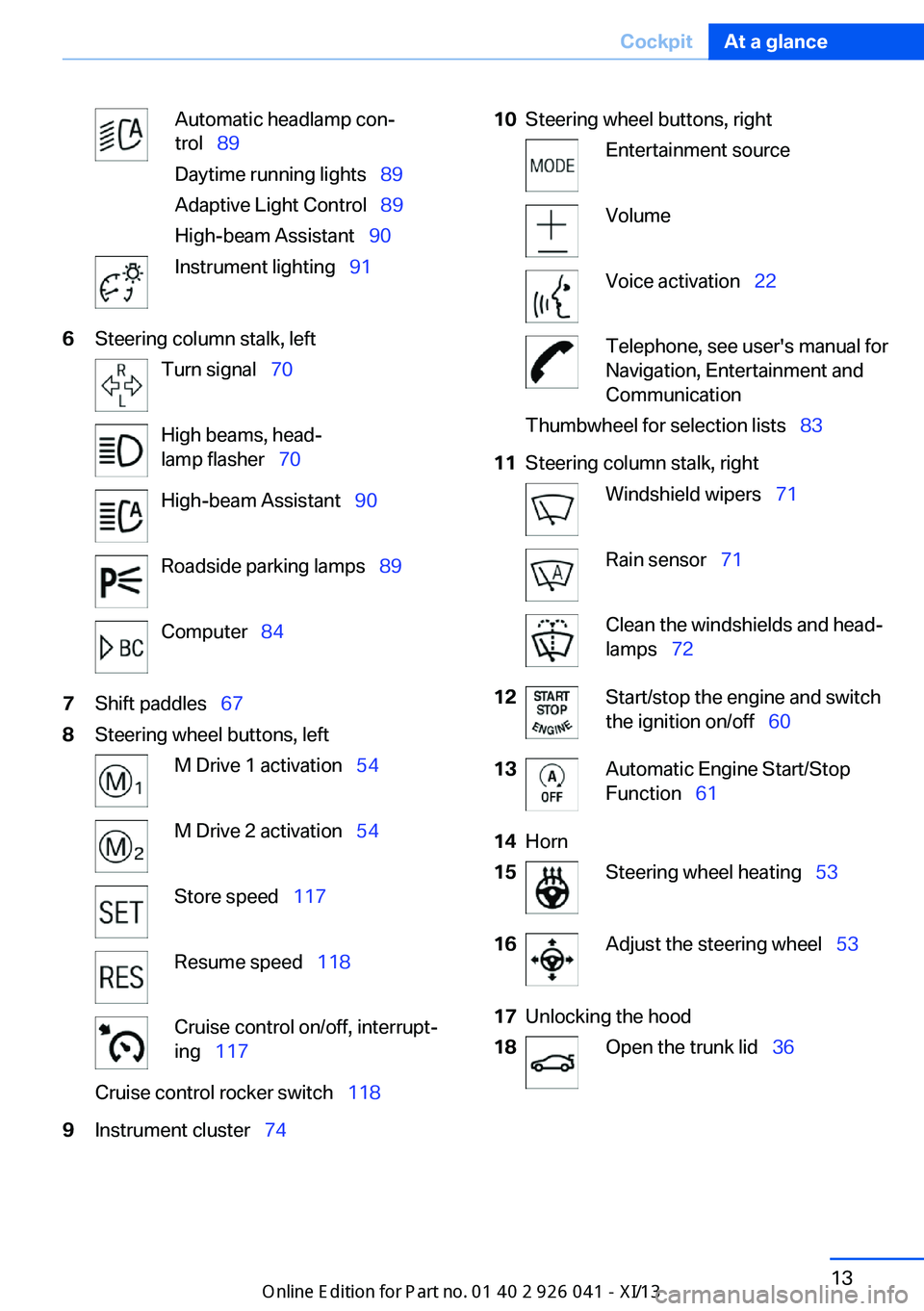
Automatic headlamp con‐
trol   89
Daytime running lights   89
Adaptive Light Control   89
High-beam Assistant   90Instrument lighting  916Steering column stalk, leftTurn signal  70High beams, head‐
lamp flasher   70High-beam Assistant   90Roadside parking lamps   89Computer  847Shift paddles   678Steering wheel buttons, leftM Drive 1 activation   54M Drive 2 activation  54Store speed  117Resume speed   118Cruise control on/off, interrupt‐
ing   117Cruise control rocker switch   1189Instrument cluster  7410Steering wheel buttons, rightEntertainment sourceVolumeVoice activation  22Telephone, see user's manual for
Navigation, Entertainment and
CommunicationThumbwheel for selection lists   8311Steering column stalk, rightWindshield wipers  71Rain sensor  71Clean the windshields and head‐
lamps   7212Start/stop the engine and switch
the ignition on/off   6013Automatic Engine Start/Stop
Function   6114Horn15Steering wheel heating   5316Adjust the steering wheel   5317Unlocking the hood18Open the trunk lid  36Seite 13CockpitAt a glance13
Online Edition for Part no. 01 40 2 910 796 - VI/13
Page 37 of 214
в–·Exterior mirror position.в–·CD/Multimedia: audio source listened to
last.в–·Unlocking/locking of the vehicle: settings.в–·Driver's seat position: automatic retrieval
after unlocking.▷Programmable memory buttons: assign‐
ment.в–·Head-up Display: selection, brightness,
position and rotation of the display.▷Headlamp courtesy delay feature: time set‐
ting.в–·Tone: tone settings.в–·Automatic climate control: settings.в–·Steering wheel position.в–·M Drive: configurations.в–·Navigation: map views, route criteria, voice
output on/off.в–·Night Vision with pedestrian detection.в–·Intelligent Safety: individual settings.в–·Park Distance Control PDC: adjusting the
signal tone volume.в–·Radio: stored stations, station listened to
last, special settings.в–·Rearview camera: selection of functions
and type of display.в–·Side View: selection of the display type.в–·Language on the Control Display.в–·Lane departure warning: last setting, on/
off.в–·Active Blind Spot Detection: last setting,
on/off.в–·Daytime running lights: current setting.в–·Triple turn signal activation.в–·Locking the vehicle: after a brief period or
after starting to drive.Central locking system
The concept The central locking system becomes active
when the driver's door is closed.
The system simultaneously engages and re‐
leases the locks on the following:в–·Doors.в–·Trunk lid.в–·Fuel filler flap.
Operating from the outside
в–·Via the remote control.в–·Via the driver's door lock.в–·Via the door handles.в–·Via the button in the trunk lid.
The following takes place simultaneously
when locking/unlocking the vehicle via the re‐
mote control:
в–·Depending on how the vehicle is equipped,
the theft protection is activated/deacti‐
vated. Theft protection prevents the doors
from being unlocked using the lock but‐
tons or the door opener.в–·The welcome lamps, interior lamps and
courtesy lamps are switched on and off.в–·The alarm system, refer to page 40, is
armed or disarmed.
Operating from the inside
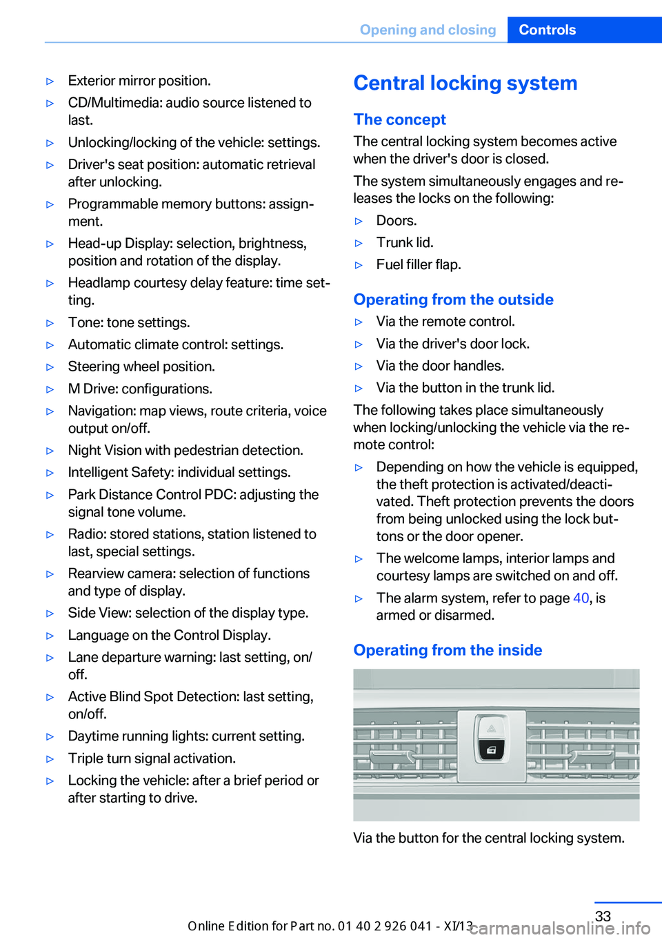
Via the button for the central locking system.
Seite 33Opening and closingControls33
Online Edition for Part no. 01 40 2 910 796 - VI/13
Page 45 of 214
After 10 seconds, the indicator lamp
flashes continuously. Interior motion sen‐
sor and tilt alarm sensor are not active.▷The indicator lamp goes out after unlock‐
ing:
The vehicle has not been tampered with.в–·The indicator lamp flashes after unlocking
until the engine ignition is switched on, but
no longer than approx. 5 minutes:
An alarm has been triggered.
Tilt alarm sensor The tilt of the vehicle is monitored.
The alarm system responds in situations such
as attempts to steal a wheel or when the car is
towed.
Interior motion sensor The windows and glass sunroof must be
closed for the system to function properly.
Avoiding unintentional alarms The tilt alarm sensor and interior motion sen‐
sor can be switched off together, such as in
the following situations:
в–·In automatic car washes.в–·In duplex garages.в–·During transport on car-carrying trains, at
sea or on a trailer.в–·When animals are to remain in the vehicle.
Switching off the tilt alarm sensor and
interior motion sensor
Press the remote control button again
within 10 seconds as soon as the vehicle
is locked.
The indicator lamp lights up for approx. 2 sec‐
onds and then continues to flash.
The tilt alarm sensor and interior motion sen‐
sor are switched off until the vehicle is locked
again.
Power windows
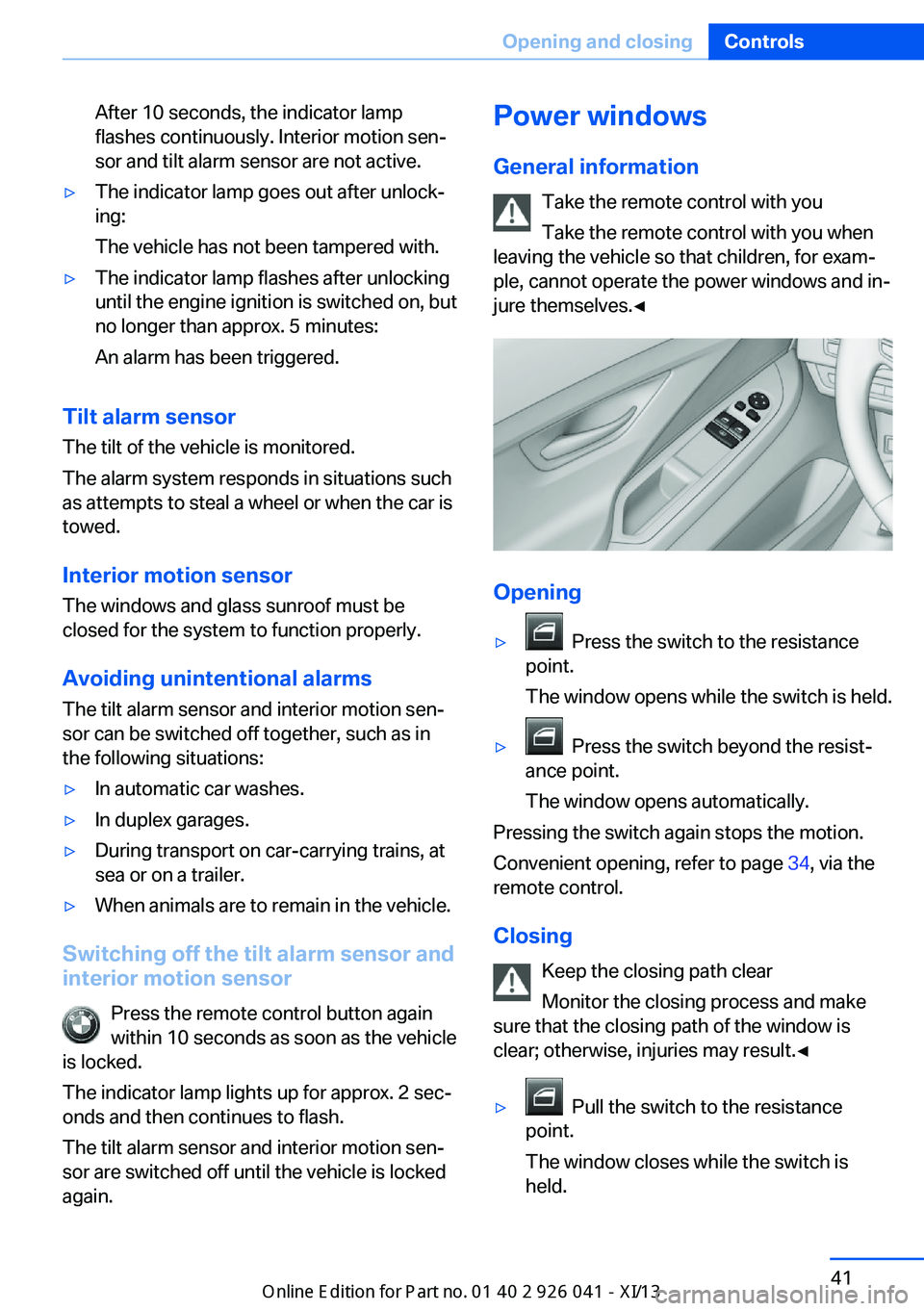
General information Take the remote control with you
Take the remote control with you when
leaving the vehicle so that children, for exam‐
ple, cannot operate the power windows and in‐
jure themselves.в—Ђ
Opening
в–· Press the switch to the resistance
point.
The window opens while the switch is held.▷ Press the switch beyond the resist‐
ance point.
The window opens automatically.
Pressing the switch again stops the motion.
Convenient opening, refer to page 34, via the
remote control.
Closing Keep the closing path clear
Monitor the closing process and make
sure that the closing path of the window is
clear; otherwise, injuries may result.в—Ђ
в–· Pull the switch to the resistance
point.
The window closes while the switch is
held.
Seite 41Opening and closingControls41
Online Edition for Part no. 01 40 2 910 796 - VI/13
Page 51 of 214
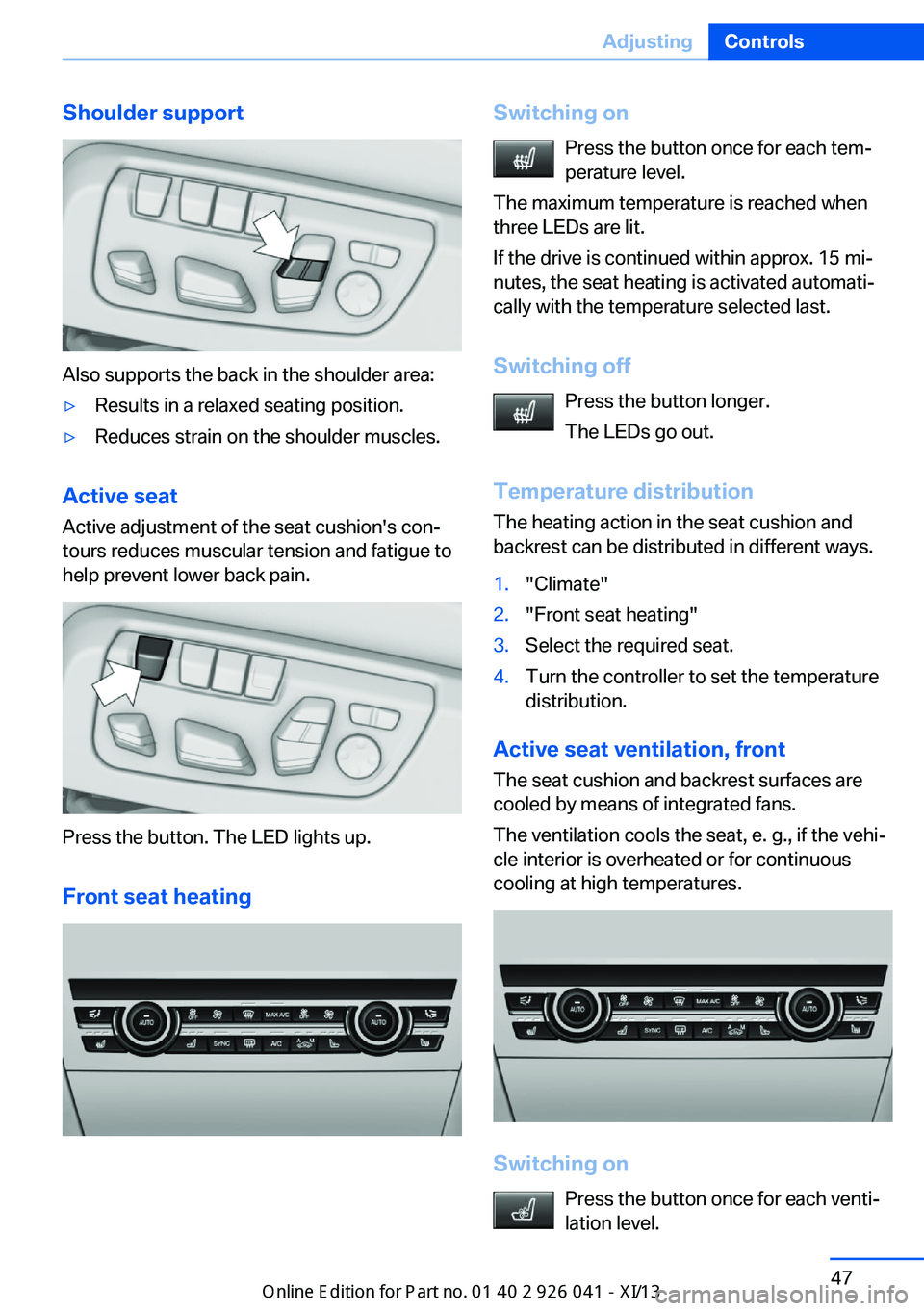
Shoulder support
Also supports the back in the shoulder area:
в–·Results in a relaxed seating position.в–·Reduces strain on the shoulder muscles.
Active seatActive adjustment of the seat cushion's con‐
tours reduces muscular tension and fatigue to
help prevent lower back pain.
Press the button. The LED lights up.
Front seat heating
Switching on Press the button once for each tem‐
perature level.
The maximum temperature is reached when
three LEDs are lit.
If the drive is continued within approx. 15 mi‐
nutes, the seat heating is activated automati‐
cally with the temperature selected last.
Switching off Press the button longer.
The LEDs go out.
Temperature distribution
The heating action in the seat cushion and
backrest can be distributed in different ways.1."Climate"2."Front seat heating"3.Select the required seat.4.Turn the controller to set the temperature
distribution.
Active seat ventilation, front
The seat cushion and backrest surfaces are
cooled by means of integrated fans.
The ventilation cools the seat, e. g., if the vehi‐
cle interior is overheated or for continuous
cooling at high temperatures.
Switching on
Press the button once for each venti‐
lation level.
Seite 47AdjustingControls47
Online Edition for Part no. 01 40 2 910 796 - VI/13
Page 52 of 214
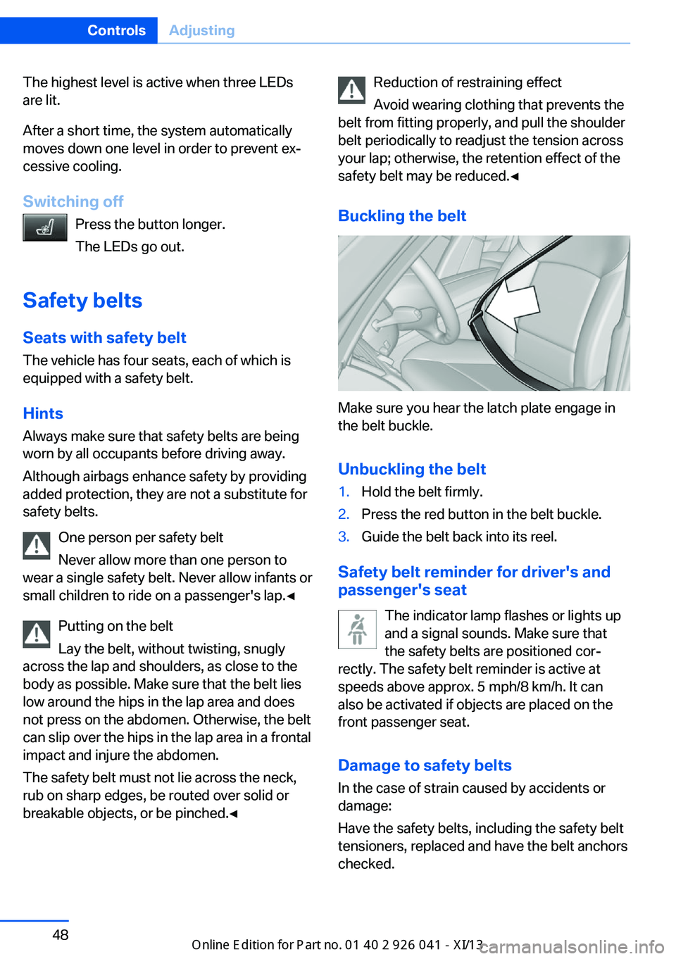
The highest level is active when three LEDs
are lit.
After a short time, the system automatically
moves down one level in order to prevent ex‐
cessive cooling.
Switching off Press the button longer.
The LEDs go out.
Safety belts
Seats with safety belt The vehicle has four seats, each of which is
equipped with a safety belt.
Hints
Always make sure that safety belts are being
worn by all occupants before driving away.
Although airbags enhance safety by providing
added protection, they are not a substitute for
safety belts.
One person per safety belt
Never allow more than one person to
wear a single safety belt. Never allow infants or
small children to ride on a passenger's lap.в—Ђ
Putting on the belt
Lay the belt, without twisting, snugly
across the lap and shoulders, as close to the
body as possible. Make sure that the belt lies
low around the hips in the lap area and does
not press on the abdomen. Otherwise, the belt
can slip over the hips in the lap area in a frontal
impact and injure the abdomen.
The safety belt must not lie across the neck,
rub on sharp edges, be routed over solid or
breakable objects, or be pinched.в—ЂReduction of restraining effect
Avoid wearing clothing that prevents the
belt from fitting properly, and pull the shoulder
belt periodically to readjust the tension across
your lap; otherwise, the retention effect of the
safety belt may be reduced.в—Ђ
Buckling the belt
Make sure you hear the latch plate engage in
the belt buckle.
Unbuckling the belt
1.Hold the belt firmly.2.Press the red button in the belt buckle.3.Guide the belt back into its reel.
Safety belt reminder for driver's and
passenger's seat
The indicator lamp flashes or lights up
and a signal sounds. Make sure that
the safety belts are positioned cor‐
rectly. The safety belt reminder is active at
speeds above approx. 5 mph/8 km/h. It can
also be activated if objects are placed on the
front passenger seat.
Damage to safety belts In the case of strain caused by accidents or
damage:
Have the safety belts, including the safety belt
tensioners, replaced and have the belt anchors checked.
Seite 48ControlsAdjusting48
Online Edition for Part no. 01 40 2 910 796 - VI/13
Page 55 of 214
Storing1.Switch on the ignition.2.Set the desired position.3. Press the button. The LED in the
button lights up.4.Press the desired button 1 or 2. The LED
goes out.
If the M button is pressed accidentally:
Press the button again.
The LED goes out.
Calling up settings Do not retrieve the memory while driving
Do not retrieve the memory setting while
driving, as an unexpected movement of the
seat or steering wheel could result in an acci‐
dent.в—Ђ
Comfort function
1.Open the driver's door.2.Switch off the ignition.3.Briefly press the desired button 1 or 2.
The corresponding seat position is performed
automatically.
The procedure stops when a switch for adjust‐
ing the seat or one of the buttons is pressed.
Safety mode
1.Close the driver's door or switch on the ig‐
nition.2.Press and hold the desired button 1 or 2
until the adjustment procedure is com‐
pleted.
Calling up of a seat position
deactivated
After a brief period, the calling up of stored
seat positions is deactivated to save battery
power.
To reactivate calling up of a seat position:
в–·Open or close the door or trunk lid.в–·Press a button on the remote control.в–·Press the Start/Stop button.
Mirrors
Exterior mirrors
At a glance
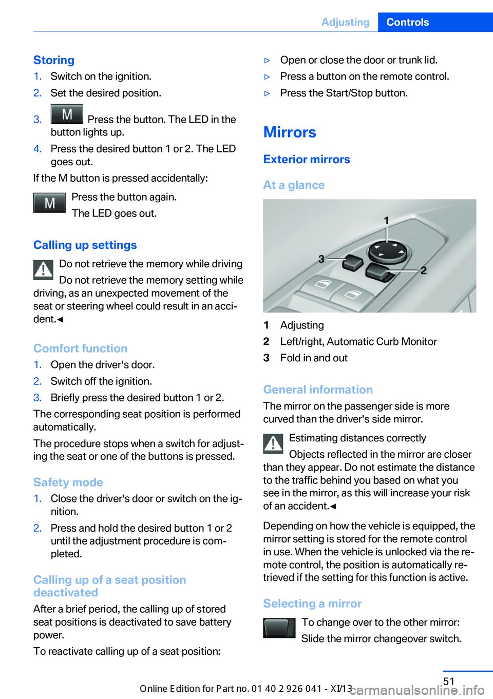
1Adjusting2Left/right, Automatic Curb Monitor3Fold in and out
General information
The mirror on the passenger side is more
curved than the driver's side mirror.
Estimating distances correctly
Objects reflected in the mirror are closer
than they appear. Do not estimate the distance
to the traffic behind you based on what you
see in the mirror, as this will increase your risk
of an accident.в—Ђ
Depending on how the vehicle is equipped, the
mirror setting is stored for the remote control
in use. When the vehicle is unlocked via the re‐
mote control, the position is automatically re‐
trieved if the setting for this function is active.
Selecting a mirror To change over to the other mirror:Slide the mirror changeover switch.
Seite 51AdjustingControls51
Online Edition for Part no. 01 40 2 910 796 - VI/13
Page 57 of 214
Steering wheel
General information Do not adjust while driving
Do not adjust the steering wheel while
driving; otherwise, an unexpected movement
could result in an accident.в—Ђ
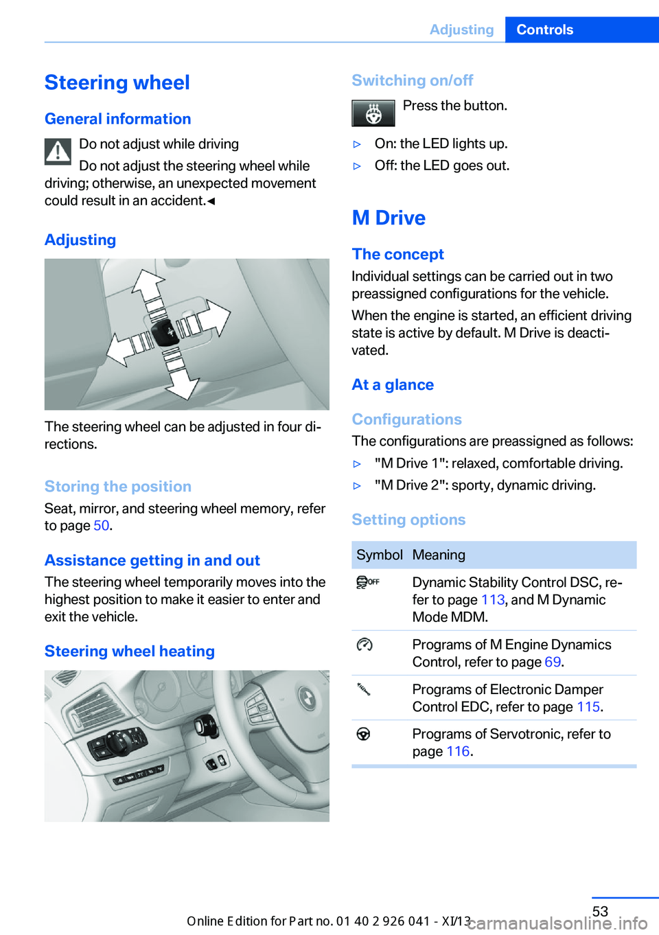
Adjusting
The steering wheel can be adjusted in four di‐
rections.
Storing the position Seat, mirror, and steering wheel memory, refer
to page 50.
Assistance getting in and out
The steering wheel temporarily moves into the
highest position to make it easier to enter and
exit the vehicle.
Steering wheel heating
Switching on/off Press the button.в–·On: the LED lights up.в–·Off: the LED goes out.
M Drive
The conceptIndividual settings can be carried out in two
preassigned configurations for the vehicle.
When the engine is started, an efficient driving
state is active by default. M Drive is deacti‐
vated.
At a glance
Configurations
The configurations are preassigned as follows:
в–·"M Drive 1": relaxed, comfortable driving.в–·"M Drive 2": sporty, dynamic driving.
Setting options
SymbolMeaning Dynamic Stability Control DSC, re‐
fer to page 113, and M Dynamic
Mode MDM. Programs of M Engine Dynamics
Control, refer to page 69. Programs of Electronic Damper
Control EDC, refer to page 115. Programs of Servotronic, refer to
page 116.Seite 53AdjustingControls53
Online Edition for Part no. 01 40 2 910 796 - VI/13
Page 63 of 214
DrivingVehicle equipment
All standard, country-specific and optional
equipment that is offered in the model series is
described in this chapter. Therefore, equip‐
ment is also described that is not available in a
vehicle, e. g., because of the selected optional
equipment or country variant. This also applies
for safety-related functions and systems.
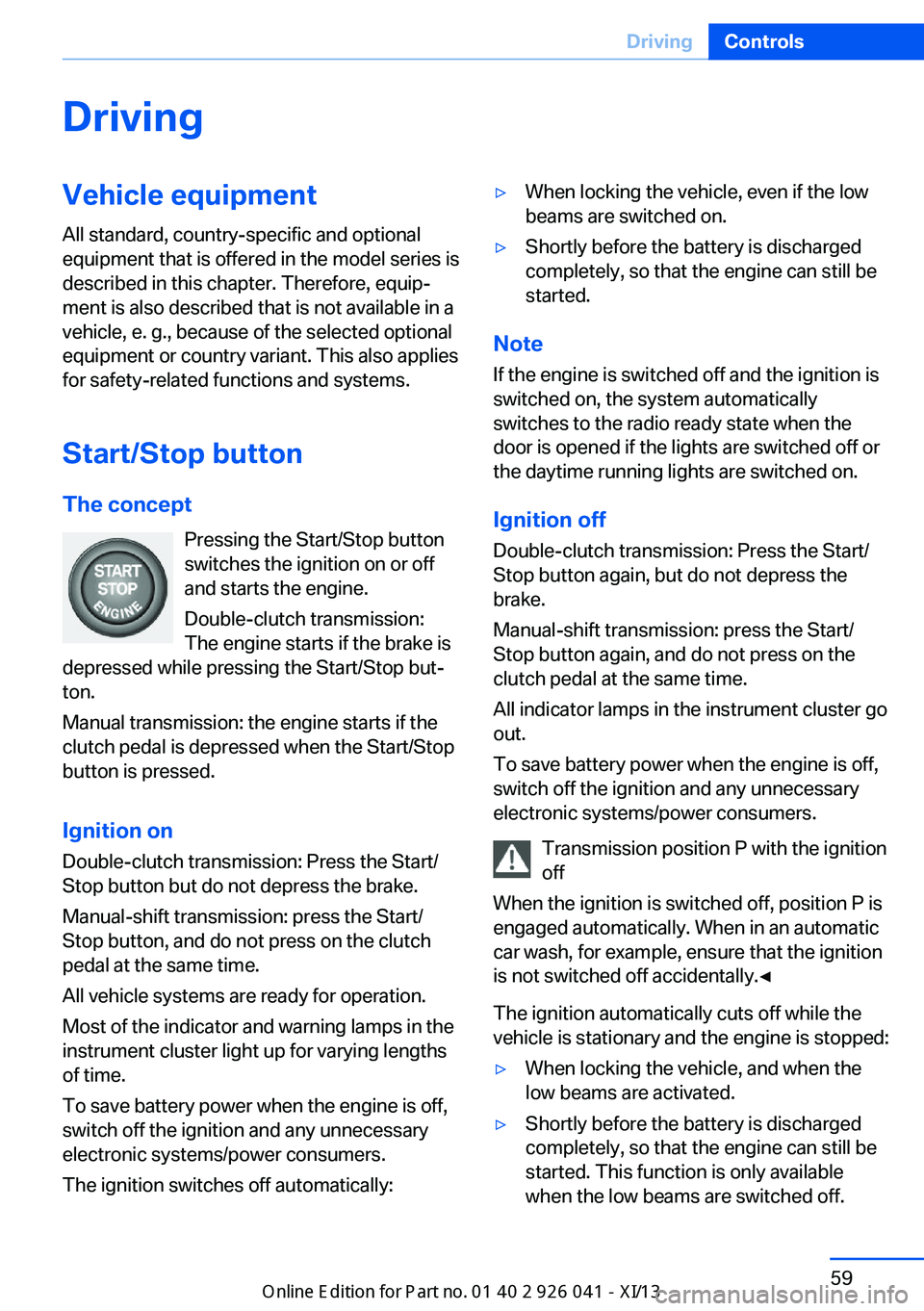
Start/Stop button The concept Pressing the Start/Stop button
switches the ignition on or off
and starts the engine.
Double-clutch transmission:
The engine starts if the brake is
depressed while pressing the Start/Stop but‐
ton.
Manual transmission: the engine starts if the
clutch pedal is depressed when the Start/Stop
button is pressed.
Ignition onDouble-clutch transmission: Press the Start/
Stop button but do not depress the brake.
Manual-shift transmission: press the Start/
Stop button, and do not press on the clutch
pedal at the same time.
All vehicle systems are ready for operation.
Most of the indicator and warning lamps in the
instrument cluster light up for varying lengths
of time.
To save battery power when the engine is off,
switch off the ignition and any unnecessary
electronic systems/power consumers.
The ignition switches off automatically:в–·When locking the vehicle, even if the low
beams are switched on.в–·Shortly before the battery is discharged
completely, so that the engine can still be
started.
Note
If the engine is switched off and the ignition is
switched on, the system automatically
switches to the radio ready state when the
door is opened if the lights are switched off or
the daytime running lights are switched on.
Ignition off
Double-clutch transmission: Press the Start/
Stop button again, but do not depress the
brake.
Manual-shift transmission: press the Start/
Stop button again, and do not press on the
clutch pedal at the same time.
All indicator lamps in the instrument cluster go
out.
To save battery power when the engine is off,
switch off the ignition and any unnecessary
electronic systems/power consumers.
Transmission position P with the ignition
off
When the ignition is switched off, position P is
engaged automatically. When in an automatic
car wash, for example, ensure that the ignition
is not switched off accidentally.в—Ђ
The ignition automatically cuts off while the
vehicle is stationary and the engine is stopped:
в–·When locking the vehicle, and when the
low beams are activated.в–·Shortly before the battery is discharged
completely, so that the engine can still be
started. This function is only available
when the low beams are switched off.Seite 59DrivingControls59
Online Edition for Part no. 01 40 2 910 796 - VI/13
Page 65 of 214
Engine stop
Hints Take the remote control with youTake the remote control with you when
leaving the vehicle so that children, for exam‐
ple, cannot start the engine.в—Ђ
Set the parking brake and further secure
the vehicle as required
Set the parking brake firmly when parking; oth‐
erwise, the vehicle could roll. On steep upward
and downward inclines, further secure the ve‐
hicle, for example, by turning the steering
wheel in the direction of the curb. в—Ђ
Before driving into a car wash
In order for the vehicle to be able to roll into a
car wash, heed the information regarding
Washing in automatic car washes, refer to
page 190.
Manual transmission
Switching off the engine1.With the vehicle at a standstill, press the
Start/Stop button.2.Shift into first gear or reverse.3.Set the parking brake.
Double-clutch transmission
Switching off the engine
1.Apply the brakes until the vehicle comes to
a stop.2.Press the Start/Stop button.
The engine is switched off.
The radio ready state is switched on.3.Set the parking brake.Automatic Engine Start/Stop
Function
The concept The Auto Start/Stop function helps save fuel.
The system switches off the engine during a
stop, e.g., in a traffic congestion or at traffic
lights. The ignition remains switched on. The
engine starts again automatically for driving
off.
Certain vehicle components may experience
additional wear as a result of this system.
Semi-automatic mode
After every start of the engine, the Auto Start
Stop function is in the last selected state, refer
to page 63. When the Auto Start Stop func‐
tion is active, it is available when the vehicle is
traveling faster than about 3 mph, approx.
5 km/h.
Engine stop
The engine is switched off automatically dur‐
ing a stop under the following conditions:
Double-clutch transmission:▷The selector lever is in transmission posi‐
tion D.в–·Brake pedal remains depressed while the
vehicle is stopped.▷The driver's seat belt is buckled or the driv‐
er's door is closed.
The air volume of the air conditioner is reduced
when the engine is switched off.
Displays in the instrument cluster The display indicates that the
automatic engine start-stop
function is ready for an auto‐
matic engine start.
Seite 61DrivingControls61
Online Edition for Part no. 01 40 2 910 796 - VI/13