park assist BMW M6 COUPE 2013 F13 Owner's Manual
[x] Cancel search | Manufacturer: BMW, Model Year: 2013, Model line: M6 COUPE, Model: BMW M6 COUPE 2013 F13Pages: 214, PDF Size: 7.08 MB
Page 16 of 214
CockpitVehicle equipment
All standard, country-specific and optional
equipment that is offered in the model series is
described in this chapter. Therefore, equip‐ment is also described that is not available in a
vehicle, e. g., because of the selected optional
equipment or country variant. This also applies
for safety-related functions and systems.
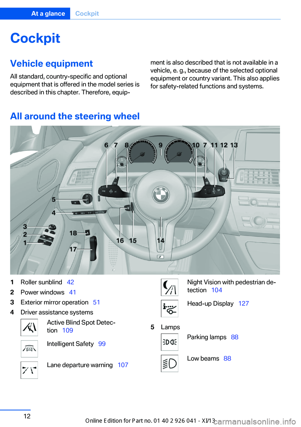
All around the steering wheel
1Roller sunblind 422Power windows 413Exterior mirror operation 514Driver assistance systemsActive Blind Spot Detec‐
tion 109Intelligent Safety 99Lane departure warning 107Night Vision with pedestrian de‐
tection 104Head-up Display 1275LampsParking lamps 88Low beams 88Seite 12At a glanceCockpit12
Online Edition for Part no. 01 40 2 910 796 - VI/13
Page 17 of 214
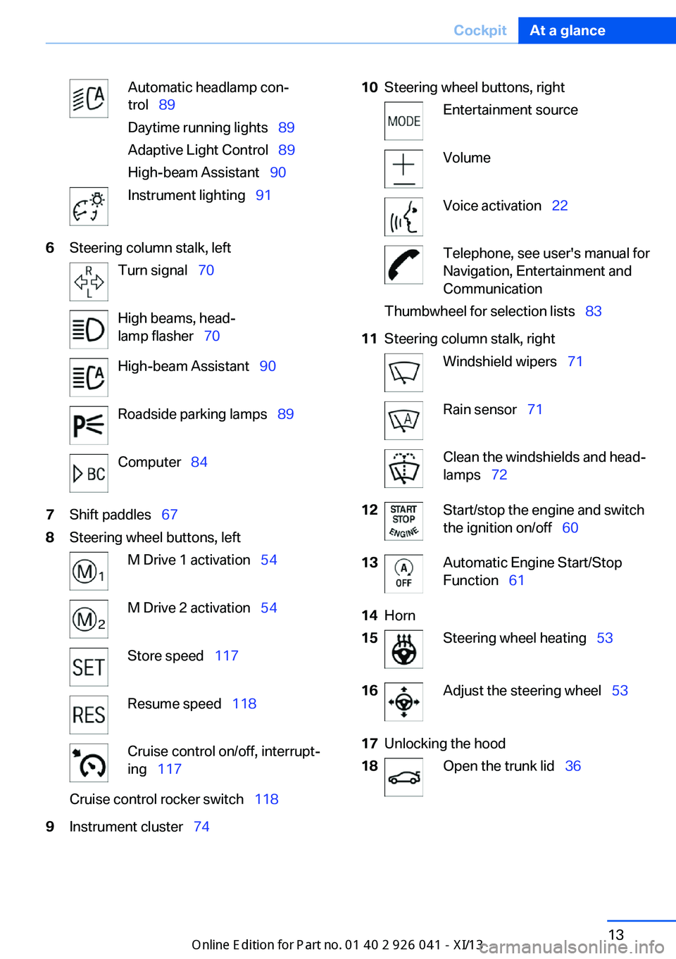
Automatic headlamp con‐
trol 89
Daytime running lights 89
Adaptive Light Control 89
High-beam Assistant 90Instrument lighting 916Steering column stalk, leftTurn signal 70High beams, head‐
lamp flasher 70High-beam Assistant 90Roadside parking lamps 89Computer 847Shift paddles 678Steering wheel buttons, leftM Drive 1 activation 54M Drive 2 activation 54Store speed 117Resume speed 118Cruise control on/off, interrupt‐
ing 117Cruise control rocker switch 1189Instrument cluster 7410Steering wheel buttons, rightEntertainment sourceVolumeVoice activation 22Telephone, see user's manual for
Navigation, Entertainment and
CommunicationThumbwheel for selection lists 8311Steering column stalk, rightWindshield wipers 71Rain sensor 71Clean the windshields and head‐
lamps 7212Start/stop the engine and switch
the ignition on/off 6013Automatic Engine Start/Stop
Function 6114Horn15Steering wheel heating 5316Adjust the steering wheel 5317Unlocking the hood18Open the trunk lid 36Seite 13CockpitAt a glance13
Online Edition for Part no. 01 40 2 910 796 - VI/13
Page 69 of 214
It may take several seconds for the brake to be
put into operation. Any sounds associated with
this are normal.
The indicator lamp in the instrument
cluster goes out as soon as the parking
brake is ready for operation.
Lower lamp: indicator lamp in Canadian
models.
M double-clutch
transmission with Drivelogic
The conceptThe M double-clutch transmission with Drive‐
logic is an automatic shift transmission with
two clutches and partial transmissions in which
the gears can be changed without interrupting
the tractive force.
The operation is via the shift lever or two shift
paddles on the steering wheel.
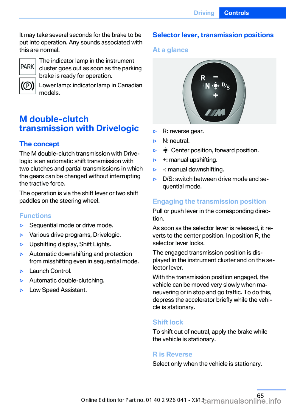
Functions▷Sequential mode or drive mode.▷Various drive programs, Drivelogic.▷Upshifting display, Shift Lights.▷Automatic downshifting and protection
from misshifting even in sequential mode.▷Launch Control.▷Automatic double-clutching.▷Low Speed Assistant.Selector lever, transmission positions
At a glance▷R: reverse gear.▷N: neutral.▷ Center position, forward position.▷+: manual upshifting.▷-: manual downshifting.▷D/S: switch between drive mode and se‐
quential mode.
Engaging the transmission position
Pull or push lever in the corresponding direc‐
tion.
As soon as the selector lever is released, it re‐
verts to the center position. In position R, the
selector lever locks.
The engaged transmission position is dis‐
played in the instrument cluster and on the se‐
lector lever.
With the transmission position engaged, the
vehicle can be moved very slowly when ma‐
neuvering or in stop and go traffic. To do this,
depress the accelerator briefly while the vehi‐
cle is stationary.
Shift lock
To shift out of neutral, apply the brake while
the vehicle is stationary.
R is Reverse
Select only when the vehicle is stationary.
Seite 65DrivingControls65
Online Edition for Part no. 01 40 2 910 796 - VI/13
Page 80 of 214
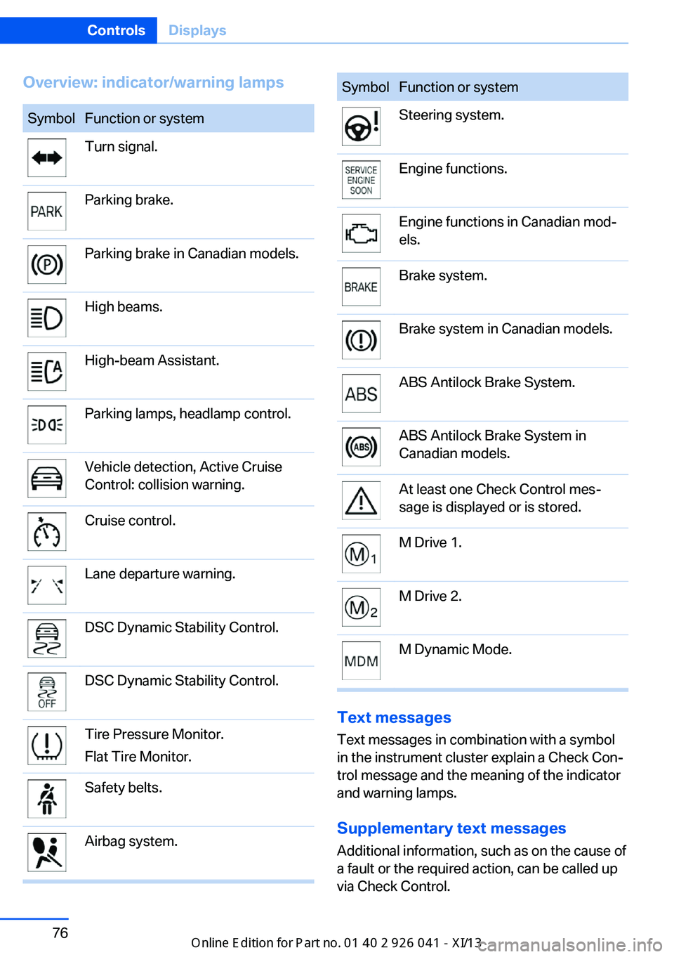
Overview: indicator/warning lampsSymbolFunction or systemTurn signal.Parking brake.Parking brake in Canadian models.High beams.High-beam Assistant.Parking lamps, headlamp control.Vehicle detection, Active Cruise
Control: collision warning.Cruise control.Lane departure warning.DSC Dynamic Stability Control.DSC Dynamic Stability Control.Tire Pressure Monitor.
Flat Tire Monitor.Safety belts.Airbag system.SymbolFunction or systemSteering system.Engine functions.Engine functions in Canadian mod‐
els.Brake system.Brake system in Canadian models.ABS Antilock Brake System.ABS Antilock Brake System in
Canadian models.At least one Check Control mes‐
sage is displayed or is stored.M Drive 1.M Drive 2.M Dynamic Mode.
Text messages
Text messages in combination with a symbol
in the instrument cluster explain a Check Con‐ trol message and the meaning of the indicator
and warning lamps.
Supplementary text messages
Additional information, such as on the cause of
a fault or the required action, can be called up
via Check Control.
Seite 76ControlsDisplays76
Online Edition for Part no. 01 40 2 910 796 - VI/13
Page 92 of 214
LampsVehicle equipment
All standard, country-specific and optional
equipment that is offered in the model series is
described in this chapter. Therefore, equip‐
ment is also described that is not available in a
vehicle, e. g., because of the selected optional
equipment or country variant. This also applies
for safety-related functions and systems.
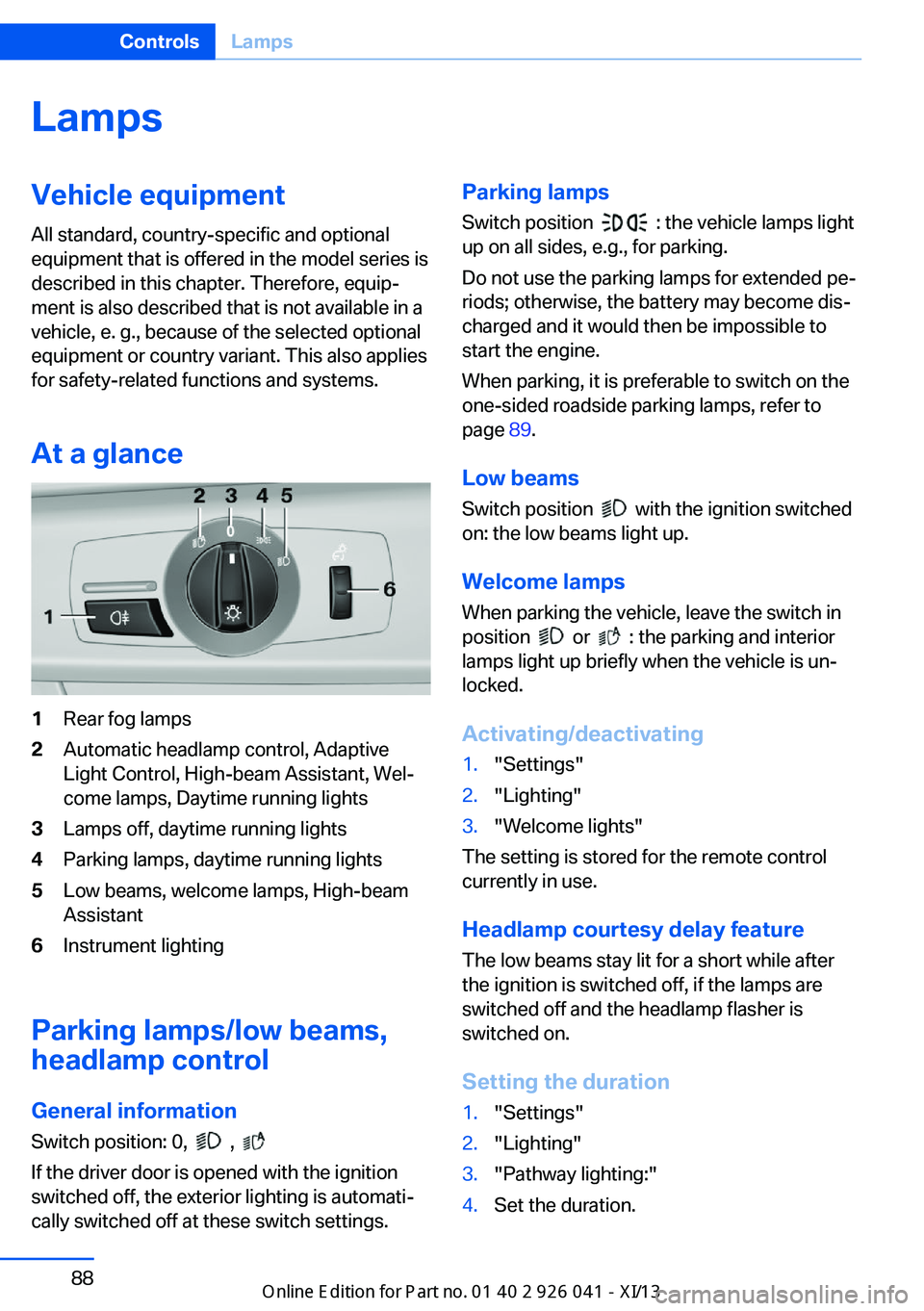
At a glance1Rear fog lamps2Automatic headlamp control, Adaptive
Light Control, High-beam Assistant, Wel‐
come lamps, Daytime running lights3Lamps off, daytime running lights4Parking lamps, daytime running lights5Low beams, welcome lamps, High-beam
Assistant6Instrument lighting
Parking lamps/low beams,
headlamp control
General information Switch position: 0,
,
If the driver door is opened with the ignition
switched off, the exterior lighting is automati‐
cally switched off at these switch settings.
Parking lamps
Switch position
: the vehicle lamps light
up on all sides, e.g., for parking.
Do not use the parking lamps for extended pe‐
riods; otherwise, the battery may become dis‐
charged and it would then be impossible to
start the engine.
When parking, it is preferable to switch on the
one-sided roadside parking lamps, refer to
page 89.
Low beams Switch position
with the ignition switched
on: the low beams light up.
Welcome lamps When parking the vehicle, leave the switch in
position
or : the parking and interior
lamps light up briefly when the vehicle is un‐
locked.
Activating/deactivating
1."Settings"2."Lighting"3."Welcome lights"
The setting is stored for the remote control
currently in use.
Headlamp courtesy delay feature
The low beams stay lit for a short while after
the ignition is switched off, if the lamps are
switched off and the headlamp flasher is
switched on.
Setting the duration
1."Settings"2."Lighting"3."Pathway lighting:"4.Set the duration.Seite 88ControlsLamps88
Online Edition for Part no. 01 40 2 910 796 - VI/13
Page 117 of 214
Driving stability control systemsVehicle equipmentAll standard, country-specific and optional
equipment that is offered in the model series is
described in this chapter. Therefore, equip‐
ment is also described that is not available in a
vehicle, e. g., because of the selected optional
equipment or country variant. This also applies
for safety-related functions and systems.
Antilock Brake System ABS ABS prevents locking of the wheels during
braking.
The vehicle remains steerable even during full
brake applications, thus increasing active
safety.
ABS is operational every time you start the en‐
gine.
Brake assistant
When you apply the brakes rapidly, this system
automatically produces the maximum braking
force boost. This then reduces braking dis‐ tance to a minimum during full braking. This
system utilizes all of the benefits provided by ABS.
Do not reduce the pressure on the brake pedal
for the duration of the full braking.
Drive-off assistantThis system supports driving away on gradi‐
ents. The parking brake is not required.1.Hold the vehicle in place with the foot
brake.2.Release the foot brake and drive away
without delay.After the foot brake is released, the vehicle is
held in place for approx. 2 seconds.
Depending on the vehicle load, the vehicle may
roll back slightly.
Driving off without delay
After releasing the foot brake, start driv‐
ing without delay, since the drive-off assistant
will not hold the vehicle in place for more than
approx. 2 seconds and the vehicle will begin
rolling back.◀
DSC Dynamic Stability
Control
The concept DSC prevents traction loss in the driving
wheels when driving away and accelerating.
DSC also recognizes unstable vehicle condi‐
tions, such as fishtailing or nose-diving. Sub‐
ject to physical limits, DSC helps to keep the
vehicle on a steady course by reducing engine
speed and by applying brakes at individual
wheels.
Adjust your driving style to the situation
An appropriate driving style is always the
responsibility of the driver.
The laws of physics cannot be repealed, even
with DSC.
Therefore, do not reduce the additional safety
margin by driving in a risky manner.◀
Indicator/warning lamps The indicator lamp flashes: DSC con‐
trols the drive forces and brake forces.
The indicator lamp lights up: DSC has
failed.Seite 113Driving stability control systemsControls113
Online Edition for Part no. 01 40 2 910 796 - VI/13
Page 125 of 214
System limits
Limits of ultrasonic measurement
The detection of objects can reach the physi‐
cal limits of ultrasonic measurement, e.g.:▷With tow bars and trailer hitches.▷With thin or wedge-shaped objects.▷With low objects.▷With objects with corners and sharp edges.
Low objects already displayed, e.g., curbs, can
move into the blind area of the sensors before
or after a continuous tone sounds.
High, protruding objects such as ledges may
not be detected.
False warnings
PDC may issue a warning under the following
conditions even though there is no obstacle
within the detection range:
▷In heavy rain.▷When sensors are very dirty or covered in
ice.▷When sensors are covered in snow.▷On rough road surfaces.▷In large buildings with right angles and
smooth walls, e.g., in underground ga‐
rages.▷In heavy exhaust.▷Due to other ultrasound sources, e.g.,
sweeping machines, high pressure steam
cleaners or neon lights.
Malfunction
A Check Control message is displayed.
The range of the sensors is shown as a shaded
area on the Control Display.
PDC has failed. Have the system checked.
To ensure full operability:
▷Keep the sensors clean and free of ice.▷When using high-pressure washers, do not
spray the sensors for long periods and
maintain a distance of at least 12 in/30 cm.
Surround View
The concept Surround View comprises various camera as‐
sistance systems that help the driver when
parking, maneuvering, and at complex exits
and intersections.
▷Rearview camera, refer to page 121▷Side View, refer to page 126.▷Top View, refer to page 124.
Backup camera
The concept
The backup camera provides assistance in
parking and maneuvering backwards. The area
behind the vehicle is shown on the Control
Display.
Hints Check the traffic situation as well
Check the traffic situation around the ve‐
hicle with your own eyes. Otherwise, an acci‐
dent could result from road users or objects lo‐
cated outside the picture area of the backup
camera.◀
Seite 121Driving comfortControls121
Online Edition for Part no. 01 40 2 910 796 - VI/13
Page 126 of 214
At a glance
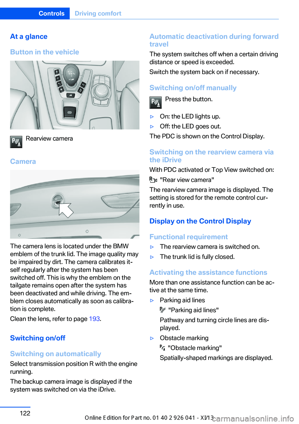
Button in the vehicle
Rearview camera
Camera
The camera lens is located under the BMW
emblem of the trunk lid. The image quality may
be impaired by dirt. The camera calibrates it‐
self regularly after the system has been
switched off. This is why the emblem on the
tailgate remains open after the system has
been deactivated and while driving. The em‐
blem closes automatically as soon as calibra‐
tion is complete.
Clean the lens, refer to page 193.
Switching on/off
Switching on automatically Select transmission position R with the engine
running.
The backup camera image is displayed if the
system was switched on via the iDrive.
Automatic deactivation during forward
travel
The system switches off when a certain driving
distance or speed is exceeded.
Switch the system back on if necessary.
Switching on/off manually Press the button.▷On: the LED lights up.▷Off: the LED goes out.
The PDC is shown on the Control Display.
Switching on the rearview camera via
the iDrive
With PDC activated or Top View switched on:
"Rear view camera"
The rearview camera image is displayed. The
setting is stored for the remote control cur‐
rently in use.
Display on the Control Display
Functional requirement
▷The rearview camera is switched on.▷The trunk lid is fully closed.
Activating the assistance functions
More than one assistance function can be ac‐
tive at the same time.
▷Parking aid lines
"Parking aid lines"
Pathway and turning circle lines are dis‐
played.
▷Obstacle marking
"Obstacle marking"
Spatially-shaped markings are displayed.
Seite 122ControlsDriving comfort122
Online Edition for Part no. 01 40 2 910 796 - VI/13
Page 128 of 214
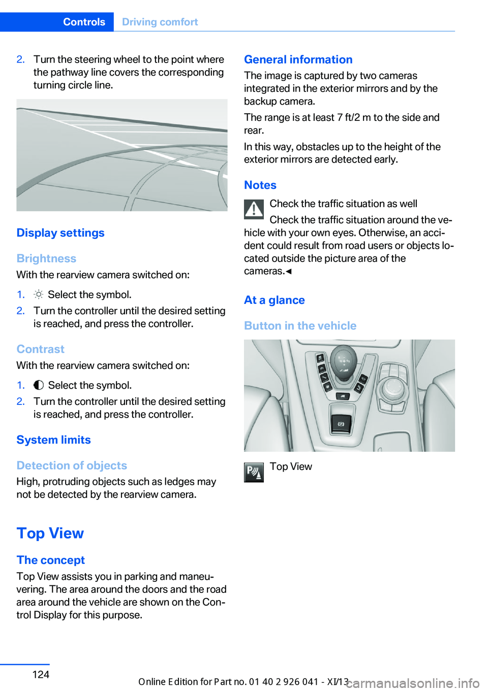
2.Turn the steering wheel to the point where
the pathway line covers the corresponding
turning circle line.
Display settings
Brightness
With the rearview camera switched on:
1. Select the symbol.2.Turn the controller until the desired setting
is reached, and press the controller.
Contrast
With the rearview camera switched on:
1. Select the symbol.2.Turn the controller until the desired setting
is reached, and press the controller.
System limits
Detection of objects
High, protruding objects such as ledges may
not be detected by the rearview camera.
Top View The concept
Top View assists you in parking and maneu‐
vering. The area around the doors and the road
area around the vehicle are shown on the Con‐
trol Display for this purpose.
General information
The image is captured by two cameras
integrated in the exterior mirrors and by the
backup camera.
The range is at least 7 ft/2 m to the side and
rear.
In this way, obstacles up to the height of the
exterior mirrors are detected early.
Notes Check the traffic situation as well
Check the traffic situation around the ve‐
hicle with your own eyes. Otherwise, an acci‐
dent could result from road users or objects lo‐
cated outside the picture area of the
cameras.◀
At a glance
Button in the vehicle
Top View
Seite 124ControlsDriving comfort124
Online Edition for Part no. 01 40 2 910 796 - VI/13
Page 130 of 214
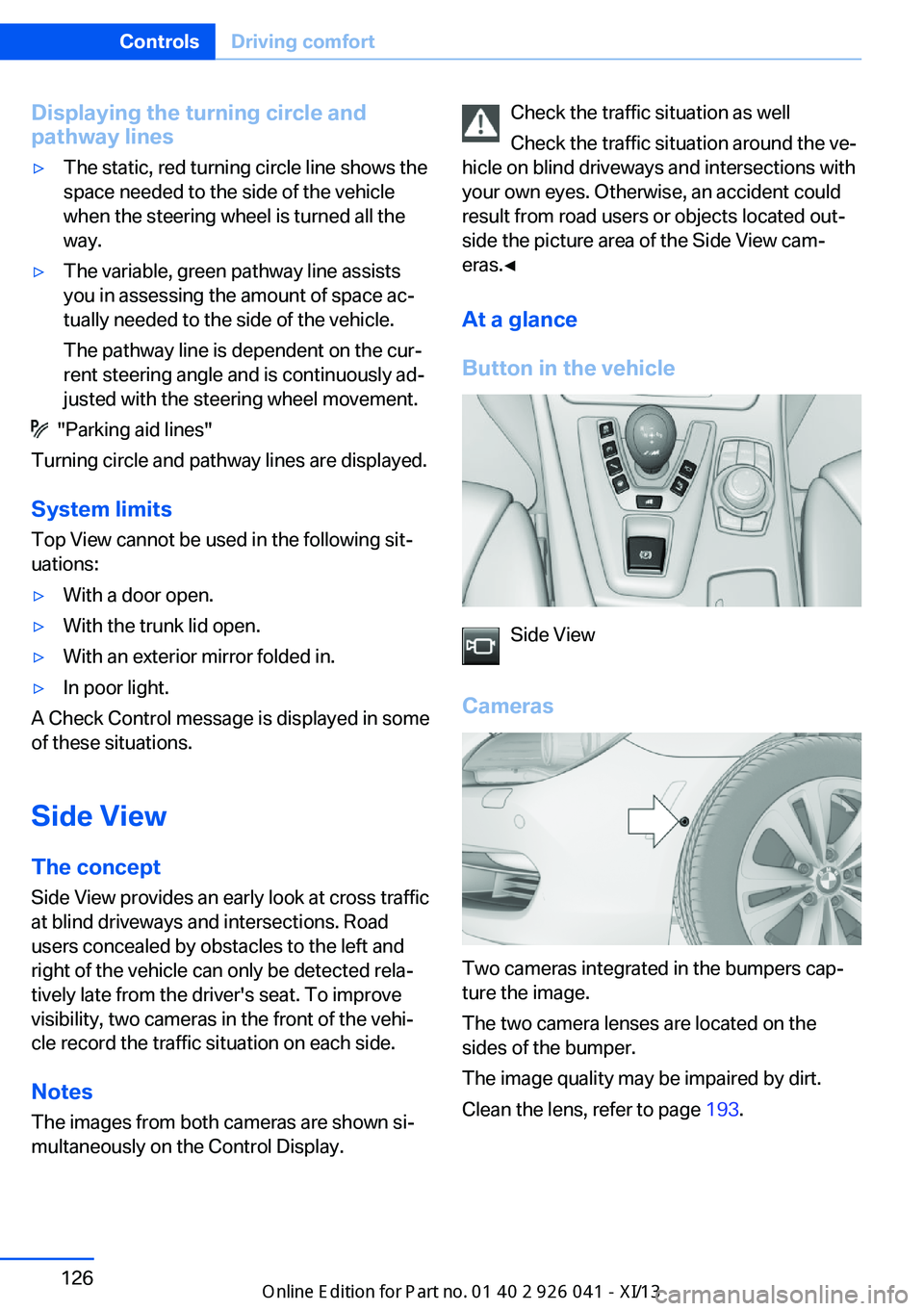
Displaying the turning circle and
pathway lines▷The static, red turning circle line shows the
space needed to the side of the vehicle
when the steering wheel is turned all the
way.▷The variable, green pathway line assists
you in assessing the amount of space ac‐
tually needed to the side of the vehicle.
The pathway line is dependent on the cur‐
rent steering angle and is continuously ad‐
justed with the steering wheel movement.
"Parking aid lines"
Turning circle and pathway lines are displayed.
System limits
Top View cannot be used in the following sit‐
uations:
▷With a door open.▷With the trunk lid open.▷With an exterior mirror folded in.▷In poor light.
A Check Control message is displayed in some
of these situations.
Side View The concept Side View provides an early look at cross traffic
at blind driveways and intersections. Road
users concealed by obstacles to the left and
right of the vehicle can only be detected rela‐
tively late from the driver's seat. To improve
visibility, two cameras in the front of the vehi‐
cle record the traffic situation on each side.
Notes
The images from both cameras are shown si‐
multaneously on the Control Display.
Check the traffic situation as well
Check the traffic situation around the ve‐
hicle on blind driveways and intersections with
your own eyes. Otherwise, an accident could
result from road users or objects located out‐
side the picture area of the Side View cam‐
eras.◀
At a glance
Button in the vehicle
Side View
Cameras
Two cameras integrated in the bumpers cap‐
ture the image.
The two camera lenses are located on the
sides of the bumper.
The image quality may be impaired by dirt.
Clean the lens, refer to page 193.
Seite 126ControlsDriving comfort126
Online Edition for Part no. 01 40 2 910 796 - VI/13