power steering BMW M6 COUPE 2014 F13M Owner's Manual
[x] Cancel search | Manufacturer: BMW, Model Year: 2014, Model line: M6 COUPE, Model: BMW M6 COUPE 2014 F13MPages: 222, PDF Size: 4.8 MB
Page 18 of 222
CockpitVehicle features and options
This chapter describes all standard, country-
specific and optional features offered with the
series. It also describes features that are notnecessarily available in your car, e. g., due to
the selected options or country versions. This
also applies to safety-related functions and
systems.
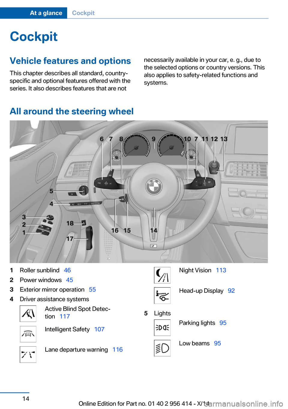
All around the steering wheel
1Roller sunblind 462Power windows 453Exterior mirror operation 554Driver assistance systemsActive Blind Spot Detec‐
tion 117Intelligent Safety 107Lane departure warning 116Night Vision 113Head-up Display 925LightsParking lights 95Low beams 95Seite 14At a glanceCockpit14
Online Edition for Part no. 01 40 2 956 414 - X/14
Page 59 of 222
Safety mode1.Close the driver's door or reel on the igni‐
tion.2.Press and hold the desired button 1 or 2
until the adjustment procedure is com‐
pleted.
Calling up of a seat position
deactivated
After a brief period, calling up stored seat posi‐
tions is deactivated to save battery power.
To reactivate calling up of a seat position:
▷Open or close the door or trunk lid.▷Press a button on the remote control.▷Press the Start/Stop button.
Mirrors
Exterior mirrors
General information The mirror on the passenger side is more
curved than the driver's side mirror.
Depending on the vehicle equipment, the mir‐
ror setting is stored for the profile currently in
use. When the vehicle is unlocked via the re‐
mote control, the position is automatically re‐
trieved if this function is active.
Note Estimating distances correctly
Objects reflected in the mirror are closer
than they appear. Do not estimate the distance
to the traffic behind you based on what you
see in the mirror, as this will increase your risk
of an accident.◀
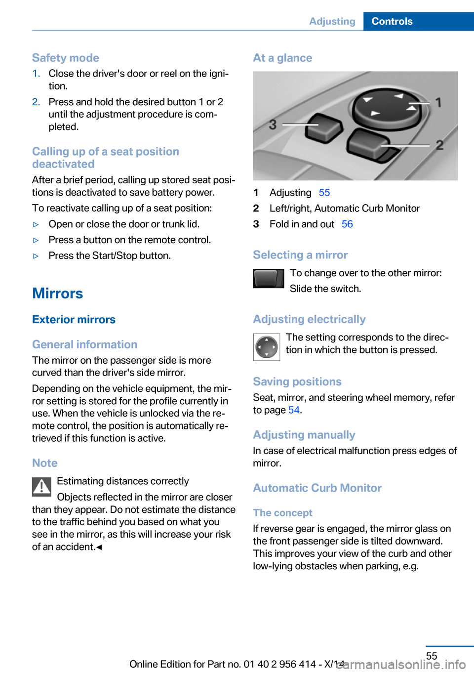
At a glance1Adjusting 552Left/right, Automatic Curb Monitor3Fold in and out 56
Selecting a mirror
To change over to the other mirror:
Slide the switch.
Adjusting electrically The setting corresponds to the direc‐
tion in which the button is pressed.
Saving positions
Seat, mirror, and steering wheel memory, refer
to page 54.
Adjusting manually In case of electrical malfunction press edges of
mirror.
Automatic Curb Monitor The concept
If reverse gear is engaged, the mirror glass on
the front passenger side is tilted downward.
This improves your view of the curb and other
low-lying obstacles when parking, e.g.
Seite 55AdjustingControls55
Online Edition for Part no. 01 40 2 956 414 - X/14
Page 126 of 222
Driving stability control systemsVehicle features and optionsThis chapter describes all standard, country-
specific and optional features offered with the
series. It also describes features that are not
necessarily available in your car, e. g., due to
the selected options or country versions. This
also applies to safety-related functions and
systems.
Antilock Brake System ABS
ABS prevents locking of the wheels during
braking.
The vehicle contains its steering power even
during full brake applications, thus increasing
active safety.
ABS is operational every time you start the en‐
gine.
Brake assistant
When you apply the brakes rapidly, this system
automatically produces the greatest possible
braking force boost. It reduces the braking dis‐
tance to a minimum during emergency stop.
This system utilizes all of the benefits provided
by ABS.
Do not reduce the pressure on the brake pedal
for the duration of the emergency stop.
Drive-off assistant
This system supports driving off on inclines.
The parking brake is not required.1.Hold the vehicle in place with the foot
brake.2.Release the foot brake and drive off with‐
out delay.After the foot brake is released, the vehicle is
held in place for approx. 2 seconds.
Depending on the vehicle load, the vehicle may
roll back slightly.
Driving off without delay
After releasing the foot brake, start driv‐
ing without delay, since the drive-off assistant
will not hold the vehicle in place for more than
approx. 2 seconds and the vehicle will begin to
roll back.◀
DSC Dynamic Stability
Control
The concept DSC prevents traction loss in the power
wheels when driving off and accelerating.
DSC also recognizes unstable vehicle condi‐
tions such as fishtailing or nose-diving. Within
the physical limits DSC helps to keep the vehi‐
cle on a steady course by reducing engine
speed and by applying brakes to the individual
wheels.
Note Adjust your driving style to the situation
An appropriate driving style is always the
responsibility of the driver.
The laws of physics cannot be repealed, not
even with DSC.
Therefore, do not reduce the additional safety
margin by driving in a risky manner.◀
Do not deactivate DSC when driving with
roof load
Do not deactivate Dynamic Stability Control DSC when driving with roof load, e.g. roof-
mounted luggage rack.Seite 122ControlsDriving stability control systems122
Online Edition for Part no. 01 40 2 956 414 - X/14
Page 127 of 222
Otherwise, driving safety is not given in driv‐
ing-critical situation due to the elevated center
of gravity.◀
At a glance
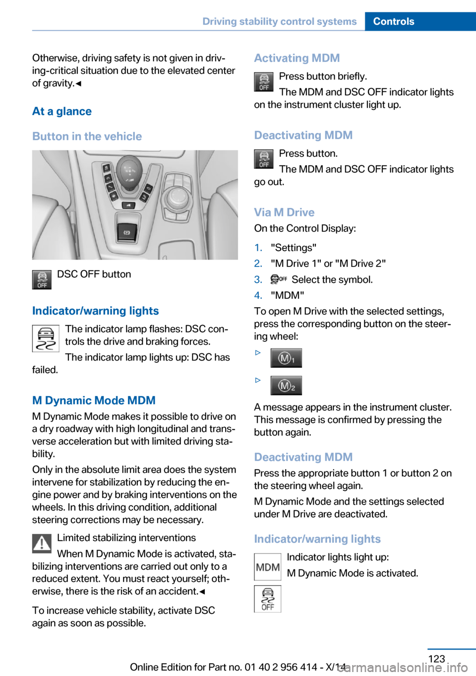
Button in the vehicle
DSC OFF button
Indicator/warning lights The indicator lamp flashes: DSC con‐
trols the drive and braking forces.
The indicator lamp lights up: DSC has
failed.
M Dynamic Mode MDM
M Dynamic Mode makes it possible to drive on
a dry roadway with high longitudinal and trans‐
verse acceleration but with limited driving sta‐
bility.
Only in the absolute limit area does the system
intervene for stabilization by reducing the en‐
gine power and by braking interventions on the
wheels. In this driving condition, additional
steering corrections may be necessary.
Limited stabilizing interventions
When M Dynamic Mode is activated, sta‐
bilizing interventions are carried out only to a
reduced extent. You must react yourself; oth‐
erwise, there is the risk of an accident.◀
To increase vehicle stability, activate DSC
again as soon as possible.
Activating MDM
Press button briefly.
The MDM and DSC OFF indicator lights
on the instrument cluster light up.
Deactivating MDM Press button.
The MDM and DSC OFF indicator lights
go out.
Via M Drive On the Control Display:1."Settings"2."M Drive 1" or "M Drive 2"3. Select the symbol.4."MDM"
To open M Drive with the selected settings,
press the corresponding button on the steer‐
ing wheel:
▷▷
A message appears in the instrument cluster.
This message is confirmed by pressing the
button again.
Deactivating MDM
Press the appropriate button 1 or button 2 on
the steering wheel again.
M Dynamic Mode and the settings selected
under M Drive are deactivated.
Indicator/warning lights Indicator lights light up:
M Dynamic Mode is activated.
Seite 123Driving stability control systemsControls123
Online Edition for Part no. 01 40 2 956 414 - X/14
Page 195 of 222
Vehicle batteryMaintenance
The battery is maintenance-free.
The added amount of acid is sufficient for the
service life of the battery.
Further information about the battery can be
obtained from your service center.
Battery replacement Use approved vehicle batteries only
Only use vehicle batteries that have been
approved for your vehicle by the manufacturer;
otherwise, the vehicle could be damaged and
systems or functions may not be fully availa‐
ble.◀
After a battery replacement, have the battery
registered on the vehicle by your service cen‐
ter to ensure that all comfort features are fully
available and that any Check Control mes‐
sages of these comfort features are no longer
displayed.
Charging the battery
Note Do not connect charging devices to the12 volt socket in the vehicle
Do not connect battery chargers to the fac‐
tory-installed 12 volt sockets in the vehicle as
this may damage the vehicle battery due to an
increased power consumption.◀
General information Make sure that the battery is always suffi‐
ciently charged to guarantee that the battery
remains usable for its full service life.
The battery may need to be charged in the fol‐
lowing cases:▷When making frequent short-distance
drives.▷If the vehicle is not used for prolonged pe‐
riods, longer than a month.
Starting aid terminals
In the vehicle, only charge the battery via the
starting aid terminals, refer to page 195, in the
engine compartment with the engine off.
Power failure After a temporary power loss, some equipment
needs to be newly initialized or individual set‐
tings updated, e.g.:
▷Seat, mirror, and steering wheel memory:
store the positions again.▷Time: update.▷Date: update.▷Glass sunroof: initialize the system, refer to
page 47.
Disposing of old batteries
Have old batteries disposed of by your
service center or bring them to a recy‐
cling center.
Maintain the battery in an upright position for
transport and storage. Secure the battery so
that it does not tip over during transport.
Fuses Hints Replacing fuses
Never attempt to repair a blown fuse and
do not replace a defective fuse with a substi‐
tute of another color or amperage rating; this
could lead to a circuit overload, ultimately re‐
sulting in a fire in the vehicle.◀
Plastic tweezers and information on the fuse
types and locations are stored in the fuse box
in the cargo area.
Seite 191Replacing componentsMobility191
Online Edition for Part no. 01 40 2 956 414 - X/14
Page 200 of 222
corresponding engine or body ground of
the vehicle to be started.
Starting the engine
Never use spray fluids to start the engine.
1.Start the engine of the assisting vehicle
and let it run for several minutes at an in‐
creased idle speed.2.Start the engine of the vehicle that is to be
started in the usual way.
If the first starting attempt is not success‐
ful, wait a few minutes before making an‐
other attempt in order to allow the dis‐
charged battery to recharge.3.Let both engines run for several minutes.4.Disconnect the jumper cables in the re‐
verse order.
Check the battery and recharge if needed.
Tow-starting and towing Note Tow-starting and towing
For towing the vehicle turn, switch off the
Intelligent Safety systems; otherwise malfunc‐
tions of the individual braking systems might
lead to accidents.◀
Manual transmission
Observe before towing your vehicle Gearshift lever in neutral position.
Towing When the parking brake is blocked
The parking brake cannot be released
manually.
Do not tow the vehicle with the parking brake
blocked, or the vehicle can be damaged.
Contact your service center.◀
Follow the towing instructions
Follow all towing instructions; otherwise,
vehicle damage or accidents may occur.◀▷Make sure that the ignition is switched on;
otherwise, the low beams, tail lights, turn
signals, and wipers may be unavailable.▷Do not tow the vehicle with the rear axle
tilted, as the front wheels could turn.▷When the engine is stopped, there is no
power assist. Consequently, more force
needs to be applied when braking and
steering.▷Larger steering wheel movements are re‐
quired.▷The towing vehicle must not be lighter
than the vehicle being towed; otherwise,
it will not be possible to control the vehi‐
cle's response.
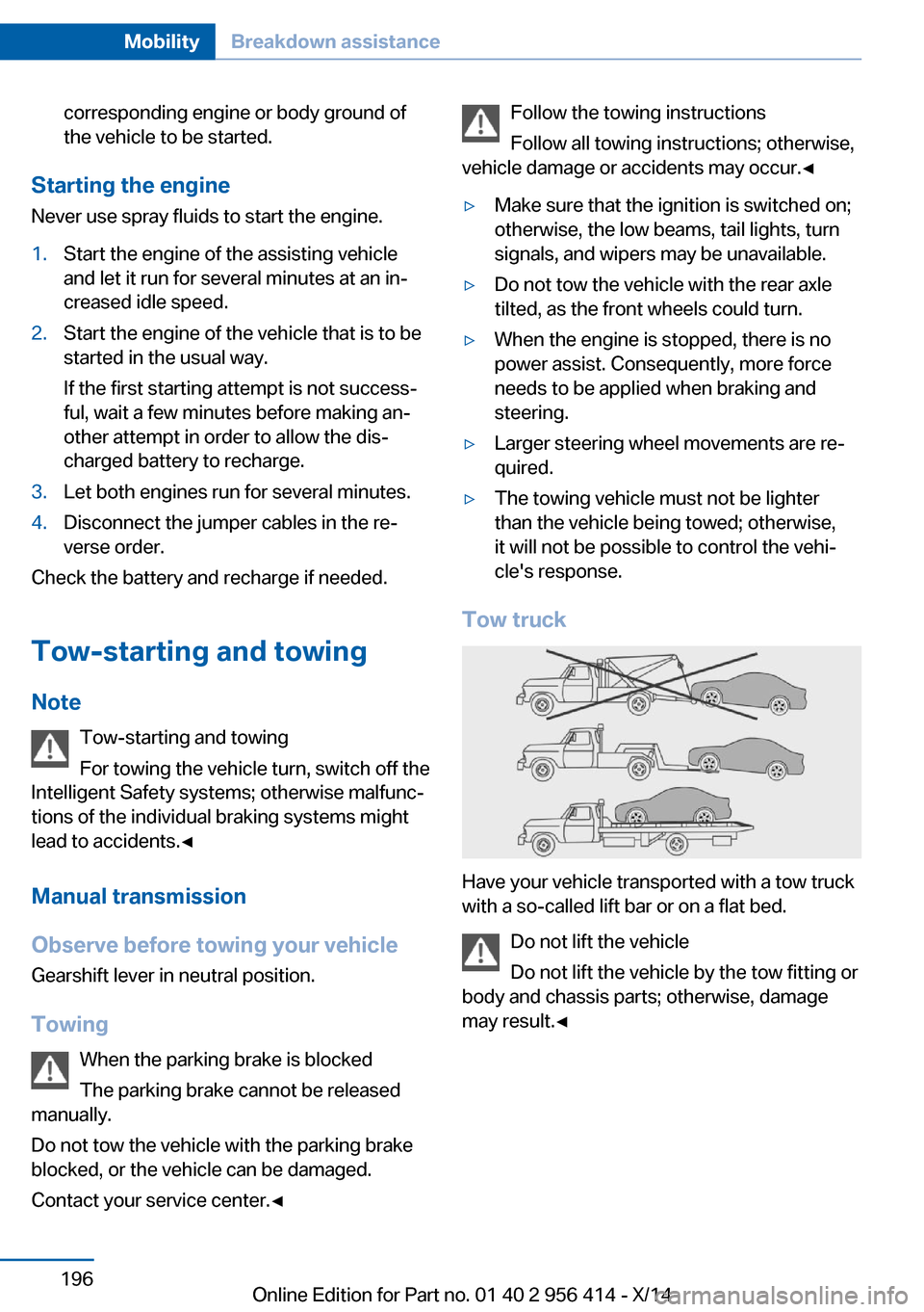
Tow truck
Have your vehicle transported with a tow truck
with a so-called lift bar or on a flat bed.
Do not lift the vehicle
Do not lift the vehicle by the tow fitting or
body and chassis parts; otherwise, damage
may result.◀
Seite 196MobilityBreakdown assistance196
Online Edition for Part no. 01 40 2 956 414 - X/14
Page 218 of 222
Pedestrian detection, seeNight Vision 113
Pedestrian warning with city braking function 110
Personal Profile 35
Personal Profile, exporting profiles 36
Pinch protection system, glass sunroof 47
Pinch protection system, win‐ dows 45
Plastic, care 201
Power failure 191
Power sunroof, glass 46
Power windows 45
Pressure, tire air pres‐ sure 170
Pressure warning FTM, tires 106
Preventing Auto Start Stop 66
Profile, refer to Personal Pro‐ file 35
Programmable memory but‐ tons, iDrive 23
Protective function, glass sunroof 47
Protective function, win‐ dows 45
Push-and-turn reel, refer to Controller 18
R Radiator fluid 184
Radio-operated key, refer to Remote control 34
Radio ready state 64
Radio, see user's manual for Navigation, Entertainment
and Communication
Rain sensor 70
Rear lights 189
Rearview camera 131
Rearview mirror 55
Rear window defroster 140 Recirculated-air mode 139
Recommended fuel grade 168
Recommended tire brands 174
Refueling 166
Remaining range 84
Remote control/key 34
Remote control, malfunc‐ tion 38
Remote control, univer‐ sal 142
Replacement fuse 191
Replacing bulbs, see Lamp replacement 187
Replacing parts 187
Replacing wheels/tires 174
Reporting safety defects 9
RES button, see Cruise con‐ trol 127
Reserve warning, refer to Range 84
Reset, Tire Pressure Monitor TPM 104
Residual heat, automatic cli‐ mate control 140
Retaining straps, securing cargo 161
Retreaded tires 174
Reversing lamp, bulb replace‐ ment 190
Roadside parking lights 96
Roller sunblinds 46
RON recommended fuel grade 168
Rope for tow-starting/ towing 197
Rubber components, care 201
S Safe braking 158
Safety 7 Safety belt reminder for driv‐
er's seat and front passen‐
ger seat 52
Safety belts 51
Safety belts, care 202
Safety Package, refer to Ac‐ tive Protection 119
Safety systems, airbags 100
Saving fuel 162
Screen, refer to Control Dis‐ play 18
Screwdriver, see Onboard ve‐ hicle tool kit 187
Screw thread, see screw thread for tow fitting, screw
thread for tow fitting 198
Sealant 175
Seat belts, refer to Safety belts 51
Seat heating, front 50
Seating position for chil‐ dren 59
Seat, mirror, and steering wheel memory 54
Seats 48
Seat ventilation, front 50
Selection list in instrument cluster 88
Selector lever 72
Selector lever position 72
Sensors, care 202
Sequential mode 73
Service and warranty 8
Service requirements, Condi‐ tion Based Service
CBS 185
Service requirements, dis‐ play 86
Service, Roadside Assis‐ tance 194
Services, ConnectedDrive
Servotronic 125
SET button, see Cruise con‐ trol 127
Settings, locking/unlock‐ ing 42 Seite 214ReferenceEverything from A to Z214
Online Edition for Part no. 01 40 2 956 414 - X/14