turn signal BMW M6 GRAN COUPE 2014 F06M Owner's Manual
[x] Cancel search | Manufacturer: BMW, Model Year: 2014, Model line: M6 GRAN COUPE, Model: BMW M6 GRAN COUPE 2014 F06MPages: 226, PDF Size: 5.12 MB
Page 19 of 226
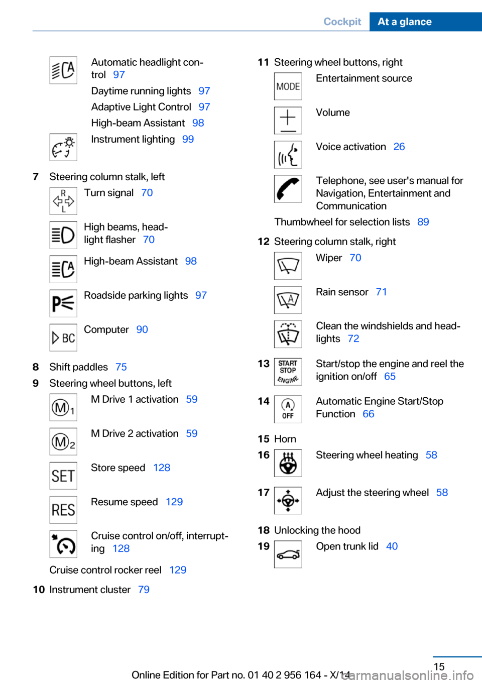
Automatic headlight con‐
trol 97
Daytime running lights 97
Adaptive Light Control 97
High-beam Assistant 98Instrument lighting 997Steering column stalk, leftTurn signal 70High beams, head‐
light flasher 70High-beam Assistant 98Roadside parking lights 97Computer 908Shift paddles 759Steering wheel buttons, leftM Drive 1 activation 59M Drive 2 activation 59Store speed 128Resume speed 129Cruise control on/off, interrupt‐
ing 128Cruise control rocker reel 12910Instrument cluster 7911Steering wheel buttons, rightEntertainment sourceVolumeVoice activation 26Telephone, see user's manual for
Navigation, Entertainment and
CommunicationThumbwheel for selection lists 8912Steering column stalk, rightWiper 70Rain sensor 71Clean the windshields and head‐
lights 7213Start/stop the engine and reel the
ignition on/off 6514Automatic Engine Start/Stop
Function 6615Horn16Steering wheel heating 5817Adjust the steering wheel 5818Unlocking the hood19Open trunk lid 40Seite 15CockpitAt a glance15
Online Edition for Part no. 01 40 2 956 164 - X/14
Page 27 of 226
Additional symbolsSymbolMeaning Spoken instructions are turned off.
Split screen
General information Additional information can be displayed on the
right side of the split screen, e.g., information
from the computer.
In the divided screen view, the so-called split
screen, this information remains visible even when you change to another menu.
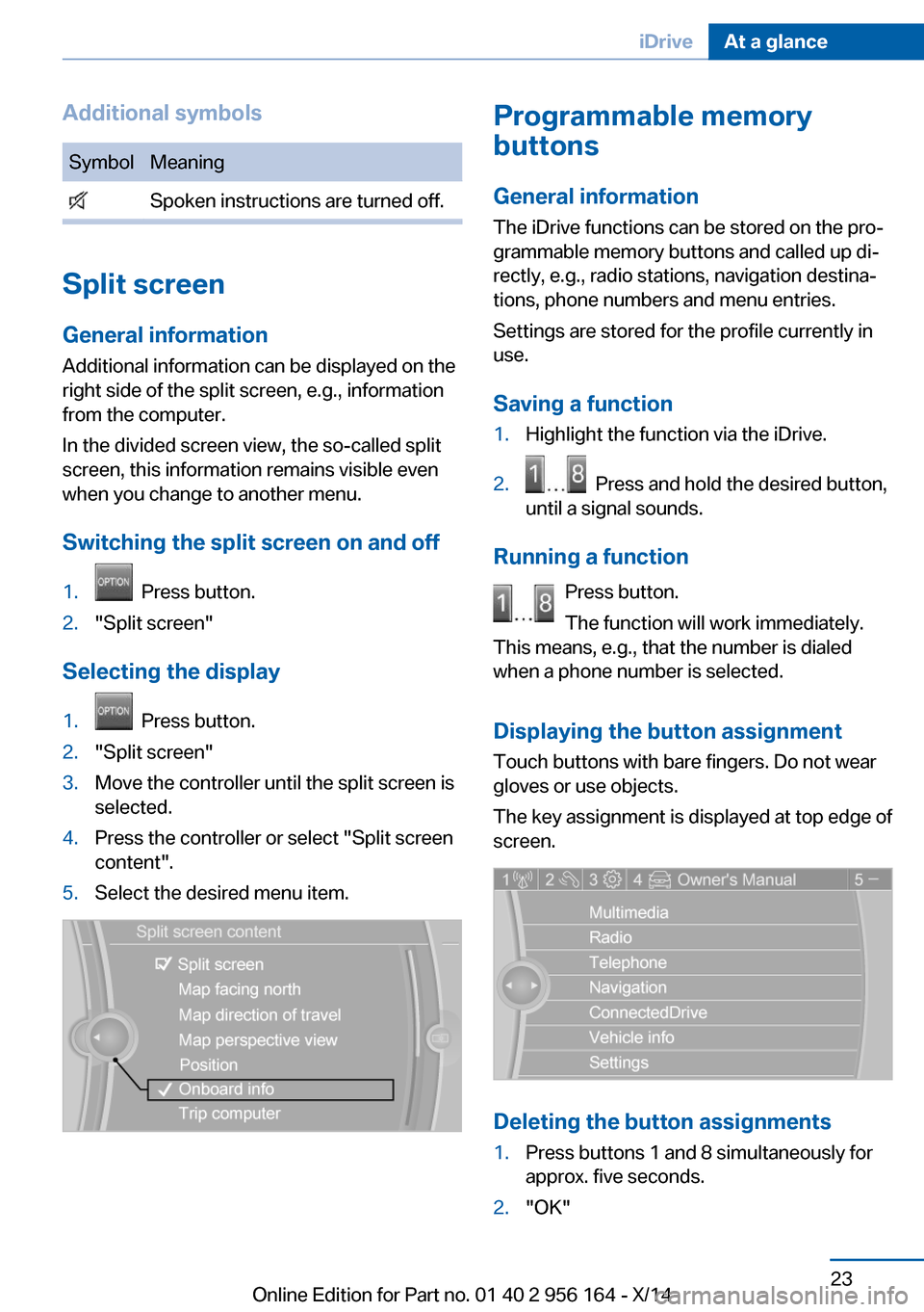
Switching the split screen on and off
1. Press button.2."Split screen"
Selecting the display
1. Press button.2."Split screen"3.Move the controller until the split screen is
selected.4.Press the controller or select "Split screen
content".5.Select the desired menu item.Programmable memory
buttons
General information
The iDrive functions can be stored on the pro‐
grammable memory buttons and called up di‐
rectly, e.g., radio stations, navigation destina‐
tions, phone numbers and menu entries.
Settings are stored for the profile currently in
use.
Saving a function1.Highlight the function via the iDrive.2. Press and hold the desired button,
until a signal sounds.
Running a function
Press button.
The function will work immediately.
This means, e.g., that the number is dialed
when a phone number is selected.
Displaying the button assignment Touch buttons with bare fingers. Do not wear
gloves or use objects.
The key assignment is displayed at top edge of
screen.
Deleting the button assignments
1.Press buttons 1 and 8 simultaneously for
approx. five seconds.2."OK"Seite 23iDriveAt a glance23
Online Edition for Part no. 01 40 2 956 164 - X/14
Page 74 of 226
Turn signal, high beams,
headlight flasher
Turn signal
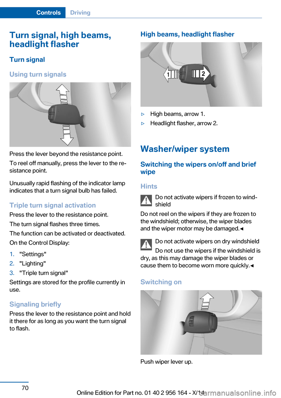
Using turn signals
Press the lever beyond the resistance point.
To reel off manually, press the lever to the re‐
sistance point.
Unusually rapid flashing of the indicator lamp
indicates that a turn signal bulb has failed.
Triple turn signal activation Press the lever to the resistance point.
The turn signal flashes three times.
The function can be activated or deactivated.
On the Control Display:
1."Settings"2."Lighting"3."Triple turn signal"
Settings are stored for the profile currently in
use.
Signaling briefly
Press the lever to the resistance point and hold
it there for as long as you want the turn signal
to flash.
High beams, headlight flasher▷High beams, arrow 1.▷Headlight flasher, arrow 2.
Washer/wiper system
Switching the wipers on/off and brief
wipe
Hints Do not activate wipers if frozen to wind‐
shield
Do not reel on the wipers if they are frozen to
the windshield; otherwise, the wiper blades
and the wiper motor may be damaged.◀
Do not activate wipers on dry windshield
Do not use the wipers if the windshield is
dry, as this may damage the wiper blades or
cause them to become worn more quickly.◀
Switching on
Push wiper lever up.
Seite 70ControlsDriving70
Online Edition for Part no. 01 40 2 956 164 - X/14
Page 86 of 226
▷Malfunction: have the system checked by
your service center.
For more information, see Tire Pressure Moni‐
tor, refer to page 104.
Steering system Steering system in some cases defec‐
tive.
Have the steering system checked by
the service center.
Engine functions Have the vehicle checked by the serv‐ice center.
For additional information, refer to On-
board Diagnostics socket, refer to page 189.
Lane departure warning System is switched on and under cer‐
tain circumstances warns if a detected
lane is left without flashing beforehand.
For additional information, refer to Lane depar‐
ture warning, refer to page 117.
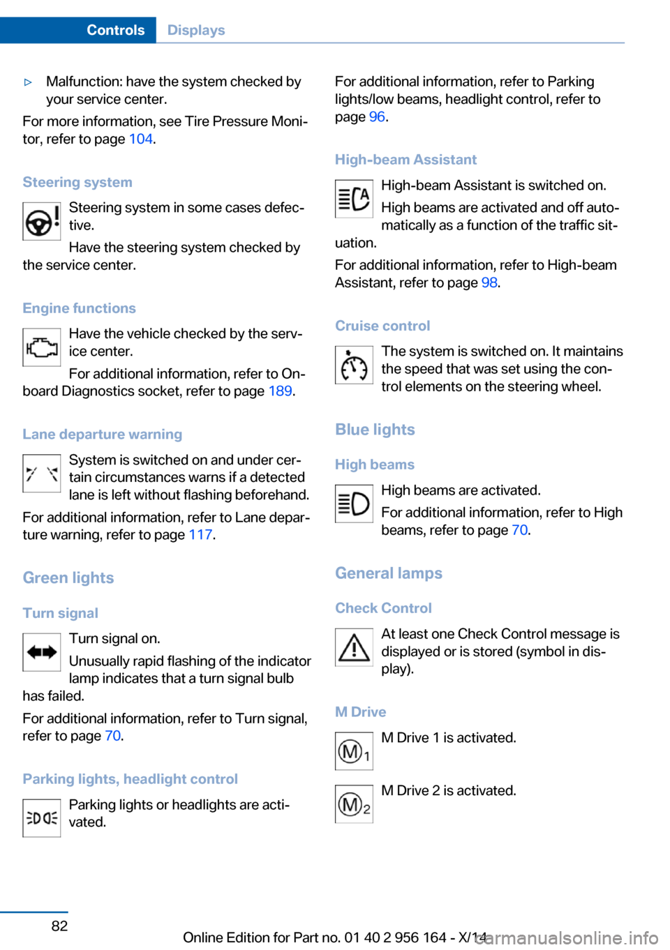
Green lights Turn signal Turn signal on.
Unusually rapid flashing of the indicator
lamp indicates that a turn signal bulb
has failed.
For additional information, refer to Turn signal,
refer to page 70.
Parking lights, headlight control Parking lights or headlights are acti‐
vated.
For additional information, refer to Parking
lights/low beams, headlight control, refer to
page 96.
High-beam Assistant High-beam Assistant is switched on.
High beams are activated and off auto‐
matically as a function of the traffic sit‐
uation.
For additional information, refer to High-beam
Assistant, refer to page 98.
Cruise control The system is switched on. It maintains
the speed that was set using the con‐
trol elements on the steering wheel.
Blue lights
High beams High beams are activated.
For additional information, refer to High
beams, refer to page 70.
General lamps
Check Control At least one Check Control message is
displayed or is stored (symbol in dis‐
play).
M Drive M Drive 1 is activated.
M Drive 2 is activated.Seite 82ControlsDisplays82
Online Edition for Part no. 01 40 2 956 164 - X/14
Page 87 of 226
Text messagesText messages in combination with a symbol
in the instrument cluster explain a Check Con‐ trol message and the meaning of the indicator
and warning lights.
Supplementary text messages
Additional information, such as on the cause of
an error or the required action, can be called up
via Check Control.
With urgent messages the added text will be
automatically displayed on the Control Display.
Symbols Depending on the Check Control message, the
following functions can be selected.▷ "Owner's Manual"
Display additional information about the
Check Control message in the Integrated
Owner's Manual.▷ "Service request"
Contact your service center.▷ "Roadside Assistance"
Contact Roadside Assistance.
Hiding Check Control messages
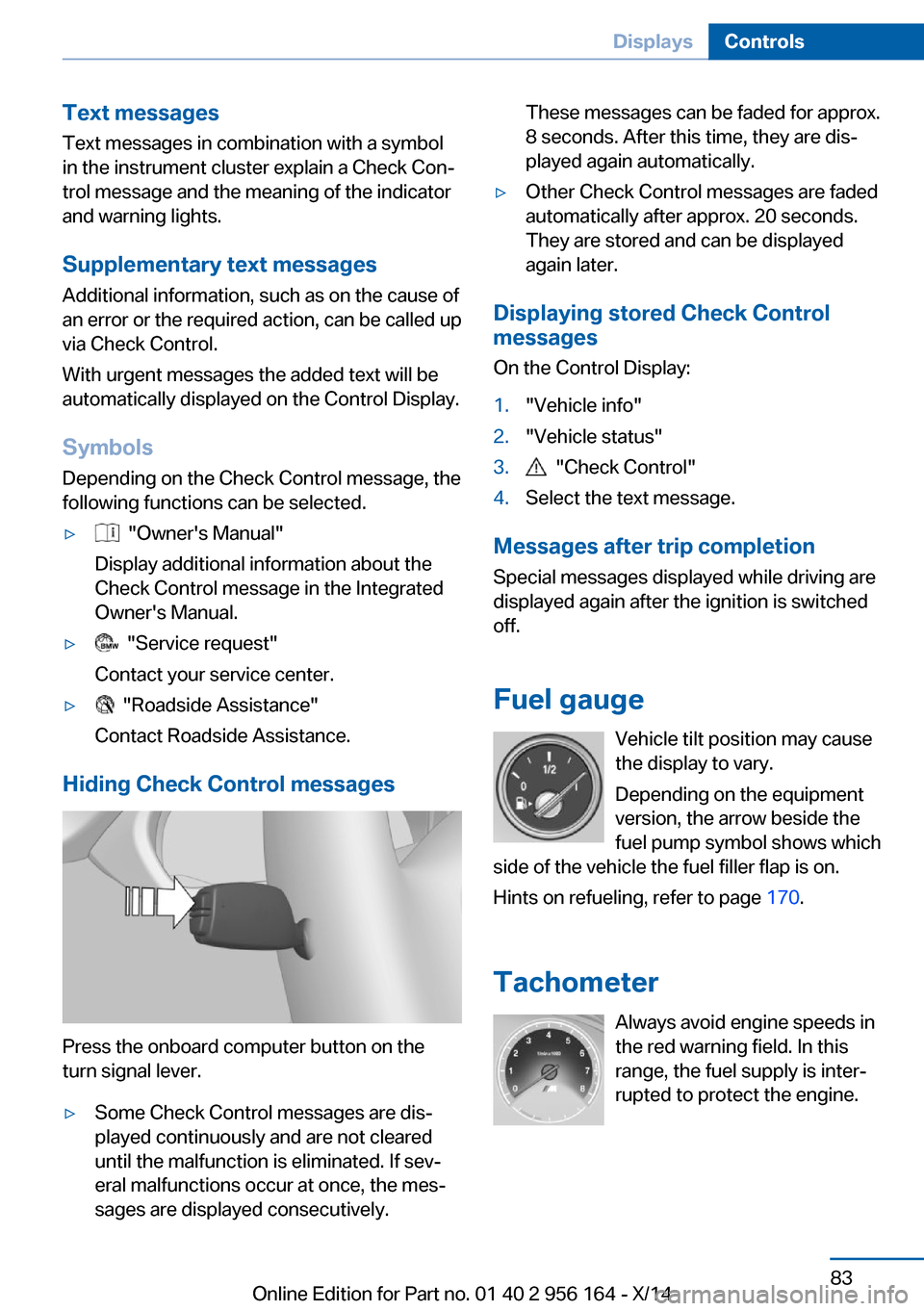
Press the onboard computer button on the
turn signal lever.
▷Some Check Control messages are dis‐
played continuously and are not cleared
until the malfunction is eliminated. If sev‐
eral malfunctions occur at once, the mes‐
sages are displayed consecutively.These messages can be faded for approx.
8 seconds. After this time, they are dis‐
played again automatically.▷Other Check Control messages are faded
automatically after approx. 20 seconds.
They are stored and can be displayed
again later.
Displaying stored Check Control
messages
On the Control Display:
1."Vehicle info"2."Vehicle status"3. "Check Control"4.Select the text message.
Messages after trip completion Special messages displayed while driving are
displayed again after the ignition is switched
off.
Fuel gauge Vehicle tilt position may cause
the display to vary.
Depending on the equipment
version, the arrow beside the
fuel pump symbol shows which
side of the vehicle the fuel filler flap is on.
Hints on refueling, refer to page 170.
Tachometer Always avoid engine speeds inthe red warning field. In this
range, the fuel supply is inter‐
rupted to protect the engine.
Seite 83DisplaysControls83
Online Edition for Part no. 01 40 2 956 164 - X/14
Page 94 of 226
Using the thumbwheel, select the desired set‐
ting and confirm it by pushing the thumbwheel.
Computer
Indication in the info display The information from the com‐
puter is shown in the info display
in the instrument cluster.
Calling up information on the info display
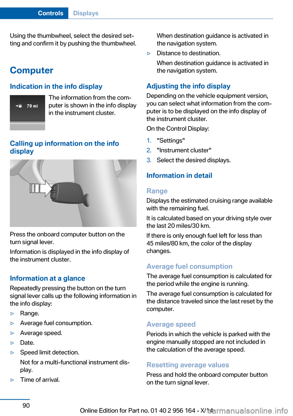
Press the onboard computer button on the
turn signal lever.
Information is displayed in the info display of
the instrument cluster.
Information at a glance
Repeatedly pressing the button on the turn
signal lever calls up the following information in
the info display:
▷Range.▷Average fuel consumption.▷Average speed.▷Date.▷Speed limit detection.
Not for a multi-functional instrument dis‐
play.▷Time of arrival.When destination guidance is activated in
the navigation system.▷Distance to destination.
When destination guidance is activated in
the navigation system.
Adjusting the info display
Depending on the vehicle equipment version,
you can select what information from the com‐
puter is to be displayed on the info display of
the instrument cluster.
On the Control Display:
1."Settings"2."Instrument cluster"3.Select the desired displays.
Information in detail
Range
Displays the estimated cruising range available
with the remaining fuel.
It is calculated based on your driving style over
the last 20 miles/30 km.
If there is only enough fuel left for less than
45 miles/80 km, the color of the display
changes.
Average fuel consumption
The average fuel consumption is calculated for
the period while the engine is running.
The average fuel consumption is calculated for
the distance traveled since the last reset by the
computer.
Average speed
Periods in which the vehicle is parked with the
engine manually stopped are not included in
the calculation of the average speed.
Resetting average values
Press and hold the onboard computer button
on the turn signal lever.
Seite 90ControlsDisplays90
Online Edition for Part no. 01 40 2 956 164 - X/14
Page 102 of 226
ActivatingPosition of switch
with the ignition
switched on.
To avoid blinding oncoming traffic, the Adap‐
tive Light Control does not swivel to the driv‐
er's side when the vehicle is at a standstill.
The turning lights are automatically switched
on depending on the steering angle or the use
of turn signals.
When driving in reverse, the turning lights may
be automatically switched on regardless of the
steering angle.
Self-leveling headlights The self-leveling headlights compensate for
acceleration and braking operations in order
not to blind the oncoming traffic and to achieve
optimum illumination of the roadway.
Malfunction A Check Control message is displayed.
Adaptive Light Control is malfunctioning or has
failed. Have the system checked as soon as
possible.
High-beam Assistant
The concept When the low beams are activated, this system
automatically switches the high beams on and
off. The procedure is controlled by a camera
on the front of the interior rearview mirror. The
assistant ensures that the high beams are acti‐
vated whenever the traffic situation allows. The
driver can intervene at any time and reel the
high beams on and off as usual.
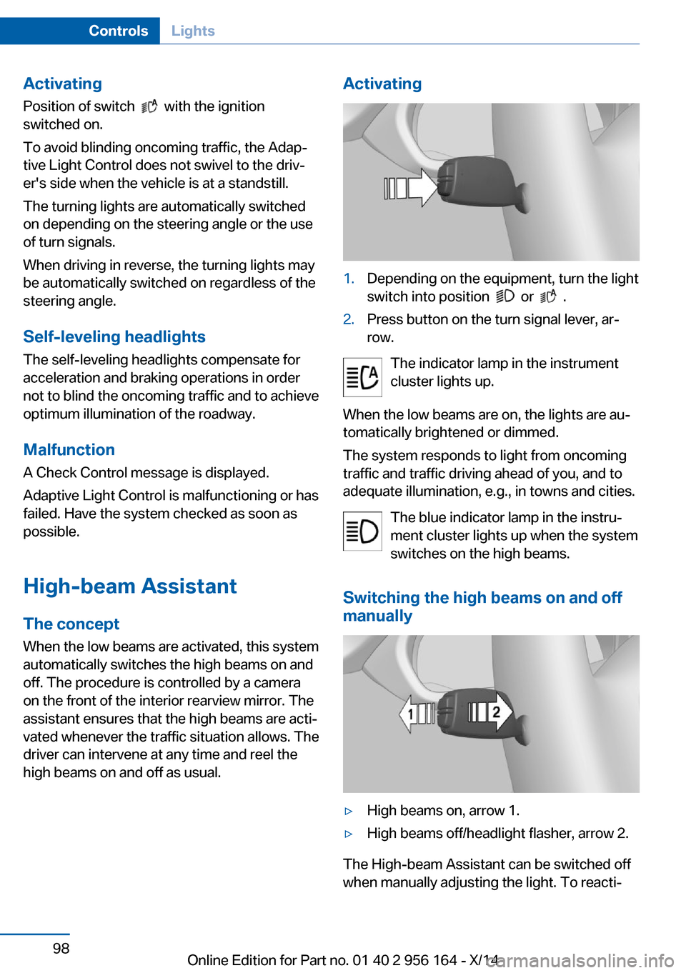
Activating1.Depending on the equipment, turn the light
switch into position
or .
2.Press button on the turn signal lever, ar‐
row.
The indicator lamp in the instrument
cluster lights up.
When the low beams are on, the lights are au‐
tomatically brightened or dimmed.
The system responds to light from oncoming
traffic and traffic driving ahead of you, and to
adequate illumination, e.g., in towns and cities.
The blue indicator lamp in the instru‐
ment cluster lights up when the system
switches on the high beams.
Switching the high beams on and off
manually
▷High beams on, arrow 1.▷High beams off/headlight flasher, arrow 2.
The High-beam Assistant can be switched off
when manually adjusting the light. To reacti‐
Seite 98ControlsLights98
Online Edition for Part no. 01 40 2 956 164 - X/14
Page 103 of 226
vate the High-beam Assistant, press the but‐
ton on the turn signal lever.
System limits Personal responsibility
The High-beam Assistant cannot serve
as a substitute for the driver's personal judg‐
ment of when to use the high beams. There‐
fore, manually reel off the high beams in situa‐
tions where required to avoid a safety risk.◀
The system is not fully functional in situations
such as the following, and driver intervention
may be necessary:▷In very unfavorable weather conditions,
such as fog or heavy precipitation.▷When detecting poorly-lit road users such
as pedestrians, cyclists, horseback riders
and wagons; when driving close to train or
ship traffic; and at animal crossings.▷In tight curves, on hilltops or in depres‐
sions, in cross traffic or half-obscured on‐
coming traffic on freeways.▷In poorly-lit towns and cities and in the
presence of highly reflective signs.▷At low speeds.▷When the windshield behind the interior
rearview mirror is fogged over, dirty or cov‐
ered with stickers, etc.
Instrument lighting
Adjusting The parking lights or low beams
must be switched on to adjust
the brightness.
Adjust the brightness with the
thumbwheel.
Interior lights
General information
The interior lights, footwell lights, access lights
and courtesy lights are controlled automati‐
cally.
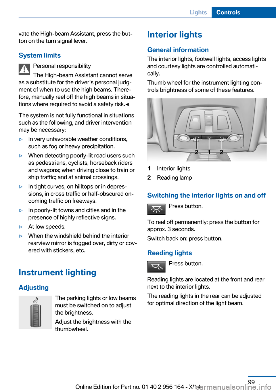
Thumb wheel for the instrument lighting con‐ trols brightness of some of these features.1Interior lights2Reading lamp
Switching the interior lights on and off
Press button.
To reel off permanently: press the button for
approx. 3 seconds.
Switch back on: press button.
Reading lights Press button.
Reading lights are located at the front and rear
next to the interior lights.
The reading lights in the rear can be adjusted
for optimal direction of the light beam.
Seite 99LightsControls99
Online Edition for Part no. 01 40 2 956 164 - X/14
Page 121 of 226
Small animals are not detected by the object
detection function, even if they are clearly visi‐
ble in the image.
Limited detection:▷People or animals who are fully or partially
covered, especially when their heads are
covered.▷People who are not in an upright position,
e.g., lying down.▷Cyclists on unconventional bicycles (e.g.,
recumbent bicycles).▷After physical damage to the system, e.g.,
after an accident.
Lane departure warning
The concept Starting at a specific speed, this system alerts
you when the vehicle on streets with lane
markings is about to leave the lane. This
speed, depending on the country version, is
between 35 mph/55 km/h and
45 mph/70 km/h.
When switching on the system below this
speed, a message is displayed in the instru‐
ment cluster.
The steering wheel begins vibrating gently in
the event of warnings. The time of the warning
may vary depending on the current driving sit‐
uation.
The system does not provide a warning if the
turn signal is set before leaving the lane.
Hints Personal responsibility
The system cannot serve as a substitute
for the driver's personal judgment of the
course of the road and the traffic situation.
In the event of a warning, do not jerk the steer‐
ing wheel, as you may lose control of the vehi‐
cle.◀
At a glance
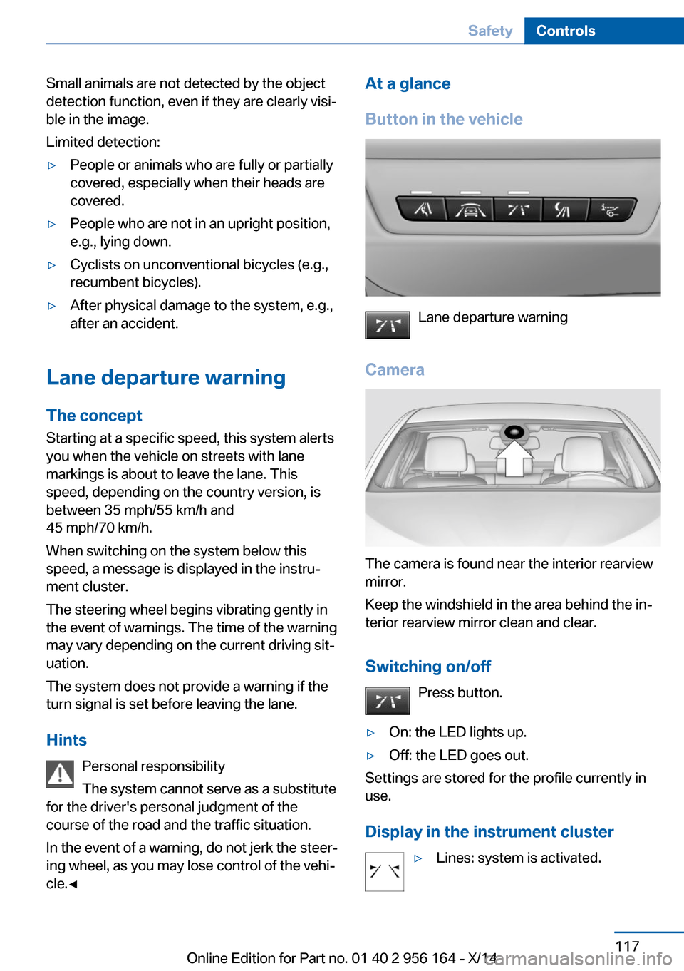
Button in the vehicle
Lane departure warning
Camera
The camera is found near the interior rearview
mirror.
Keep the windshield in the area behind the in‐
terior rearview mirror clean and clear.
Switching on/off Press button.
▷On: the LED lights up.▷Off: the LED goes out.
Settings are stored for the profile currently in
use.
Display in the instrument cluster
▷Lines: system is activated.Seite 117SafetyControls117
Online Edition for Part no. 01 40 2 956 164 - X/14
Page 122 of 226
▷Arrows: at least one lane marking was de‐
tected and warnings can be issued.
Issued warning
If you leave the lane and if a lane marking has
been detected, the steering wheel begins vi‐
brating.
If the turn signal is set before changing the
lane, a warning is not issued.
End of warning
The warning ends:
▷Automatically after approx. 3 seconds.▷When returning to your own lane.▷When braking hard.▷When using the turn signal.
System limits
The system may not be fully functional in the
following situations:
▷In heavy fog, rain or snowfall.▷In the event of missing, worn, poorly visi‐
ble, merging, diverging, or multiple lane
markings such as in construction areas.▷When lane markings are covered in snow,
ice, dirt or water.▷In tight curves or on narrow lanes.▷When the lane markings are covered by
objects.▷When driving very close to the vehicle in
front of you.▷When driving toward bright lights.▷When the windshield in front of the interior
rearview mirror is fogged over, dirty or cov‐
ered with stickers, etc.▷During calibration of the camera immedi‐
ately after vehicle shipment.Active Blind Spot Detection
The concept
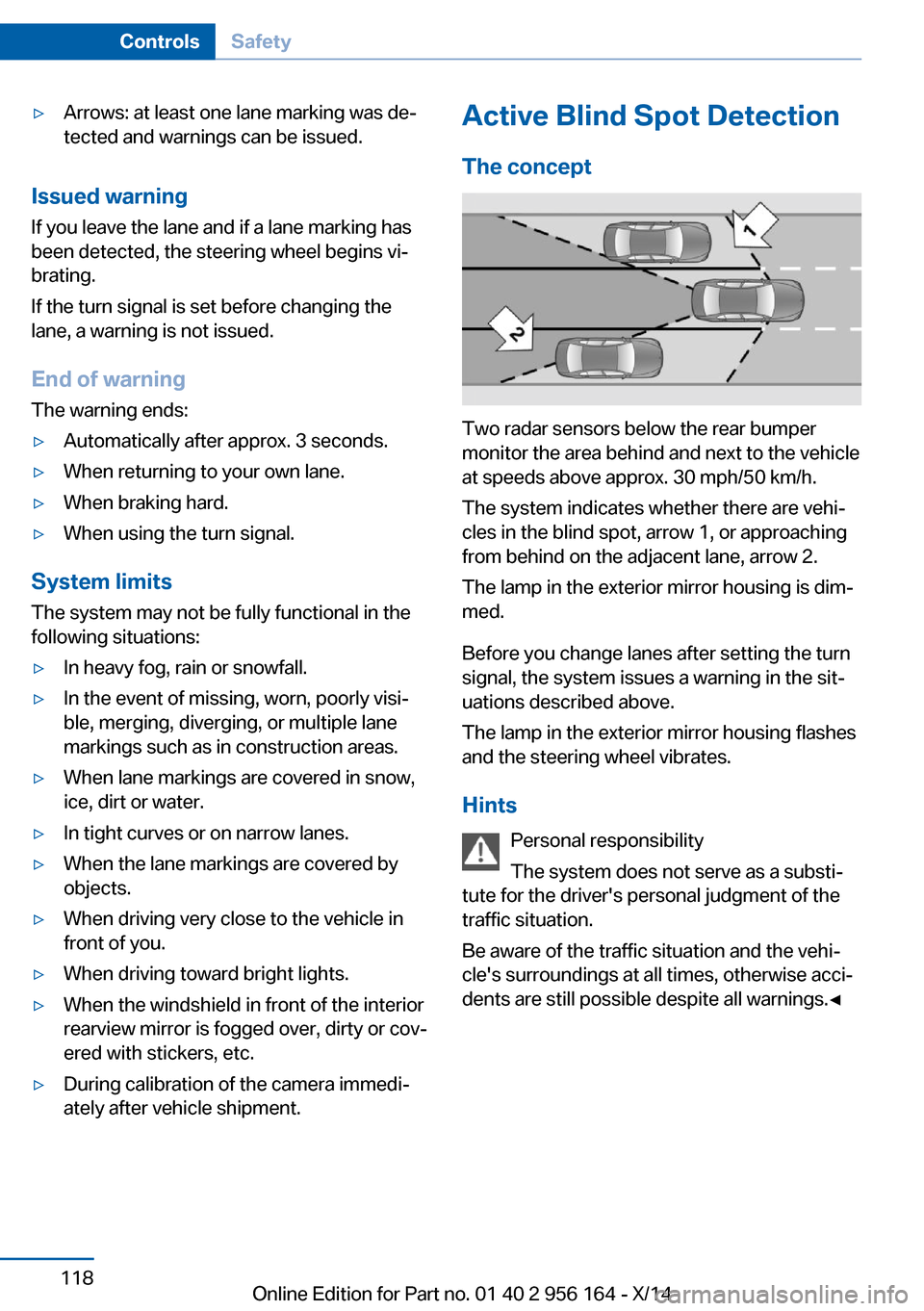
Two radar sensors below the rear bumper
monitor the area behind and next to the vehicle
at speeds above approx. 30 mph/50 km/h.
The system indicates whether there are vehi‐
cles in the blind spot, arrow 1, or approaching
from behind on the adjacent lane, arrow 2.
The lamp in the exterior mirror housing is dim‐
med.
Before you change lanes after setting the turn
signal, the system issues a warning in the sit‐
uations described above.
The lamp in the exterior mirror housing flashes
and the steering wheel vibrates.
Hints Personal responsibility
The system does not serve as a substi‐
tute for the driver's personal judgment of the
traffic situation.
Be aware of the traffic situation and the vehi‐
cle's surroundings at all times, otherwise acci‐
dents are still possible despite all warnings.◀
Seite 118ControlsSafety118
Online Edition for Part no. 01 40 2 956 164 - X/14