steering wheel BMW M6 GRAN COUPE 2015 F06M Owner's Guide
[x] Cancel search | Manufacturer: BMW, Model Year: 2015, Model line: M6 GRAN COUPE, Model: BMW M6 GRAN COUPE 2015 F06MPages: 226, PDF Size: 4.76 MB
Page 106 of 226
Knee airbagThe knee airbag supports the legs in a frontal
impact.
Protective action
Airbags are not triggered in every impact situa‐
tion, e.g., in less severe accidents or rear-end
collisions.
Information on how to ensure the optimal
protective effect of the airbags▷Keep at a distance from the airbags.▷Always grasp the steering wheel on the
steering wheel rim, holding your hands at
the 3 o'clock and 9 o'clock positions, to
keep the risk of injury to your hands or
arms as low as possible when the airbag is
triggered.▷There should be no person, animals, or ob‐
jects between an airbag and a person.▷Do not use the cover of the front airbag on
the front passenger side as a storage area.▷Dashboard and windshield on the front
passenger side must stay clear - do not at‐
tach adhesive labels or coverings and do
not attach brackets or cables, e. g., for GPS
devices or' mobile phones.▷Make sure that the front passenger is sit‐
ting correctly, i.e., keeps his or her feet and
legs in the footwell; otherwise, leg injuries
might occur when front airbag is activated.▷Do not place slip covers, seat cushions or
other objects on the front passenger seat
that are not approved specifically for seats
with integrated side airbags.▷Do not hang pieces of clothing, such as
jackets, over the backrests.▷Make sure that occupants keep their heads
away from the side airbag and do not rest
against the head airbag; otherwise, injuries
might occur when airbag is activated.▷Do not remove the airbag system.▷Do not remove the steering wheel.▷Do not apply adhesive materials to the air‐
bag cover panels, do not cover them or
modify them in any way.▷Never modify either the individual compo‐
nents or the wiring in the airbag system.
This also applies to steering wheel covers,
the dashboard, the seats, the roof pillars
and the sides of the roofliner.◀
Even when you follow all instructions very
closely, injury from contact with the airbags
cannot be ruled out in certain situations.
The ignition and inflation noise may lead to
short-term and, in most cases, temporary
hearing impairment in sensitive individuals.
Malfunction, deactivation and after de‐
ploying the airbags
Do not touch the individual components imme‐
diately after the system has been triggered;
otherwise, you may risk burns.
Only have the airbags checked, repaired or dis‐
mantled and the airbag generator scrapped by
the service center or an authorized repair shop
for handling explosives.
Non-professional attempts to service the sys‐
tem could lead to failure in an emergency or
unintentional activation of the airbag - both
may lead to injury.◀
Warnings and information on the airbags are also found on the sun visors.
Functional readiness of the airbag
system
When the ignition is reel on, the warn‐
ing lamp in the instrument cluster lights
up briefly and thereby indicates the op‐
erational readiness of the entire airbag system
and the belt tensioner.
Airbag system malfunctioning
▷Warning lamp does not come on when the
ignition is turned on.▷The warning lamp lights up continuously.Seite 102ControlsSafety102
Online Edition for Part no. 01 40 2 954 258 - II/15
Page 109 of 226
Status control displayTire and system status are indicated by the
color of the wheels and a text message on the
Control Display.
All wheels green System is active and will issue a warning rela‐
tive to the tire inflation pressures stored during
the last reset.
One wheel is yellow A flat tire or major drop in inflation pressure in
the indicated tire.
All wheels are yellow A flat tire or major drop in inflation pressure in
several tires.
Wheels, gray The system cannot detect a flat tire. Reasons
for this may be:▷The system is being reset.▷Malfunction.
Status information
The status control display additionally shows
the current tire inflation pressures and, de‐
pending on the model, tire temperatures. It
shows the actual values read; they may vary depending on driving style or weather condi‐
tions.
Carry out reset Reset the system after each adjustment of the
tire inflation pressure and after every tire or
wheel change.
On the Control Display and on the vehicle:
1."Vehicle info"2."Vehicle status"3. "Perform reset"4.Start the engine - do not drive off.5.Reset tire inflation pressure:"Perform
reset".6.Drive away.
The tires are shown in gray and the status is
displayed.
After driving faster than 19 mph/30 km/h for a
short period, the set tire inflation pressures are
accepted as reference values. The reset is
completed automatically while driving.
After a successfully completed Reset, the
wheels on the Control Display are shown in
green and "Tire Pressure Monitor (TPM)
active" is displayed.
You may interrupt this trip at any time. When
you continue the reset resumes automatically.
Low tire pressure message The yellow warning lamp lights up. A
Check Control message is displayed.
▷There is a flat tire or a major loss in
tire inflation pressure.▷No reset was performed for the system.
The system therefore issues a warning
based on the tire inflation pressures before
the last reset.1.Reduce your speed and stop cautiously.
Avoid sudden braking and steering maneu‐
vers.2.Identify the damaged wheel. Do so by
checking the tire inflation pressure using
the Mobility System. To correct the tire in‐
flation pressure3.Repair flat tire with the Mobility System or
replace the damaged wheel.
Required tire inflation pressure check
message
A Check Control message is displayed in the
following situations
▷The system has detected a wheel change,
but no reset was done.Seite 105SafetyControls105
Online Edition for Part no. 01 40 2 954 258 - II/15
Page 111 of 226
that prevent the TPMS from functioning prop‐
erly. Always check the TPMS malfunction tell‐
tale after replacing one or more tires or wheels
on your vehicle to ensure that the replacement
or alternate tires and wheels allow the TPMS
to continue to function properly.
FTM Flat Tire Monitor The conceptThe system detects tire inflation pressure losson the basis of rotation speed differences be‐
tween the individual wheels while driving.
In the event of a tire inflation pressure loss, the
diameter and therefore the rotational speed of
the corresponding wheel changes. This will be
detected and reported as a flat tire.
The system does not measure the actual infla‐
tion pressure in the tires.
Functional requirements
The system must have been initialized when
the tire inflation pressure was correct; other‐
wise, reliable flagging of a flat tire is not as‐
sured. Initialize the system after each correc‐ tion of the tire inflation pressure and after
every tire or wheel change.
Status display
The current status of the Flat Tire Monitor can
be displayed on the Control Display, e.g.,
whether or not the FTM is active.
On the Control Display:1."Vehicle info"2."Vehicle status"3. "Flat Tire Monitor (FTM)"
The status is displayed.
Initialization
When initializing the once set inflation tire
pressures serve as reference values in order to
detect a flat tire. Initialization is started by con‐
firming the tire inflation pressures.
Do not initialize the system when driving with
snow chains.
On the Control Display:1."Vehicle info"2."Vehicle status"3. "Perform reset"4.Start the engine - do not drive off.5.Start the initialization with "Perform reset".6.Drive away.
The initialization is completed while driving,
which can be interrupted at any time.
The initialization automatically continues when
driving resumes.
Indication of a flat tire The yellow warning lamp lights up. A
Check Control message is displayed.
There is a flat tire or a major loss in tire
inflation pressure.
1.Reduce your speed and stop cautiously.
Avoid sudden braking and steering maneu‐
vers.2.Identify the damaged wheel. Do so by
checking the tire inflation pressure using
the Mobility System. If the tire inflation
pressure in all tires is correct, the Flat Tire
Monitor may not have been initialized. In
this case, initialize the system.3.Repair flat tire with the Mobility System or
replace the damaged wheel.
System limits
Sudden tire damage
Sudden serious tire damage caused by
external circumstances cannot be recognized
in advance.◀
Seite 107SafetyControls107
Online Edition for Part no. 01 40 2 954 258 - II/15
Page 115 of 226
Acute warnings can also be triggered without
previous prewarning.
Braking intervention The warning prompts the driver himself/herself
to react. During a warning, the maximum brak‐
ing force is used. Premise for the brake boos‐
ter is sufficiently quick and hard stepping on
the brake pedal. The system can assist with
some braking intervention if there is risk of a
collision. At low speeds vehicles may thus
come to a complete stop.
Manual transmission: During a braking inter‐
vention up to a complete stop, the engine may
be shut down.
The braking intervention is executed only if
DSC Dynamic Stability Control is switched on
and M Dynamic mode MDM is not activated.
The braking intervention can be interrupted by
stepping on the accelerator pedal or by ac‐
tively moving the steering wheel.
Object detection can be restricted. Limitations
of the detection range and functional restric‐
tions are to be considered.
System limits
Detection range
The system's detection potential is limited.
Thus a warning might not be issued or be is‐
sued late.
E. g. the following situations may not be de‐
tected:▷Slow moving vehicles when you approach
them at high speed.▷Vehicles that suddenly swerve in front of
you, or sharply decelerating vehicles.▷Vehicles with an unusual rear appearance.▷Two-wheeled vehicles ahead of you.
Functional limitations
The system may not be fully functional in the
following situations:
▷In heavy fog, rain, sprayed water or snow‐
fall.▷In tight curves.▷If the driving stability control systems are
limited or deactivated, e.g., DSC OFF.▷If, depending on the vehicle equipment
version, the field of view of the camera in
the mirror or the radar sensor is dirty or ob‐
scured.▷Up to 10 seconds after the start of the en‐
gine, via the Start/Stop knob.▷During calibration of the camera immedi‐
ately after vehicle shipment.▷If there is constant blinding effects be‐
cause of oncoming light, e. g., from the sun
low in the sky.
Warning sensitivity
The more sensitive the warning settings are,
e.g. the warning time, the more warnings are
displayed. However, there may also be an ex‐
cess of false warnings.
Pedestrian warning
Depending on how the vehicle is equipped, the
function warns of an imminent collision with
pedestrians during daytime or nighttime.
The function is subdivided into the following
systems:
▷During daytime: Pedestrian warning with
city braking function, refer to page 111▷At night: Night vision, refer to page 114
Pedestrian warning with city
braking function
The concept The ystem can help prevent accidents with pe‐
destrians.
Seite 111SafetyControls111
Online Edition for Part no. 01 40 2 954 258 - II/15
Page 117 of 226
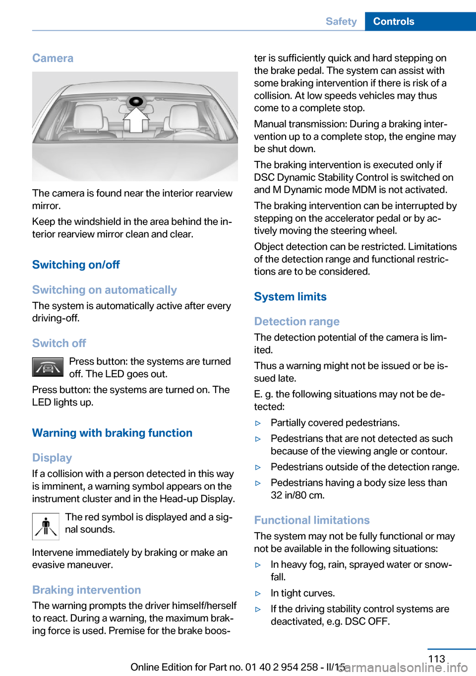
Camera
The camera is found near the interior rearview
mirror.
Keep the windshield in the area behind the in‐
terior rearview mirror clean and clear.
Switching on/off
Switching on automatically The system is automatically active after every
driving-off.
Switch off Press button: the systems are turned
off. The LED goes out.
Press button: the systems are turned on. The
LED lights up.
Warning with braking function
Display
If a collision with a person detected in this way
is imminent, a warning symbol appears on the
instrument cluster and in the Head-up Display.
The red symbol is displayed and a sig‐
nal sounds.
Intervene immediately by braking or make an
evasive maneuver.
Braking intervention The warning prompts the driver himself/herself
to react. During a warning, the maximum brak‐
ing force is used. Premise for the brake boos‐
ter is sufficiently quick and hard stepping on
the brake pedal. The system can assist with
some braking intervention if there is risk of a
collision. At low speeds vehicles may thus
come to a complete stop.
Manual transmission: During a braking inter‐
vention up to a complete stop, the engine may
be shut down.
The braking intervention is executed only if
DSC Dynamic Stability Control is switched on
and M Dynamic mode MDM is not activated.
The braking intervention can be interrupted by
stepping on the accelerator pedal or by ac‐
tively moving the steering wheel.
Object detection can be restricted. Limitations
of the detection range and functional restric‐
tions are to be considered.
System limits
Detection range
The detection potential of the camera is lim‐
ited.
Thus a warning might not be issued or be is‐
sued late.
E. g. the following situations may not be de‐
tected:▷Partially covered pedestrians.▷Pedestrians that are not detected as such
because of the viewing angle or contour.▷Pedestrians outside of the detection range.▷Pedestrians having a body size less than
32 in/80 cm.
Functional limitations
The system may not be fully functional or may
not be available in the following situations:
▷In heavy fog, rain, sprayed water or snow‐
fall.▷In tight curves.▷If the driving stability control systems are
deactivated, e.g. DSC OFF.Seite 113SafetyControls113
Online Edition for Part no. 01 40 2 954 258 - II/15
Page 121 of 226
Limits of pedestrian and animal
detection
In some situations, it may occur that pedes‐
trians are detected as animals or animals as
pedestrians.
Small animals are not detected by the object
detection function, even if they are clearly visi‐
ble in the image.
Limited detection:▷People or animals who are fully or partially
covered, especially when their heads are
covered.▷People who are not in an upright position,
e.g., lying down.▷Cyclists on unconventional bicycles (e.g.,
recumbent bicycles).▷After physical damage to the system, e.g.,
after an accident.
Lane departure warning
The concept Starting at a specific speed, this system alerts
you when the vehicle on streets with lane
markings is about to leave the lane. This
speed, depending on the country version, is
between 35 mph/55 km/h and
45 mph/70 km/h.
When switching on the system below this
speed, a message is displayed in the instru‐
ment cluster.
The steering wheel begins vibrating gently in
the event of warnings. The time of the warning
may vary depending on the current driving sit‐
uation.
The system does not provide a warning if the
turn signal is set before leaving the lane.
Hints
Personal responsibility
The system cannot serve as a substitute
for the driver's personal judgment of the
course of the road and the traffic situation.
In the event of a warning, do not jerk the steer‐
ing wheel, as you may lose control of the vehi‐
cle.◀
At a glance
Button in the vehicle
Lane departure warning
Camera
The camera is found near the interior rearview
mirror.
Keep the windshield in the area behind the in‐
terior rearview mirror clean and clear.
Switching on/off Press button.
Seite 117SafetyControls117
Online Edition for Part no. 01 40 2 954 258 - II/15
Page 122 of 226
▷On: the LED lights up.▷Off: the LED goes out.
Settings are stored for the profile currently in
use.
Display in the instrument cluster
▷Lines: system is activated.▷Arrows: at least one lane marking
was detected and warnings can be
issued.
Issued warning
If you leave the lane and if a lane marking has
been detected, the steering wheel begins vi‐
brating.
If the turn signal is set before changing the
lane, a warning is not issued.
End of warning
The warning ends:
▷Automatically after approx. 3 seconds.▷When returning to your own lane.▷When braking hard.▷When using the turn signal.
System limits
The system may not be fully functional in the
following situations:
▷In heavy fog, rain or snowfall.▷In the event of missing, worn, poorly visi‐
ble, merging, diverging, or multiple lane
markings such as in construction areas.▷When lane markings are covered in snow,
ice, dirt or water.▷In tight curves or on narrow lanes.▷When the lane markings are covered by
objects.▷When driving very close to the vehicle in
front of you.▷When driving toward bright lights.▷When the windshield in front of the interior
rearview mirror is fogged over, dirty or cov‐
ered with stickers, etc.▷During calibration of the camera immedi‐
ately after vehicle shipment.
Active Blind Spot Detection
The concept
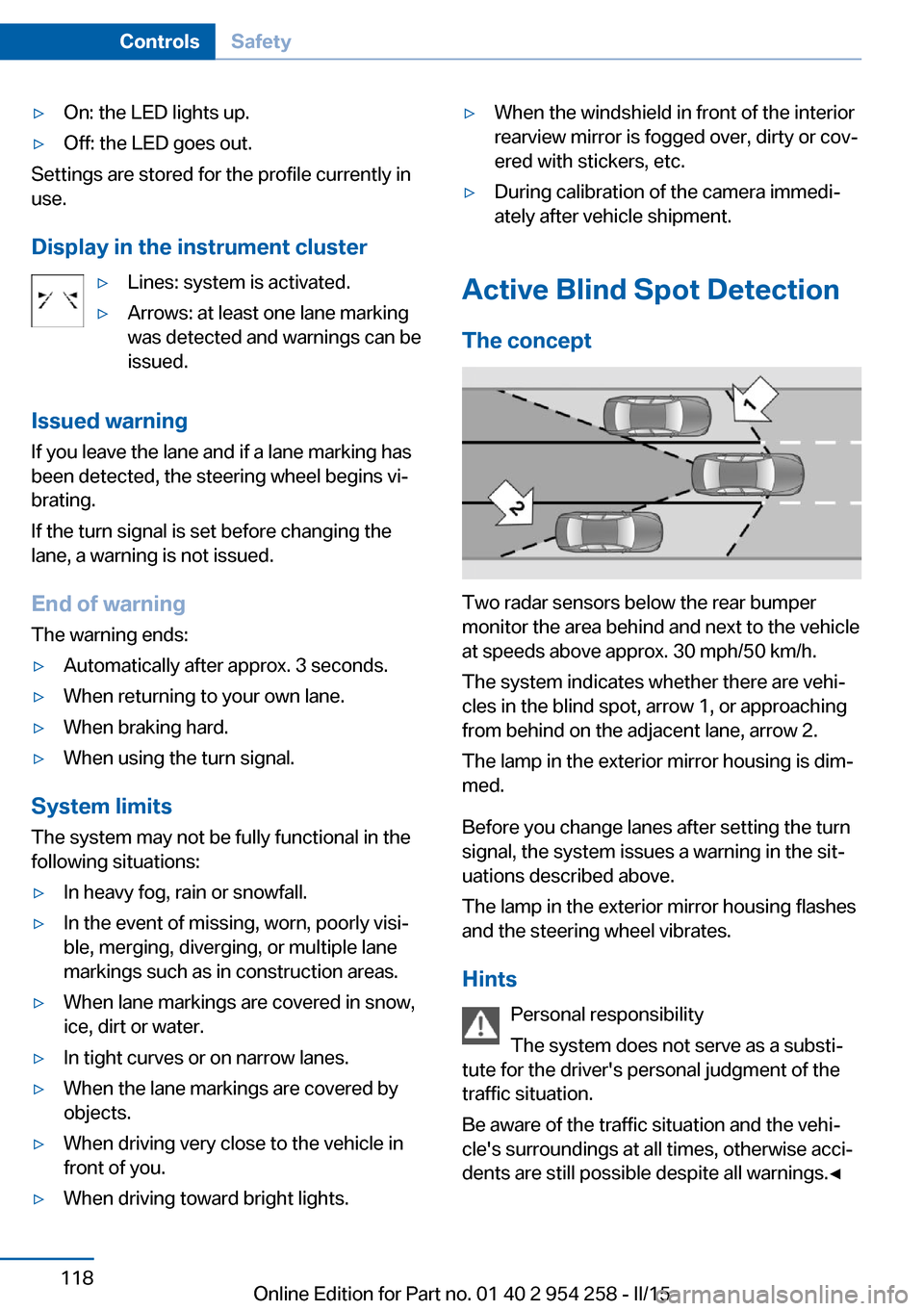
Two radar sensors below the rear bumper
monitor the area behind and next to the vehicle
at speeds above approx. 30 mph/50 km/h.
The system indicates whether there are vehi‐
cles in the blind spot, arrow 1, or approaching
from behind on the adjacent lane, arrow 2.
The lamp in the exterior mirror housing is dim‐
med.
Before you change lanes after setting the turn
signal, the system issues a warning in the sit‐
uations described above.
The lamp in the exterior mirror housing flashes
and the steering wheel vibrates.
Hints Personal responsibility
The system does not serve as a substi‐
tute for the driver's personal judgment of the
traffic situation.
Be aware of the traffic situation and the vehi‐
cle's surroundings at all times, otherwise acci‐
dents are still possible despite all warnings.◀
Seite 118ControlsSafety118
Online Edition for Part no. 01 40 2 954 258 - II/15
Page 123 of 226
At a glance
Button in the vehicle
Active Blind Spot Detection
Radar sensors
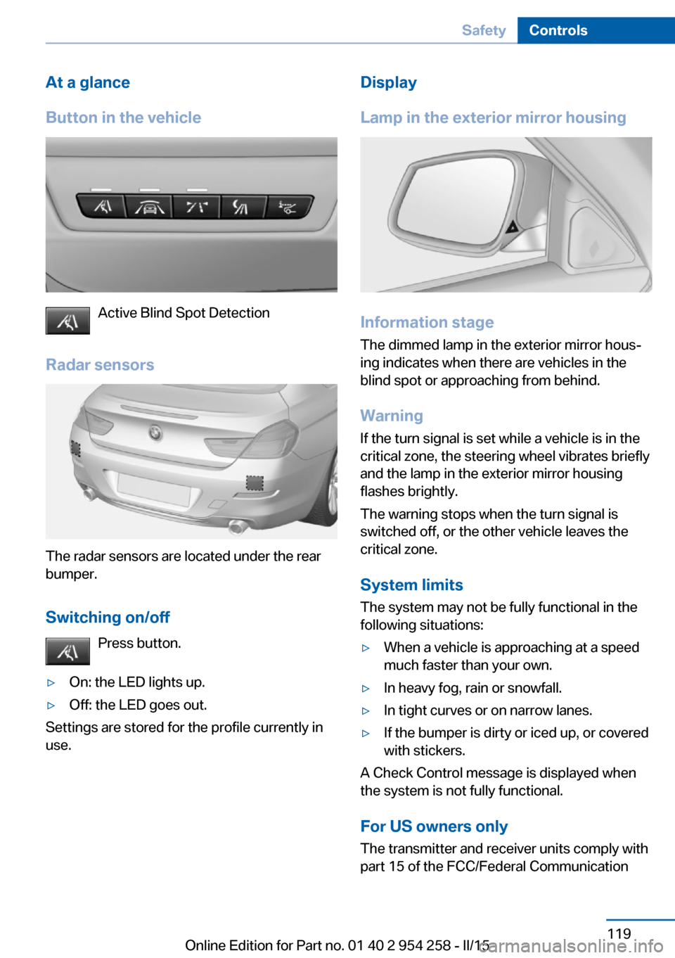
The radar sensors are located under the rear
bumper.
Switching on/off Press button.
▷On: the LED lights up.▷Off: the LED goes out.
Settings are stored for the profile currently in
use.
Display
Lamp in the exterior mirror housing
Information stage
The dimmed lamp in the exterior mirror hous‐
ing indicates when there are vehicles in the
blind spot or approaching from behind.
Warning If the turn signal is set while a vehicle is in the
critical zone, the steering wheel vibrates briefly
and the lamp in the exterior mirror housing
flashes brightly.
The warning stops when the turn signal is
switched off, or the other vehicle leaves the
critical zone.
System limits
The system may not be fully functional in the
following situations:
▷When a vehicle is approaching at a speed
much faster than your own.▷In heavy fog, rain or snowfall.▷In tight curves or on narrow lanes.▷If the bumper is dirty or iced up, or covered
with stickers.
A Check Control message is displayed when
the system is not fully functional.
For US owners only The transmitter and receiver units comply with
part 15 of the FCC/Federal Communication
Seite 119SafetyControls119
Online Edition for Part no. 01 40 2 954 258 - II/15
Page 127 of 226
Driving stability control systemsVehicle features and optionsThis chapter describes all standard, country-
specific and optional features offered with the
series. It also describes features that are not
necessarily available in your car, e. g., due to
the selected options or country versions. This
also applies to safety-related functions and
systems. The respectively applicable country
provisions must be observed when using the
respective features and systems.
Antilock Brake System ABS ABS prevents locking of the wheels during
braking.
The vehicle contains its steering power even
during full brake applications, thus increasing
active safety.
ABS is operational every time you start the en‐
gine.
Brake assistant When you apply the brakes rapidly, this system
automatically produces the greatest possible
braking force boost. It reduces the braking dis‐
tance to a minimum during emergency stop.
This system utilizes all of the benefits provided
by ABS.
Do not reduce the pressure on the brake pedal
for the duration of the emergency stop.
Drive-off assistant This system supports driving off on inclines.
The parking brake is not required.1.Hold the vehicle in place with the foot
brake.2.Release the foot brake and drive off with‐
out delay.
After the foot brake is released, the vehicle is
held in place for approx. 2 seconds.
Depending on the vehicle load, the vehicle may
roll back slightly.
Driving off without delay
After releasing the foot brake, start driv‐
ing without delay, since the drive-off assistant
will not hold the vehicle in place for more than
approx. 2 seconds and the vehicle will begin to
roll back.◀
M Drive The conceptIndividual settings can be carried out in twopreassigned configurations for the vehicle.
When the engine is started, an efficient driving
state is active by default. M Drive is deacti‐
vated.
At a glance
Configurations The configurations are preassigned as follows:
▷"M Drive 1": relaxed, comfortable driving.▷"M Drive 2": sporty, dynamic driving.
Setting options
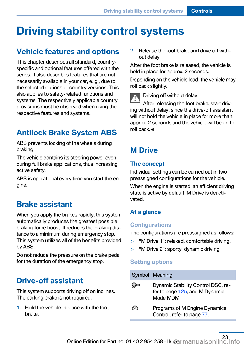
SymbolMeaning Dynamic Stability Control DSC, re‐
fer to page 125, and M Dynamic
Mode MDM. Programs of M Engine Dynamics
Control, refer to page 77.Seite 123Driving stability control systemsControls123
Online Edition for Part no. 01 40 2 954 258 - II/15
Page 129 of 226
DSC Dynamic Stability
Control
The concept DSC prevents traction loss in the power
wheels when driving off and accelerating.
DSC also recognizes unstable vehicle condi‐
tions such as fishtailing or nose-diving. Within
the physical limits DSC helps to keep the vehi‐
cle on a steady course by reducing engine
speed and by applying brakes to the individual
wheels.
Note Adjust your driving style to the situation
An appropriate driving style is always the
responsibility of the driver.
The laws of physics cannot be repealed, not
even with DSC.
Therefore, do not reduce the additional safety
margin by driving in a risky manner.◀
Do not deactivate DSC when driving with
roof load
Do not deactivate Dynamic Stability Control
DSC when driving with roof load, e.g. roof-
mounted luggage rack.
Otherwise, driving safety is not given in driv‐
ing-critical situation due to the elevated center
of gravity.◀
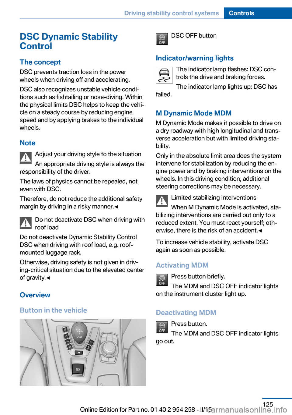
Overview
Button in the vehicleDSC OFF button
Indicator/warning lights The indicator lamp flashes: DSC con‐
trols the drive and braking forces.
The indicator lamp lights up: DSC has
failed.
M Dynamic Mode MDM
M Dynamic Mode makes it possible to drive on
a dry roadway with high longitudinal and trans‐
verse acceleration but with limited driving sta‐
bility.
Only in the absolute limit area does the system
intervene for stabilization by reducing the en‐
gine power and by braking interventions on the
wheels. In this driving condition, additional
steering corrections may be necessary.
Limited stabilizing interventions
When M Dynamic Mode is activated, sta‐
bilizing interventions are carried out only to a
reduced extent. You must react yourself; oth‐
erwise, there is the risk of an accident.◀
To increase vehicle stability, activate DSC
again as soon as possible.
Activating MDM Press button briefly.
The MDM and DSC OFF indicator lights
on the instrument cluster light up.
Deactivating MDM Press button.
The MDM and DSC OFF indicator lights
go out.Seite 125Driving stability control systemsControls125
Online Edition for Part no. 01 40 2 954 258 - II/15