service indicator BMW M6 GRAN COUPE 2015 F06M Owner's Manual
[x] Cancel search | Manufacturer: BMW, Model Year: 2015, Model line: M6 GRAN COUPE, Model: BMW M6 GRAN COUPE 2015 F06MPages: 226, PDF Size: 4.76 MB
Page 84 of 226
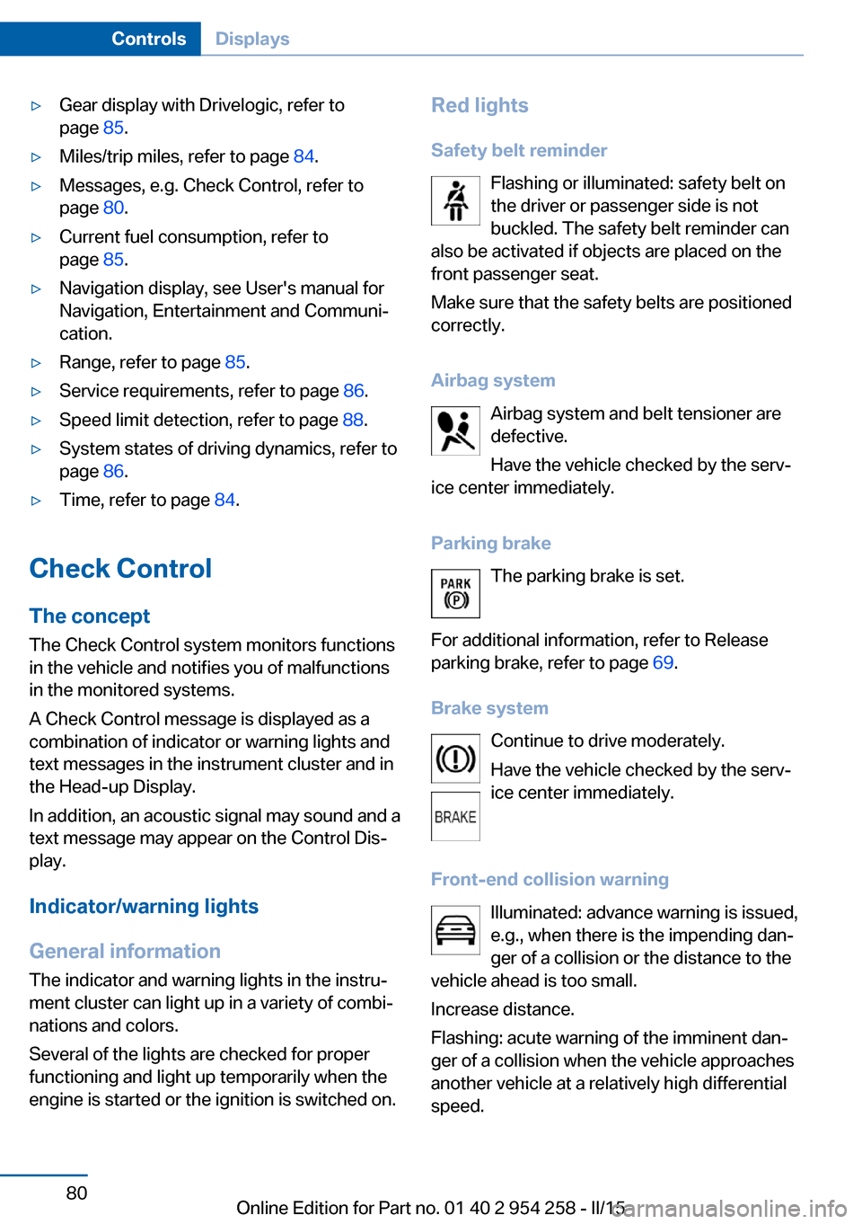
▷Gear display with Drivelogic, refer to
page 85.▷Miles/trip miles, refer to page 84.▷Messages, e.g. Check Control, refer to
page 80.▷Current fuel consumption, refer to
page 85.▷Navigation display, see User's manual for
Navigation, Entertainment and Communi‐
cation.▷Range, refer to page 85.▷Service requirements, refer to page 86.▷Speed limit detection, refer to page 88.▷System states of driving dynamics, refer to
page 86.▷Time, refer to page 84.
Check Control
The concept The Check Control system monitors functions
in the vehicle and notifies you of malfunctions
in the monitored systems.
A Check Control message is displayed as a
combination of indicator or warning lights and
text messages in the instrument cluster and in
the Head-up Display.
In addition, an acoustic signal may sound and a text message may appear on the Control Dis‐
play.
Indicator/warning lights
General information
The indicator and warning lights in the instru‐
ment cluster can light up in a variety of combi‐
nations and colors.
Several of the lights are checked for proper
functioning and light up temporarily when the
engine is started or the ignition is switched on.
Red lights
Safety belt reminder Flashing or illuminated: safety belt on
the driver or passenger side is not
buckled. The safety belt reminder can
also be activated if objects are placed on the
front passenger seat.
Make sure that the safety belts are positioned
correctly.
Airbag system Airbag system and belt tensioner are
defective.
Have the vehicle checked by the serv‐
ice center immediately.
Parking brake The parking brake is set.
For additional information, refer to Release
parking brake, refer to page 69.
Brake system Continue to drive moderately.
Have the vehicle checked by the serv‐
ice center immediately.
Front-end collision warning Illuminated: advance warning is issued,
e.g., when there is the impending dan‐
ger of a collision or the distance to the
vehicle ahead is too small.
Increase distance.
Flashing: acute warning of the imminent dan‐
ger of a collision when the vehicle approaches
another vehicle at a relatively high differential
speed.Seite 80ControlsDisplays80
Online Edition for Part no. 01 40 2 954 258 - II/15
Page 86 of 226
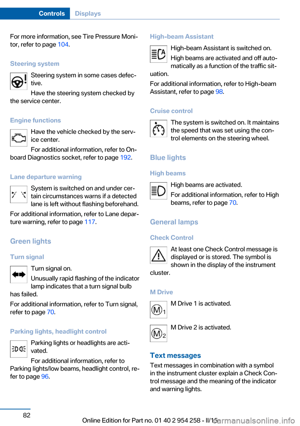
For more information, see Tire Pressure Moni‐
tor, refer to page 104.
Steering system Steering system in some cases defec‐
tive.
Have the steering system checked by
the service center.
Engine functions Have the vehicle checked by the serv‐ice center.
For additional information, refer to On-
board Diagnostics socket, refer to page 192.
Lane departure warning System is switched on and under cer‐
tain circumstances warns if a detected
lane is left without flashing beforehand.
For additional information, refer to Lane depar‐
ture warning, refer to page 117.
Green lights Turn signal Turn signal on.
Unusually rapid flashing of the indicator
lamp indicates that a turn signal bulb
has failed.
For additional information, refer to Turn signal,
refer to page 70.
Parking lights, headlight control Parking lights or headlights are acti‐
vated.
For additional information, refer to
Parking lights/low beams, headlight control, re‐
fer to page 96.High-beam Assistant
High-beam Assistant is switched on.
High beams are activated and off auto‐
matically as a function of the traffic sit‐
uation.
For additional information, refer to High-beam
Assistant, refer to page 98.
Cruise control The system is switched on. It maintains
the speed that was set using the con‐
trol elements on the steering wheel.
Blue lights
High beams High beams are activated.
For additional information, refer to High
beams, refer to page 70.
General lamps
Check Control At least one Check Control message is
displayed or is stored. The symbol is
shown in the display of the instrument
cluster.
M Drive M Drive 1 is activated.
M Drive 2 is activated.
Text messages Text messages in combination with a symbol
in the instrument cluster explain a Check Con‐
trol message and the meaning of the indicator
and warning lights.Seite 82ControlsDisplays82
Online Edition for Part no. 01 40 2 954 258 - II/15
Page 91 of 226
Display
Data regarding the service status or legally
mandated vehicle inspections are automati‐
cally transmitted to your service center before
a service due date.
Detailed information on service
requirements
More information on the scope of service re‐
quired can be displayed on the Control Dis‐
play.
On the Control Display:1."Vehicle info"2."Vehicle status"3. "Service required"
Required maintenance procedures and le‐
gally mandated inspections are displayed.4.Select an entry to call up detailed informa‐
tion.
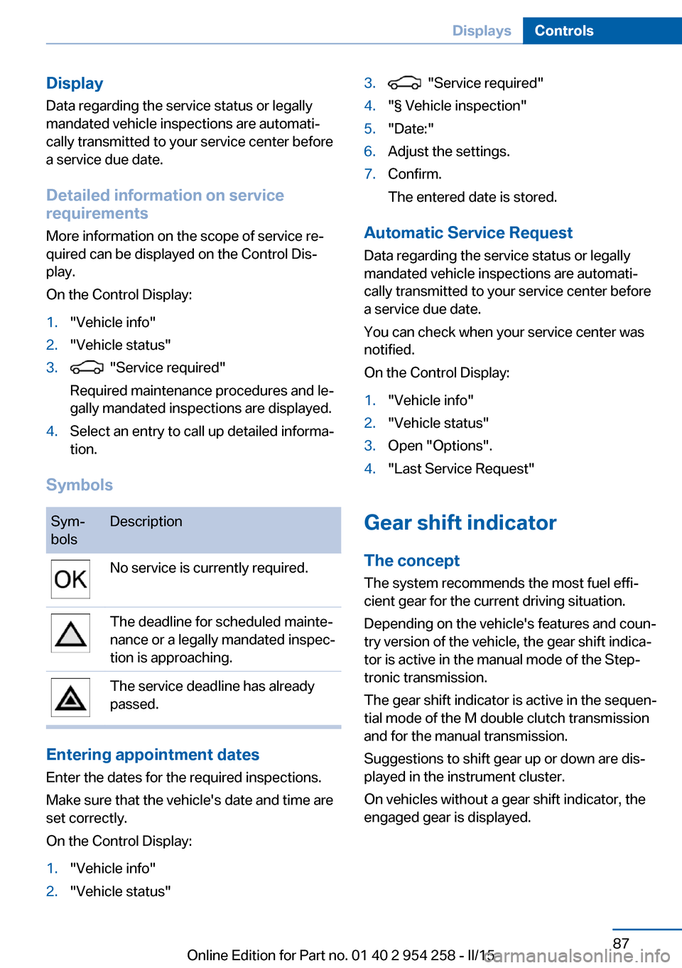
Symbols
Sym‐
bolsDescriptionNo service is currently required.The deadline for scheduled mainte‐
nance or a legally mandated inspec‐
tion is approaching.The service deadline has already
passed.
Entering appointment dates
Enter the dates for the required inspections.
Make sure that the vehicle's date and time are
set correctly.
On the Control Display:
1."Vehicle info"2."Vehicle status"3. "Service required"4."§ Vehicle inspection"5."Date:"6.Adjust the settings.7.Confirm.
The entered date is stored.
Automatic Service Request
Data regarding the service status or legally
mandated vehicle inspections are automati‐
cally transmitted to your service center before
a service due date.
You can check when your service center was
notified.
On the Control Display:
1."Vehicle info"2."Vehicle status"3.Open "Options".4."Last Service Request"
Gear shift indicator
The conceptThe system recommends the most fuel effi‐
cient gear for the current driving situation.
Depending on the vehicle's features and coun‐
try version of the vehicle, the gear shift indica‐
tor is active in the manual mode of the Step‐
tronic transmission.
The gear shift indicator is active in the sequen‐
tial mode of the M double clutch transmission
and for the manual transmission.
Suggestions to shift gear up or down are dis‐
played in the instrument cluster.
On vehicles without a gear shift indicator, the
engaged gear is displayed.
Seite 87DisplaysControls87
Online Edition for Part no. 01 40 2 954 258 - II/15
Page 99 of 226
3."Rotation"4.Turn the controller.
Settings are stored for the profile currently in
use.
Special windshield
The windshield is part of the system.
The shape of the windshield makes it possible
to display a precise image.
A film in the windshield prevents double im‐
ages from being displayed.
Therefore, have the special windshield re‐
placed by a service center only.
Shift point indicator General information
The display is in the Head-up Display.
Shift point indicator in the Head-up
Display
Switching on Shift lights are only shown in the Head-up Dis‐
play in the M view, refer to page 94.
1.Switch on Head-up Display, refer to
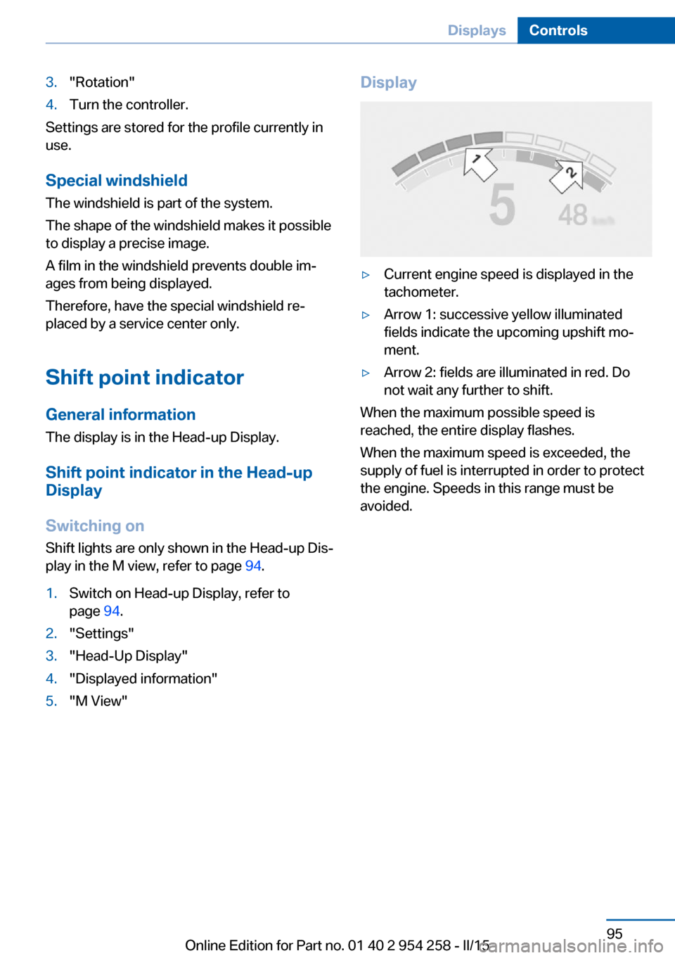
page 94.2."Settings"3."Head-Up Display"4."Displayed information"5."M View"Display▷Current engine speed is displayed in the
tachometer.▷Arrow 1: successive yellow illuminated
fields indicate the upcoming upshift mo‐
ment.▷Arrow 2: fields are illuminated in red. Do
not wait any further to shift.
When the maximum possible speed is
reached, the entire display flashes.
When the maximum speed is exceeded, the
supply of fuel is interrupted in order to protect
the engine. Speeds in this range must be
avoided.
Seite 95DisplaysControls95
Online Edition for Part no. 01 40 2 954 258 - II/15
Page 110 of 226
▷Inflation was not carried out according to
specifications.▷The tire inflation pressure has fallen below
the level of the last confirmation.
In this case:
▷Check the tire pressure and correct as
needed.▷Carry out a reset of the system after a tire
change.
System limits
The system does not function properly if a re‐
set has not been carried out, e.g., a flat tire is
reported though tire inflation pressures are
correct.
The tire inflation pressure depends on the
tire's temperature. Driving or exposure to the
sun will increase the tire's temperature, thus
increasing the tire inflation pressure. The tire
inflation pressure is reduced when the tire
temperature falls again. These circumstances
may cause a warning when temperatures fall
very sharply.
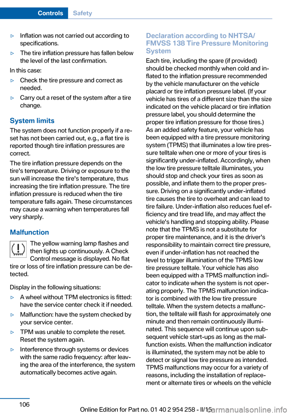
Malfunction The yellow warning lamp flashes and
then lights up continuously. A Check
Control message is displayed. No flat
tire or loss of tire inflation pressure can be de‐
tected.
Display in the following situations:
▷A wheel without TPM electronics is fitted:
have the service center check it if needed.▷Malfunction: have the system checked by
your service center.▷TPM was unable to complete the reset.
Reset the system again.▷Interference through systems or devices
with the same radio frequency: after leav‐
ing the area of the interference, the system
automatically becomes active again.Declaration according to NHTSA/
FMVSS 138 Tire Pressure Monitoring
System
Each tire, including the spare (if provided)
should be checked monthly when cold and in‐
flated to the inflation pressure recommended
by the vehicle manufacturer on the vehicle
placard or tire inflation pressure label. (If your
vehicle has tires of a different size than the size
indicated on the vehicle placard or tire inflation
pressure label, you should determine the
proper tire inflation pressure for those tires.)
As an added safety feature, your vehicle has
been equipped with a tire pressure monitoring
system (TPMS) that illuminates a low tire pres‐
sure telltale when one or more of your tires is
significantly under-inflated. Accordingly, when
the low tire pressure telltale illuminates, you
should stop and check your tires as soon as
possible, and inflate them to the proper pres‐
sure. Driving on a significantly under-inflated
tire causes the tire to overheat and can lead to
tire failure. Under-inflation also reduces fuel ef‐
ficiency and tire tread life, and may affect the
vehicle's handling and stopping ability. Please
note that the TPMS is not a substitute for
proper tire maintenance, and it is the driver's
responsibility to maintain correct tire pressure,
even if under-inflation has not reached the
level to trigger illumination of the TPMS low
tire pressure telltale. Your vehicle has also
been equipped with a TPMS malfunction indi‐
cator to indicate when the system is not oper‐
ating properly. The TPMS malfunction indica‐
tor is combined with the low tire pressure
telltale. When the system detects a malfunc‐
tion, the telltale will flash for approximately one
minute and then remain continuously illumi‐
nated. This sequence will continue upon sub‐
sequent vehicle start-ups as long as the mal‐
function exists. When the malfunction indicator
is illuminated, the system may not be able to
detect or signal low tire pressure as intended.
TPMS malfunctions may occur for a variety of
reasons, including the installation of replace‐
ment or alternate tires or wheels on the vehicleSeite 106ControlsSafety106
Online Edition for Part no. 01 40 2 954 258 - II/15
Page 198 of 226
the service center if you are unfamiliar those or
if they have not been described here.
You can obtain a selection of replacement
bulbs at the service center.
Danger of burns
Only change bulbs when they are cool;
otherwise, there is a danger of getting
burned.◀
Working on the lighting system
When working on the lighting system,
you should always reel off the lights affected to
prevent short circuits.
To avoid possible injury or equipment damage
when replacing bulbs, observe any instructions
provided by the bulb manufacturer.◀
Do not touch the bulbs
Do not touch the glass of new bulbs with
your bare hands, as even minute amounts of
contamination will burn into the bulb's surface
and reduce its service life.
Use a clean tissue, cloth or something similar,
or hold the bulb by its base.◀
Light-emitting diodes (LEDs)
Some items of equipment use light-emitting
diodes installed behind a cover as a light
source.
These light-emitting diodes, which are related
to conventional lasers, are officially designated as Class 1 light-emitting diodes.
Do not remove the covers
Do not remove the covers, and never
stare into the unfiltered light for several hours;
otherwise, irritation of the retina could result.◀
Headlight glass
Condensation can form on the inside of the ex‐
ternal lights in cool or humid weather. When
driving with the light switched on, the conden‐
sation evaporates after a short time. The head‐
light glass does not need to be changed.If the headlights do not dim despite driving
with the light switched on, increasing humidity
forms, e. g. water droplets in the light, have the
service center check this.
Headlight setting The headlight adjustments can be affected by
changing lights and bulbs. Have the head‐
lights' settings checked and corrected by serv‐
ice after a replacement.
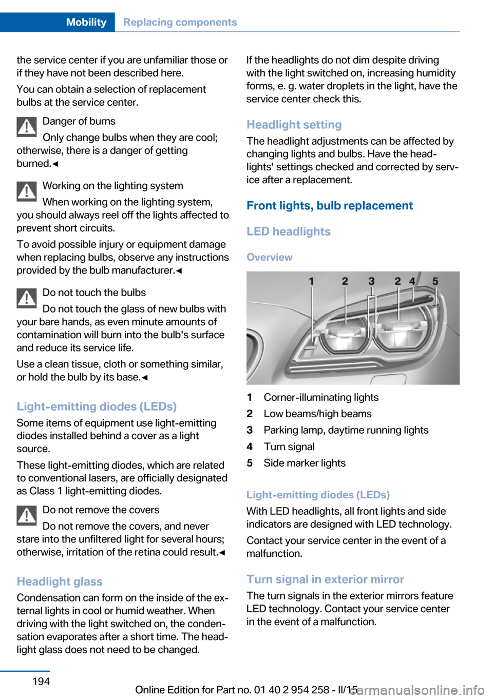
Front lights, bulb replacement LED headlights Overview1Corner-illuminating lights2Low beams/high beams3Parking lamp, daytime running lights4Turn signal5Side marker lights
Light-emitting diodes (LEDs)
With LED headlights, all front lights and side
indicators are designed with LED technology.
Contact your service center in the event of a
malfunction.
Turn signal in exterior mirrorThe turn signals in the exterior mirrors feature
LED technology. Contact your service center
in the event of a malfunction.
Seite 194MobilityReplacing components194
Online Edition for Part no. 01 40 2 954 258 - II/15
Page 220 of 226
IIce warning, see External temperature warning 84
Icy roads, see External tem‐ perature warning 84
Identification marks, tires 177
Identification number, see ve‐ hicle identification num‐
ber 9
iDrive 18
Ignition key, refer to Remote control 34
Ignition off 64
Ignition on 64
Indication of a flat tire 105 , 107
Indicator and alarm lamps, see Check Control 80
Indicator lamp, see Check Control 80
Individual air distribution 141
Individual settings, refer to M Drive 123
Individual settings, refer to Personal Profile 35
Inflation pressure, tires 176
Inflation pressure warning FTM, tires 107
Info display, refer to On- Board computer 89
Initialize, Tire Pressure Moni‐ tor TPM 105
Initializing, Flat Tire Monitor FTM 107
Instrument cluster 79
Instrument cluster, electronic displays 79
Instrument lighting 99
Integrated key 34
Integrated Owner's Manual in the vehicle 29
Intelligent Emergency Re‐ quest 198
Intelligent Safety 108 Intensity, AUTO pro‐
gram 141
Interior equipment 147
Interior lights 99
Interior lights during unlock‐ ing 37
Interior lights with the vehicle locked 38
Interior motion sensor 45
Interior rearview mirror, auto‐ matic dimming feature 58
Internet page 6
Interval display, service re‐ quirements 86
Interval mode 71
J
Jacking points for the vehicle jack 196
Jump-starting 199
K
Key/remote control 34
Keyless Go, refer to Comfort Access 41
Key Memory, refer to Per‐ sonal Profile 35
Knee airbag 102
L Lamp replacement, front 193
Lamp replacement, rear 195
Lane departure warning 117
Lane margin, warning 117
Language on Control Dis‐ play 93
Lashing eyes, securing cargo 167
LATCH child restraint sys‐ tem 62
Launch Control 76
Leather, care 206 LED headlights, bulb replace‐
ment 194
LED light 194
LEDs, light-emitting di‐ odes 194
Length, vehicle 210
Letters and numbers, enter‐ ing 24
License plate lamp, bulb re‐ placement 195
Light alloy wheels, care 206
Light control 97
Light-emitting diodes, LEDs 194
Lighting 96
Lighting, speaker 100
Lights 96
Lights and bulbs 193
Light switch 96
Load 167
Loading 166
Lock, door 39
Locking/unlocking via door lock 39
Locking/unlocking with re‐ mote control 37
Locking, automatic 44
Locking, settings 43
Locking via trunk lid 41
Lock, power window 46
Locks, doors, and win‐ dows 63
Low beams 96
Low beams, automatic, refer to High-beam Assistant 98
Lower back support 51
Low Speed Assistant 74
Lumbar support 51
M
Maintenance 191
Maintenance require‐ ments 191
Maintenance, service require‐ ments 86 Seite 216ReferenceEverything from A to Z216
Online Edition for Part no. 01 40 2 954 258 - II/15
Page 223 of 226
Seats 50
Seat ventilation, front 53
Selection list in instrument cluster 89
Selector lever 73
Selector lever position 73
Sensors, care 207
Sequential mode 74
Service and warranty 8
Service requirements, Condi‐ tion Based Service
CBS 191
Service requirements, dis‐ play 86
Services, ConnectedDrive
Servotronic 127
SET button, see Cruise con‐ trol 129
Settings, locking/unlock‐ ing 43
Settings, M Drive 123
Settings on Control Dis‐ play 92
Settings, storing for seat, mir‐ rors, steering wheel 56
Shift point indicator 95
Shoulder support 52
Side airbags 101
Side View 136
Signaling, horn 14
Signals when unlocking 43
Sitting safely 50
Size 210
Ski bag 152
Smallest turning radius 210
Smoker's package 149
Snow chains 184
Socket 150
Socket, OBD Onboard Diag‐ nostics 192
SOS button 198
Spare fuse 197
Speaker lighting 100
Specified engine oil types 189
Speed, average 90 Speed limit detection, on-
board computer 91
Speed limiter, display 88
Speed Limit Information 88
Speed warning 91
Split screen 23
Sport displays, torque dis‐ play, performance dis‐
play 91
Stability control systems 123
Standard view, head-up dis‐ play 94
Start/stop, automatic func‐ tion 66
Start/Stop button 64
Start function during malfunc‐ tion 35
Starting the engine 65
Status control display, tires 105
Status information, iDrive 22
Status of Owner's Manual 7
Steering assistance 127
Steering wheel, adjusting 58
Steering wheel heating 59
Steering wheel memory 56
Stopping the engine 65
Storage compartments 154
Storage compartments, loca‐ tions 154
Storage, tires 181
Storing the vehicle 207
Suitable engine oils 189
Summer tires, tread 179
Sun visor 149
Supplementary text mes‐ sage 83
Surround View 133
Switch-on times, parked-car ventilation 146
Switch, refer to Cockpit 14
Symbols 6
Symbols in the status field 22
SYNC program, automatic cli‐ mate control 142 System states of dynamic
driving 86
T
Tachometer 83
Tail and brake lights 195
Tail lights 195
Tail lights, bulb replace‐ ment 195
Technical changes, refer to Safety 7
Technical data 210
Technology, BMW M 160
Telephone, see user's manual for Navigation, Entertain‐
ment and Communication
Temperature, automatic cli‐ mate control 141
Temperature display for ex‐ ternal temperature 84
Temperature, engine oil 83
Terminal, starting aid 200
Text message, supplemen‐ tary 83
Theft alarm system, refer to Alarm system 44
Thermal camera, see Night Vision 114
Thigh support 51
Through-loading system 151
Tilt alarm sensor 45
Tilt glass roof 48
Tilt, seats 50
Time of arrival 91
Tire damage 179
Tire identification marks 177
Tire inflation pressure 176
Tire inflation pressure moni‐ tor, refer to FTM 107
Tire Pressure Monitor TPM 104
Tires, changing 180
Tire sealant 181
Tires, everything on wheels and tires 176 Seite 219Everything from A to ZReference219
Online Edition for Part no. 01 40 2 954 258 - II/15