ignition BMW MOTORRAD K 1200 GT 2006 Rider's Manual (in English)
[x] Cancel search | Manufacturer: BMW MOTORRAD, Model Year: 2006, Model line: K 1200 GT, Model: BMW MOTORRAD K 1200 GT 2006Pages: 172, PDF Size: 1.98 MB
Page 127 of 172
/rear-light bulb) clockwise to
install it in the bulb housing.
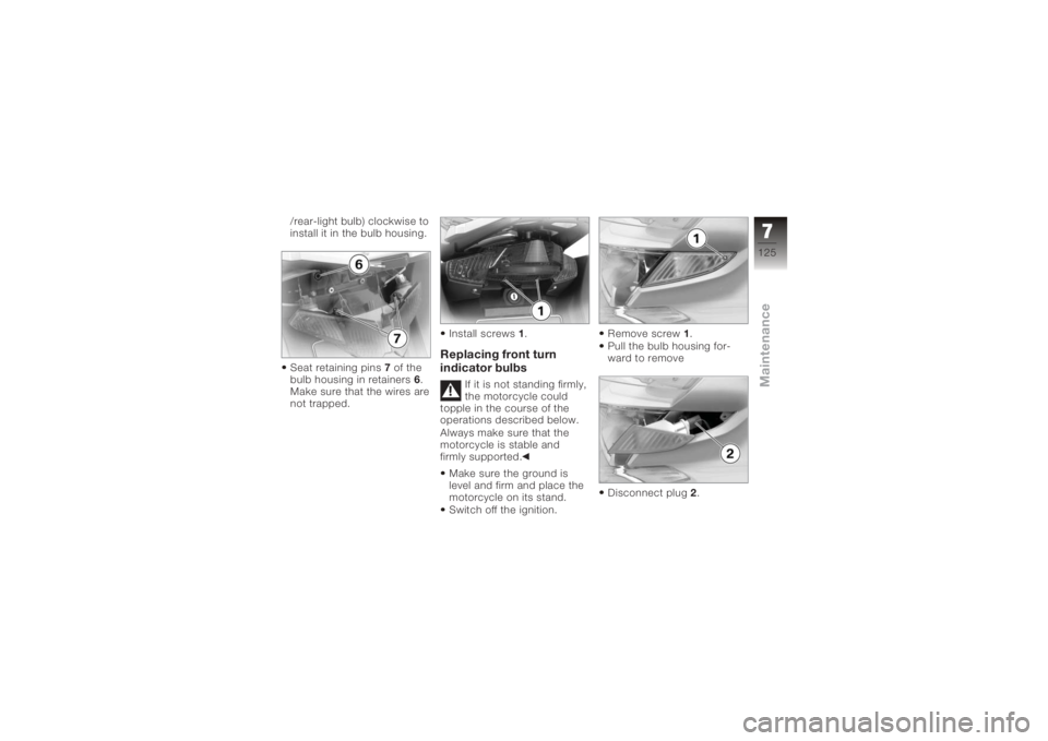
Seat retaining pins7of the
bulb housing in retainers 6.
Make sure that the wires are
not trapped. Install screws
1.
Replacing front turn
indicator bulbs
If it is not standing firmly,
the motorcycle could
topple in the course of the
operations described below.
Always make sure that the
motorcycle is stable and
firmly supported.
Make sure the ground is
level and firm and place the
motorcycle on its stand.
Switch off the ignition. Remove screw
1.
Pull the bulb housing for-
ward to remove
Disconnect plug 2.
7125zMaintenance
Page 129 of 172
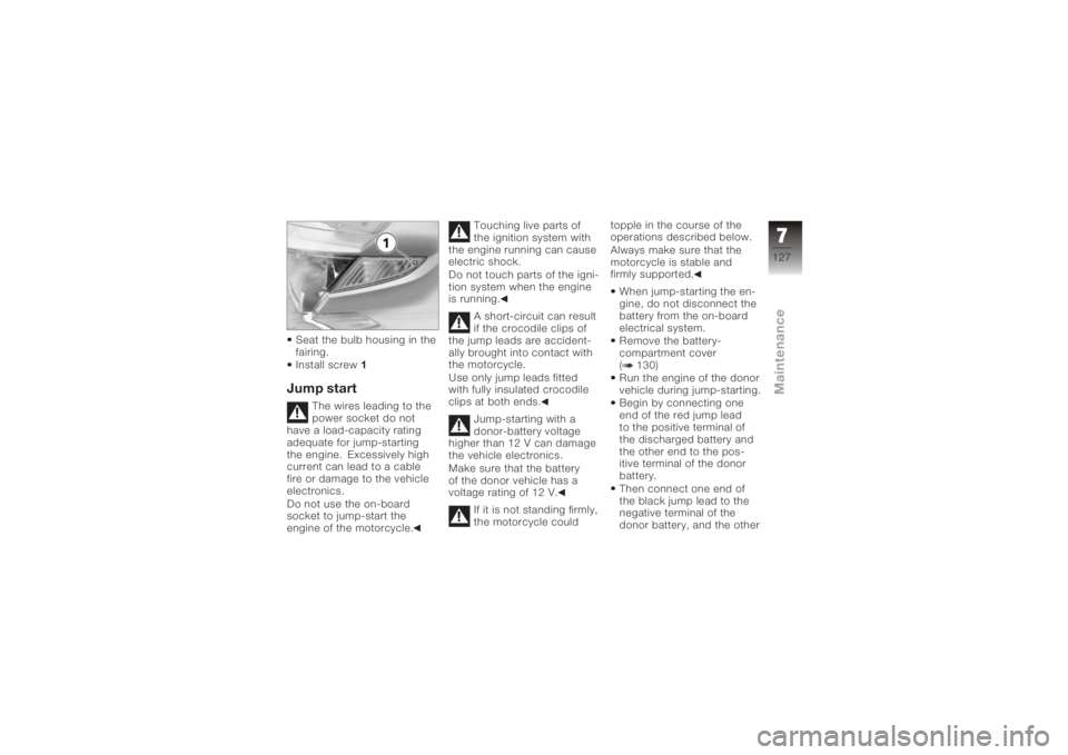
Seat the bulb housing in the
fairing.
Install screw1Jump start
The wires leading to the
power socket do not
have a load-capacity rating
adequate for jump-starting
the engine. Excessively high
current can lead to a cable
fire or damage to the vehicle
electronics.
Do not use the on-board
socket to jump-start the
engine of the motorcycle. Touching live parts of
the ignition system with
the engine running can cause
electric shock.
Do not touch parts of the igni-
tion system when the engine
is running.
A short-circuit can result
if the crocodile clips of
the jump leads are accident-
ally brought into contact with
the motorcycle.
Use only jump leads fitted
with fully insulated crocodile
clips at both ends.
Jump-starting with a
donor-battery voltage
higher than 12 V can damage
the vehicle electronics.
Make sure that the battery
of the donor vehicle has a
voltage rating of 12 V.
If it is not standing firmly,
the motorcycle could topple in the course of the
operations described below.
Always make sure that the
motorcycle is stable and
firmly supported.
When jump-starting the en-
gine, do not disconnect the
battery from the on-board
electrical system.
Remove the battery-
compartment cover
( 130)
Run the engine of the donor
vehicle during jump-starting.
Begin by connecting one
end of the red jump lead
to the positive terminal of
the discharged battery and
the other end to the pos-
itive terminal of the donor
battery.
Then connect one end of
the black jump lead to the
negative terminal of the
donor battery, and the other
7127zMaintenance
Page 133 of 172
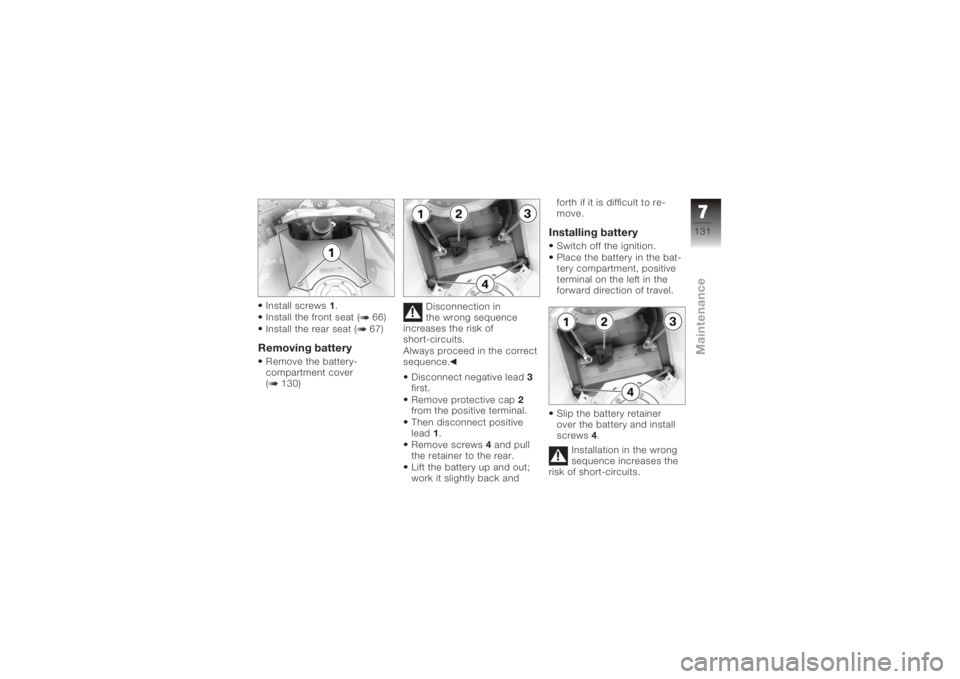
Install screws1.
Install the front seat ( 66)
Install the rear seat ( 67)Removing batteryRemove the battery-
compartment cover
( 130) Disconnection in
the wrong sequence
increases the risk of
short-circuits.
Always proceed in the correct
sequence.
Disconnect negative lead 3
first.
Remove protective cap 2
from the positive terminal.
Then disconnect positive
lead 1.
Remove screws 4and pull
the retainer to the rear.
Lift the battery up and out;
work it slightly back and forth if it is difficult to re-
move.
Installing batterySwitch off the ignition.
Place the battery in the bat-
tery compartment, positive
terminal on the left in the
forward direction of travel.
Slip the battery retainer
over the battery and install
screws
4.
Installation in the wrong
sequence increases the
risk of short-circuits.
7131zMaintenance
Page 134 of 172
Always proceed in the correct
sequence.
Never install the battery
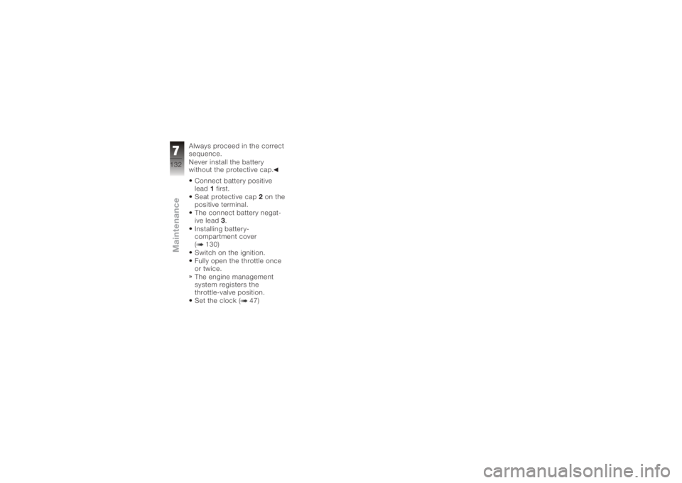
without the protective cap.Connect battery positive
lead 1first.
Seat protective cap 2on the
positive terminal.
The connect battery negat-
ive lead 3.
Installing battery-
compartment cover
( 130)
Switch on the ignition.
Fully open the throttle once
or twice.
The engine management
system registers the
throttle-valve position.
Set the clock ( 47)
7132zMaintenance
Page 142 of 172
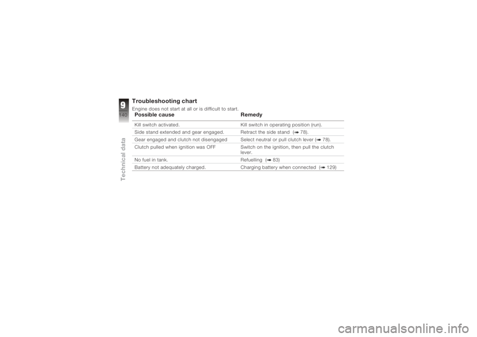
Troubleshooting chartEngine does not start at all or is difficult to start.Possible causeRemedyKill switch activated. Kill switch in operating position (run).
Side stand extended and gear engaged. Retract the side stand ( 78).
Gear engaged and clutch not disengaged Select neutral or pull clutch lever ( 78).
Clutch pulled when ignition was OFF Switch on the ignition, then pull the clutch
lever.
No fuel in tank. Refuelling ( 83)
Battery not adequately charged. Charging battery when connected ( 129)
9140zTechnical data
Page 168 of 172
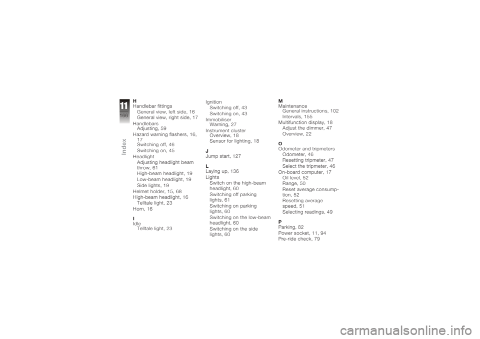
H
Handlebar fittingsGeneral view, left side, 16
General view, right side, 17
Handlebars Adjusting, 59
Hazard warning flashers, 16, 17
Switching off, 46
Switching on, 45
Headlight Adjusting headlight beam
throw, 61
High-beam headlight, 19
Low-beam headlight, 19
Side lights, 19
Helmet holder, 15, 68
High-beam headlight, 16 Telltale light, 23
Horn, 16
I
Idle Telltale light, 23 Ignition
Switching off, 43
Switching on, 43
Immobiliser Warning, 27
Instrument cluster Overview, 18
Sensor for lighting, 18
J
Jump start, 127
L
Laying up, 136
Lights Switch on the high-beam
headlight, 60
Switching off parking
lights, 61
Switching on parking
lights, 60
Switching on the low-beam
headlight, 60
Switching on the side
lights, 60 M
Maintenance
General instructions, 102
Intervals, 155
Multifunction display, 18 Adjust the dimmer, 47
Overview, 22
O
Odometer and tripmeters Odometer, 46
Resetting tripmeter, 47
Select the tripmeter, 46
On-board computer, 17 Oil level, 52
Range, 50
Reset average consump-
tion, 52
Resetting average
speed, 51
Selecting readings, 49
P
Parking, 82
Power socket, 11, 94
Pre-ride check, 79
11166zIndex