engine BMW X1 2013 E84 Owner's Guide
[x] Cancel search | Manufacturer: BMW, Model Year: 2013, Model line: X1, Model: BMW X1 2013 E84Pages: 299, PDF Size: 6.66 MB
Page 73 of 299
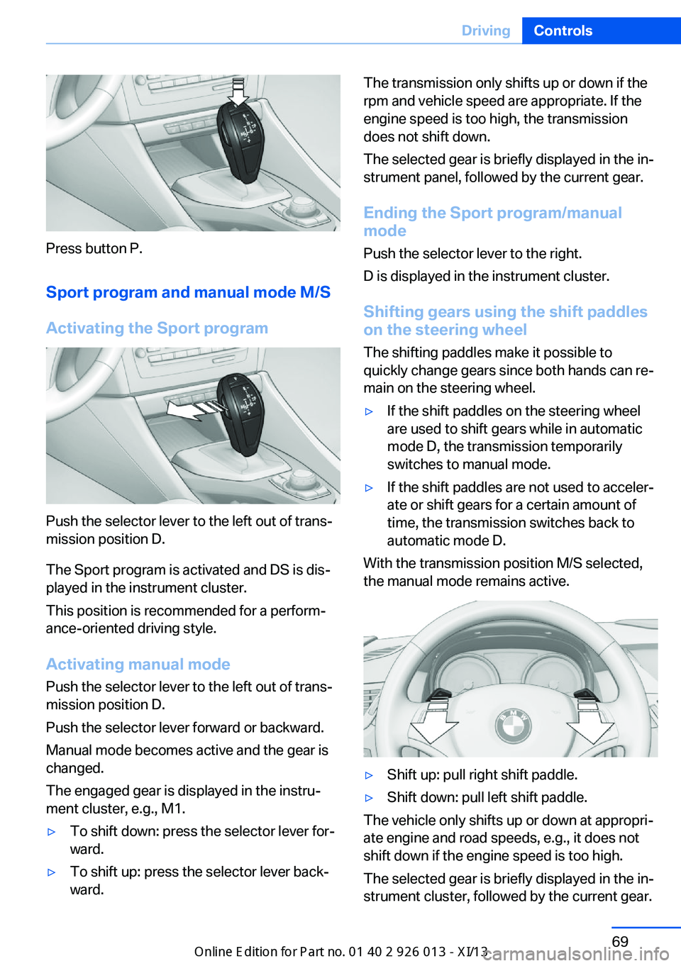
Press button P.Sport program and manual mode M/S
Activating the Sport program
Push the selector lever to the left out of trans‐
mission position D.
The Sport program is activated and DS is dis‐
played in the instrument cluster.
This position is recommended for a perform‐
ance-oriented driving style.
Activating manual mode
Push the selector lever to the left out of trans‐
mission position D.
Push the selector lever forward or backward.
Manual mode becomes active and the gear is
changed.
The engaged gear is displayed in the instru‐
ment cluster, e.g., M1.
▷To shift down: press the selector lever for‐
ward.▷To shift up: press the selector lever back‐
ward.The transmission only shifts up or down if the
rpm and vehicle speed are appropriate. If the
engine speed is too high, the transmission
does not shift down.
The selected gear is briefly displayed in the in‐
strument panel, followed by the current gear.
Ending the Sport program/manual
mode
Push the selector lever to the right.
D is displayed in the instrument cluster.
Shifting gears using the shift paddles
on the steering wheel
The shifting paddles make it possible to
quickly change gears since both hands can re‐
main on the steering wheel.▷If the shift paddles on the steering wheel
are used to shift gears while in automatic
mode D, the transmission temporarily
switches to manual mode.▷If the shift paddles are not used to acceler‐
ate or shift gears for a certain amount of
time, the transmission switches back to
automatic mode D.
With the transmission position M/S selected,
the manual mode remains active.
▷Shift up: pull right shift paddle.▷Shift down: pull left shift paddle.
The vehicle only shifts up or down at appropri‐
ate engine and road speeds, e.g., it does not
shift down if the engine speed is too high.
The selected gear is briefly displayed in the in‐
strument cluster, followed by the current gear.
Seite 69DrivingControls69
Online Edition for Part no. 01 40 2 911 269 - VI/13
Page 76 of 299
Tachometer
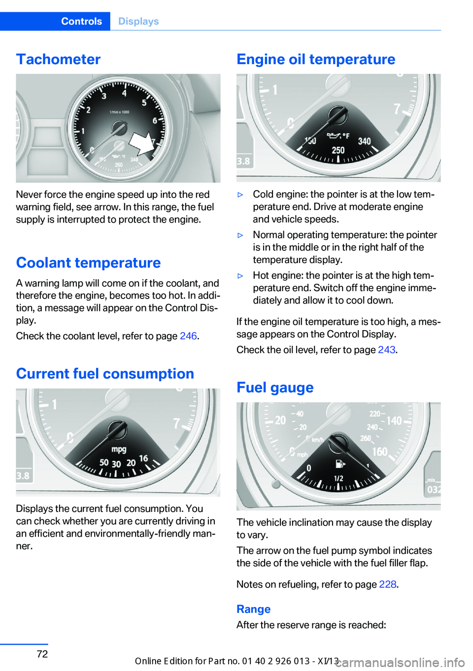
Never force the engine speed up into the red
warning field, see arrow. In this range, the fuel
supply is interrupted to protect the engine.
Coolant temperature A warning lamp will come on if the coolant, and
therefore the engine, becomes too hot. In addi‐
tion, a message will appear on the Control Dis‐
play.
Check the coolant level, refer to page 246.
Current fuel consumption
Displays the current fuel consumption. You
can check whether you are currently driving in
an efficient and environmentally-friendly man‐
ner.
Engine oil temperature▷Cold engine: the pointer is at the low tem‐
perature end. Drive at moderate engine
and vehicle speeds.▷Normal operating temperature: the pointer
is in the middle or in the right half of the
temperature display.▷Hot engine: the pointer is at the high tem‐
perature end. Switch off the engine imme‐
diately and allow it to cool down.
If the engine oil temperature is too high, a mes‐
sage appears on the Control Display.
Check the oil level, refer to page 243.
Fuel gauge
The vehicle inclination may cause the display
to vary.
The arrow on the fuel pump symbol indicates
the side of the vehicle with the fuel filler flap.
Notes on refueling, refer to page 228.
Range
After the reserve range is reached:
Seite 72ControlsDisplays72
Online Edition for Part no. 01 40 2 911 269 - VI/13
Page 77 of 299
▷A message is briefly displayed on the Con‐
trol Display.▷The remaining range is shown on the com‐
puter.▷When a dynamic driving style is used, such
as when corners are taken rapidly, engine
functions are not ensured.
The message appears continuously below a
range of approx. 30 miles/50 km.
Refuel promptly
At the latest, refuel at a range below
30 miles/50 km; otherwise, the engine function
is not ensured and damage may occur.◀
Computer Displaying information on the
instrument panel
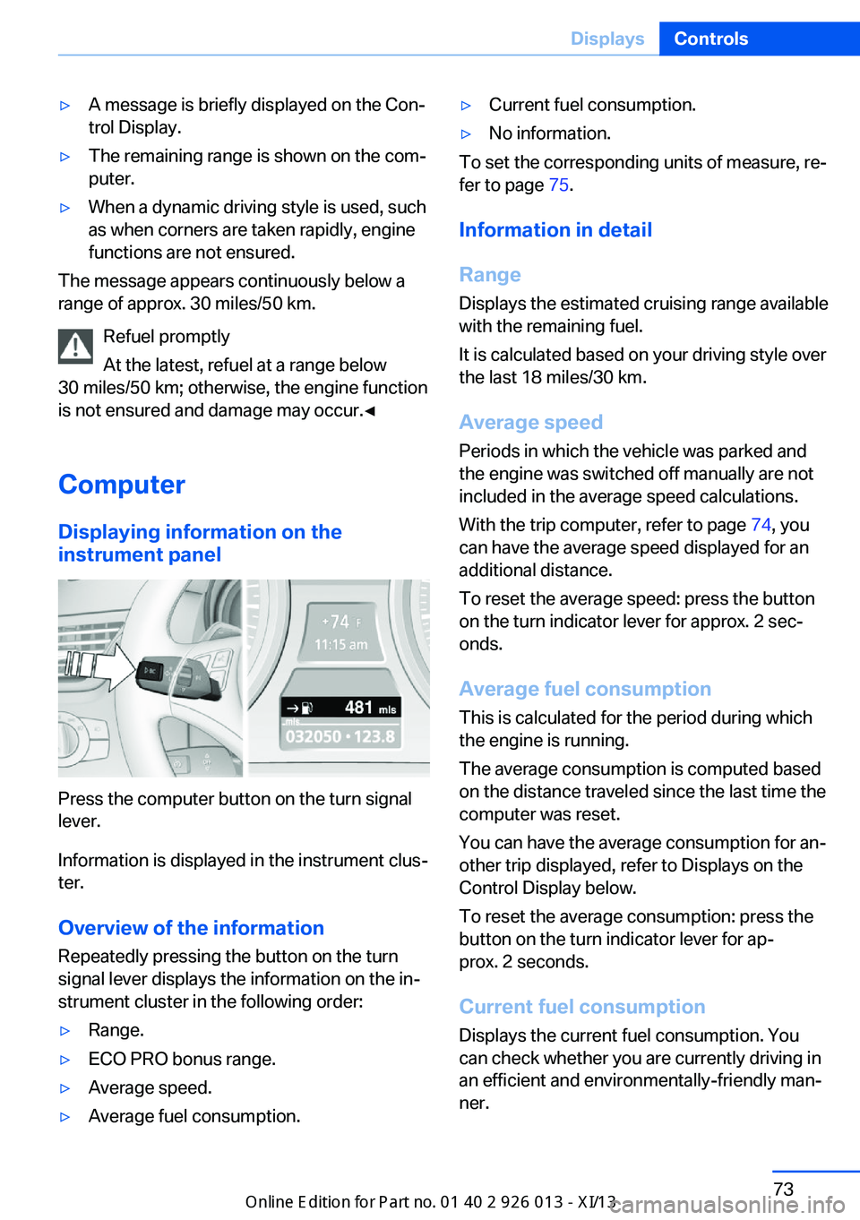
Press the computer button on the turn signal
lever.
Information is displayed in the instrument clus‐
ter.
Overview of the information Repeatedly pressing the button on the turn
signal lever displays the information on the in‐
strument cluster in the following order:
▷Range.▷ECO PRO bonus range.▷Average speed.▷Average fuel consumption.▷Current fuel consumption.▷No information.
To set the corresponding units of measure, re‐
fer to page 75.
Information in detail
Range
Displays the estimated cruising range available
with the remaining fuel.
It is calculated based on your driving style over
the last 18 miles/30 km.
Average speed
Periods in which the vehicle was parked and
the engine was switched off manually are not
included in the average speed calculations.
With the trip computer, refer to page 74, you
can have the average speed displayed for an
additional distance.
To reset the average speed: press the button
on the turn indicator lever for approx. 2 sec‐
onds.
Average fuel consumption
This is calculated for the period during which
the engine is running.
The average consumption is computed based
on the distance traveled since the last time the
computer was reset.
You can have the average consumption for an‐
other trip displayed, refer to Displays on the
Control Display below.
To reset the average consumption: press the
button on the turn indicator lever for ap‐
prox. 2 seconds.
Current fuel consumption Displays the current fuel consumption. You
can check whether you are currently driving in
an efficient and environmentally-friendly man‐
ner.
Seite 73DisplaysControls73
Online Edition for Part no. 01 40 2 911 269 - VI/13
Page 79 of 299
▷Confirming the selected display or set
values.▷Calling up computer information 73.SymbolFunctionWith the lights switched on:
Dimming instrument lighting,
refer to page 87Calling up Check Control, refer
to page 80Checking the engine oil level,
refer to page 243Setting the time, refer to
page 75Setting date, refer to
page 76Viewing service requirement
display, refer to page 78
Exiting displays
The external temperature reading and the time
reappear when you press button 2 or if you
make no entries within approx. 15 seconds. If
required, complete the current setting first.
Units of measure
The units for fuel consumption, route/distance,
temperature, and pressure can be changed.1."Settings"2."Language/Units"3.Select the desired menu item.4.Select the desired unit.
The settings are stored for the remote control
currently in use.
Clock
Setting the time
In the instrument cluster To set the 12h/24h format, refer to Setting the
time format below.
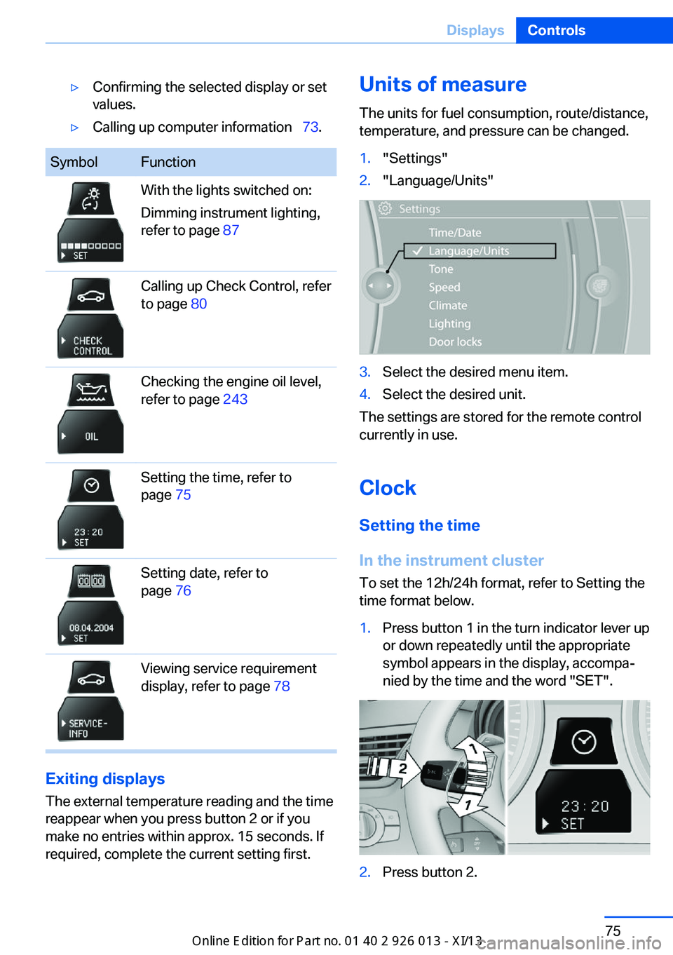
1.Press button 1 in the turn indicator lever up
or down repeatedly until the appropriate
symbol appears in the display, accompa‐
nied by the time and the word "SET".2.Press button 2.Seite 75DisplaysControls75
Online Edition for Part no. 01 40 2 911 269 - VI/13
Page 82 of 299
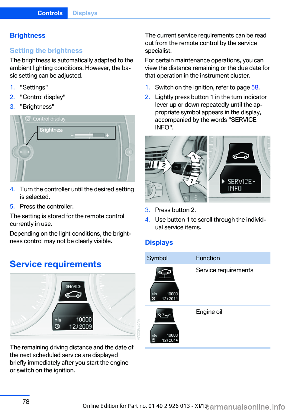
Brightness
Setting the brightness
The brightness is automatically adapted to the
ambient lighting conditions. However, the ba‐
sic setting can be adjusted.1."Settings"2."Control display"3."Brightness"4.Turn the controller until the desired setting
is selected.5.Press the controller.
The setting is stored for the remote control
currently in use.
Depending on the light conditions, the bright‐
ness control may not be clearly visible.
Service requirements
The remaining driving distance and the date of
the next scheduled service are displayed
briefly immediately after you start the engine
or switch on the ignition.
The current service requirements can be read
out from the remote control by the service
specialist.
For certain maintenance operations, you can
view the distance remaining or the due date for
that operation in the instrument cluster.1.Switch on the ignition, refer to page 58.2.Lightly press button 1 in the turn indicator
lever up or down repeatedly until the ap‐
propriate symbol appears in the display,
accompanied by the words "SERVICE
INFO".3.Press button 2.4.Use button 1 to scroll through the individ‐
ual service items.
Displays
SymbolFunctionService requirementsEngine oilSeite 78ControlsDisplays78
Online Edition for Part no. 01 40 2 911 269 - VI/13
Page 84 of 299
7.Create the settings.8.Press the controller to apply the setting.
The year is highlighted.9.Turn the controller to make the adjust‐
ment.10.Press the controller to apply the setting.
The date entry is stored.
To exit from the menu:
Move the controller to the left.
Automatic Service Request
Data regarding the maintenance status or le‐
gally mandated inspections of the vehicle are
automatically transmitted to your service cen‐
ter before a service due date.
You can check when your service center was
notified.
1."Vehicle Info"2."Vehicle status"3.Open "Options".4."Last Service Request"
Check Control
The concept The Check Control monitors vehicle functions
and alerts you to any malfunctions in the sys‐
tems monitored.
A Check Control message consists of indicator and warning lamps in the instrument cluster
and, in some circumstances, an acoustic signal
and text messages at the top of the Control
Display.
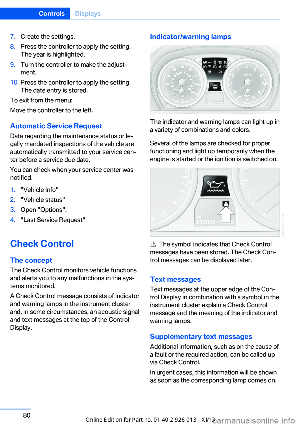
Indicator/warning lamps
The indicator and warning lamps can light up in
a variety of combinations and colors.
Several of the lamps are checked for proper
functioning and light up temporarily when the
engine is started or the ignition is switched on.
The symbol indicates that Check Control
messages have been stored. The Check Con‐
trol messages can be displayed later.
Text messages Text messages at the upper edge of the Con‐
trol Display in combination with a symbol in the
instrument cluster explain a Check Control
message and the meaning of the indicator and
warning lamps.
Supplementary text messages
Additional information, such as on the cause of
a fault or the required action, can be called up
via Check Control.
In urgent cases, this information will be shown
as soon as the corresponding lamp comes on.
Seite 80ControlsDisplays80
Online Edition for Part no. 01 40 2 911 269 - VI/13
Page 87 of 299
LampsVehicle equipment
This chapter describes all series equipment as
well as country-specific and special equipment
offered for this model series.Therefore, it also
describes equipment that may not be found in
your vehicle, for instance due to the selected
special equipment or the country version. This
also applies to safety-related functions and
systems.
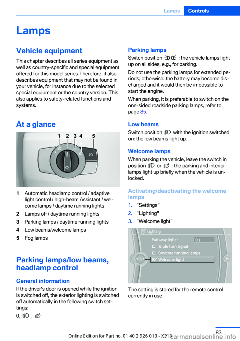
At a glance1Automatic headlamp control / adaptive
light control / high-beam Assistant / wel‐
come lamps / daytime running lights2Lamps off / daytime running lights3Parking lamps / daytime running lights4Low beams/welcome lamps5Fog lamps
Parking lamps/low beams,
headlamp control
General information If the driver's door is opened while the ignition
is switched off, the exterior lighting is switched
off automatically in the following switch set‐
tings:
0,
,
Parking lamps
Switch position
: the vehicle lamps light
up on all sides, e.g., for parking.
Do not use the parking lamps for extended pe‐
riods; otherwise, the battery may become dis‐
charged and it would then be impossible to
start the engine.
When parking, it is preferable to switch on the
one-sided roadside parking lamps, refer to
page 85.
Low beams Switch position
with the ignition switched
on: the low beams light up.
Welcome lamps When parking the vehicle, leave the switch in
position
or : the parking and interior
lamps light up briefly when the vehicle is un‐
locked.
Activating/deactivating the welcome
lamps
1."Settings"2."Lighting"3."Welcome light"
The setting is stored for the remote control
currently in use.
Seite 83LampsControls83
Online Edition for Part no. 01 40 2 911 269 - VI/13
Page 96 of 299
Do not initialize the system when driving with
snow chains.1."Vehicle Info"2."Vehicle status"3. "Reset"4.Start the engine - do not drive away.5.Start the initialization with "Reset".6.Drive away.
The initialization is completed while driving,
which can be interrupted at any time.
The initialization automatically continues when
driving resumes.
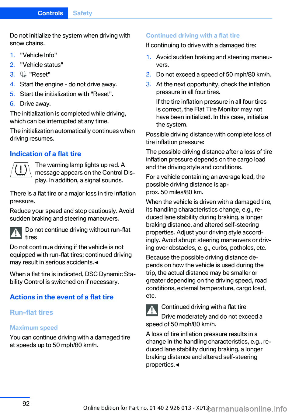
Indication of a flat tire The warning lamp lights up red. A
message appears on the Control Dis‐
play. In addition, a signal sounds.
There is a flat tire or a major loss in tire inflation
pressure.
Reduce your speed and stop cautiously. Avoid
sudden braking and steering maneuvers.
Do not continue driving without run-flat
tires
Do not continue driving if the vehicle is not
equipped with run-flat tires; continued driving
may result in serious accidents.◀
When a flat tire is indicated, DSC Dynamic Sta‐
bility Control is switched on if necessary.
Actions in the event of a flat tire
Run-flat tires Maximum speed
You can continue driving with a damaged tire
at speeds up to 50 mph/80 km/h.
Continued driving with a flat tire
If continuing to drive with a damaged tire:1.Avoid sudden braking and steering maneu‐
vers.2.Do not exceed a speed of 50 mph/80 km/h.3.At the next opportunity, check the inflation
pressure in all four tires.
If the tire inflation pressure in all four tires
is correct, the Flat Tire Monitor may not
have been initialized. In this case, initialize
the system.
Possible driving distance with complete loss of
tire inflation pressure:
The possible driving distance after a loss of tire
inflation pressure depends on the cargo load
and the driving style and conditions.
For a vehicle containing an average load, the
possible driving distance is ap‐
prox. 50 miles/80 km.
When the vehicle is driven with a damaged tire,
its handling characteristics change, e.g., re‐
duced lane stability during braking, a longer
braking distance, and altered self-steering
properties. Adjust your driving style accord‐
ingly. Avoid abrupt steering maneuvers or driv‐
ing over obstacles, e. g., curbs, potholes, etc.
Because the possible driving distance de‐
pends on how the vehicle is used during the
trip, the actual distance may be smaller or
greater depending on the driving speed, road
conditions, external temperature, cargo load,
etc.
Continued driving with a flat tire
Drive moderately and do not exceed a
speed of 50 mph/80 km/h.
A loss of tire inflation pressure results in a
change in the handling characteristics, e.g., re‐
duced lane stability during braking, a longer
braking distance and altered self-steering
properties.◀
Seite 92ControlsSafety92
Online Edition for Part no. 01 40 2 911 269 - VI/13
Page 98 of 299
Resetting the systemReset the system after each correction of the
tire inflation pressure and after every tire or
wheel change.1."Vehicle Info"2."Vehicle status"3. "Reset"4.Start the engine - do not drive away.5.Reset the tire pressure using "Reset".6.Drive away.
The tires are shown in gray and "Resetting
TPM..." is displayed.
After driving for a few minutes, the set tire in‐
flation pressures are applied as set values. The
resetting process is completed automatically
as you drive. The tires are shown in green and
"TPM active" is shown on the Control Display.
The trip can be interrupted at any time. If you
drive away again, the process resumes auto‐
matically.
If a flat tire is detected while the system is re‐
setting, all tires on the Control Display are dis‐
played in yellow. The message "Low tire!" is
shown.
Low tire pressure message The small warning lamp lights up yel‐
low and the large warning lamp lights
up red. A message appears on the
Control Display. In addition, a signal
sounds.
▷There is a flat tire or a major loss in tire in‐
flation pressure.▷The system was not reset after a wheel
change and thus issues warnings based on
the inflation pressures initialized last.
Reduce your speed and stop cautiously. Avoid
sudden braking and steering maneuvers.
Do not continue driving without run-flat
tires
Do not continue driving if the vehicle is not
equipped with run-flat tires; continued driving
may result in serious accidents.◀
When a low inflation pressure is indicated,
DSC Dynamic Stability Control is switched on
if necessary.
Actions in the event of a flat tire
Run-flat tires Maximum speed
You can continue driving with a damaged tire
at speeds up to 50 mph/80 km/h.
Continued driving with a flat tire
If continuing to drive with a damaged tire:1.Avoid sudden braking and steering maneu‐
vers.2.Do not exceed a speed of 50 mph/80 km/h.3.Check the air pressure in all four tires at
the next opportunity.
If the tire inflation pressure in all four tires
is correct, the Tire Pressure Monitor may
not have been reset. Reset the system.
Possible driving distance with complete loss of
tire inflation pressure:
The possible driving distance after a loss of tire
inflation pressure depends on the cargo load
and the driving style and conditions.
For a vehicle containing an average load, the
possible driving distance is ap‐
prox. 50 miles/80 km.
When the vehicle is driven with a damaged tire,
its handling characteristics change, e.g., re‐
duced lane stability during braking, a longer
braking distance, and altered self-steering
properties. Adjust your driving style accord‐
ingly. Avoid abrupt steering maneuvers or driv‐
ing over obstacles, e. g., curbs, potholes, etc.
Seite 94ControlsSafety94
Online Edition for Part no. 01 40 2 911 269 - VI/13
Page 101 of 299
Driving stability control systemsVehicle equipmentThis chapter describes all series equipment as
well as country-specific and special equipment
offered for this model series.Therefore, it also
describes equipment that may not be found in
your vehicle, for instance due to the selected
special equipment or the country version. This
also applies to safety-related functions and
systems.
Antilock Brake System ABS
ABS prevents locking of the wheels during
braking.
The vehicle remains steerable even during full
brake applications, thus increasing active
safety.
ABS is operational every time you start the en‐
gine.
Electronic brake-force
distribution
The system controls the brake pressure in the
rear wheels to ensure stable braking behavior.
Brake assistantWhen you apply the brakes rapidly, this systemautomatically produces the maximum braking
force boost. It thus helps to achieve the short‐
est possible braking distance during full brak‐
ing. This system utilizes all of the benefits pro‐
vided by ABS.
Do not reduce the pressure on the brake pedal
for the duration of the full braking.Dynamic Stability Control
DSC
The concept DSC prevents traction loss in the driving
wheels when driving away and accelerating.
DSC also recognizes unstable vehicle condi‐
tions, such as fishtailing or nose-diving. Sub‐
ject to physical limits, DSC helps to keep the
vehicle on a steady course by reducing engine
speed and by applying brakes to the individual
wheels.
Adjust your driving style to the situation
An appropriate driving style is always the
responsibility of the driver.
The laws of physics cannot be repealed, even
with DSC.
Do not reduce the additional safety margin
with a risky driving style, as otherwise there is
a risk of an accident.◀
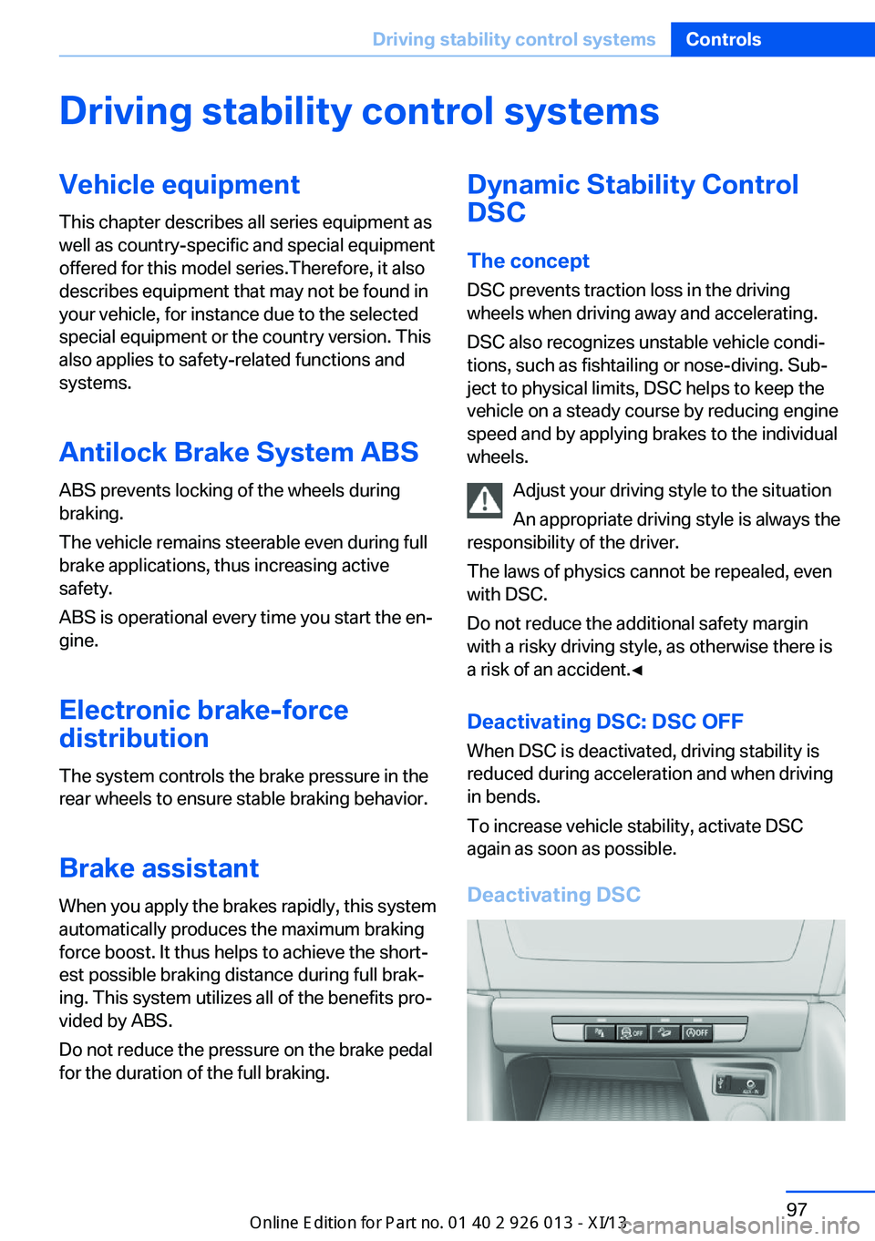
Deactivating DSC: DSC OFF When DSC is deactivated, driving stability is
reduced during acceleration and when driving
in bends.
To increase vehicle stability, activate DSC
again as soon as possible.
Deactivating DSCSeite 97Driving stability control systemsControls97
Online Edition for Part no. 01 40 2 911 269 - VI/13