Dtc BMW X1 2013 E84 Owner's Manual
[x] Cancel search | Manufacturer: BMW, Model Year: 2013, Model line: X1, Model: BMW X1 2013 E84Pages: 299, PDF Size: 6.66 MB
Page 19 of 299
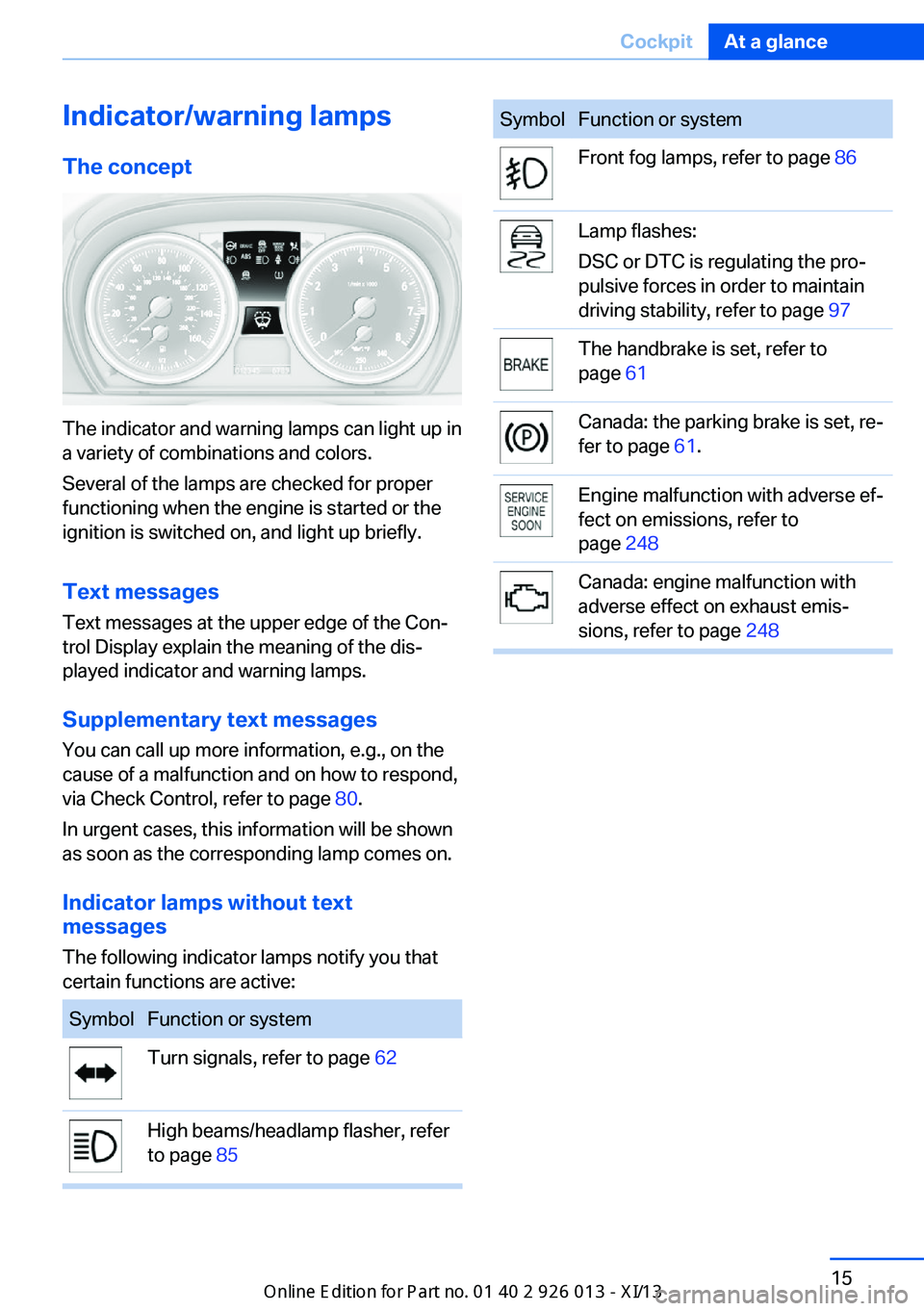
Indicator/warning lampsThe concept
The indicator and warning lamps can light up in
a variety of combinations and colors.
Several of the lamps are checked for proper
functioning when the engine is started or the
ignition is switched on, and light up briefly.
Text messages Text messages at the upper edge of the Con‐
trol Display explain the meaning of the dis‐
played indicator and warning lamps.
Supplementary text messages
You can call up more information, e.g., on the
cause of a malfunction and on how to respond,
via Check Control, refer to page 80.
In urgent cases, this information will be shown
as soon as the corresponding lamp comes on.
Indicator lamps without text
messages
The following indicator lamps notify you that
certain functions are active:
SymbolFunction or systemTurn signals, refer to page 62High beams/headlamp flasher, refer
to page 85SymbolFunction or systemFront fog lamps, refer to page 86Lamp flashes:
DSC or DTC is regulating the pro‐
pulsive forces in order to maintain
driving stability, refer to page 97The handbrake is set, refer to
page 61Canada: the parking brake is set, re‐
fer to page 61.Engine malfunction with adverse ef‐
fect on emissions, refer to
page 248Canada: engine malfunction with
adverse effect on exhaust emis‐
sions, refer to page 248Seite 15CockpitAt a glance15
Online Edition for Part no. 01 40 2 911 269 - VI/13
Page 20 of 299
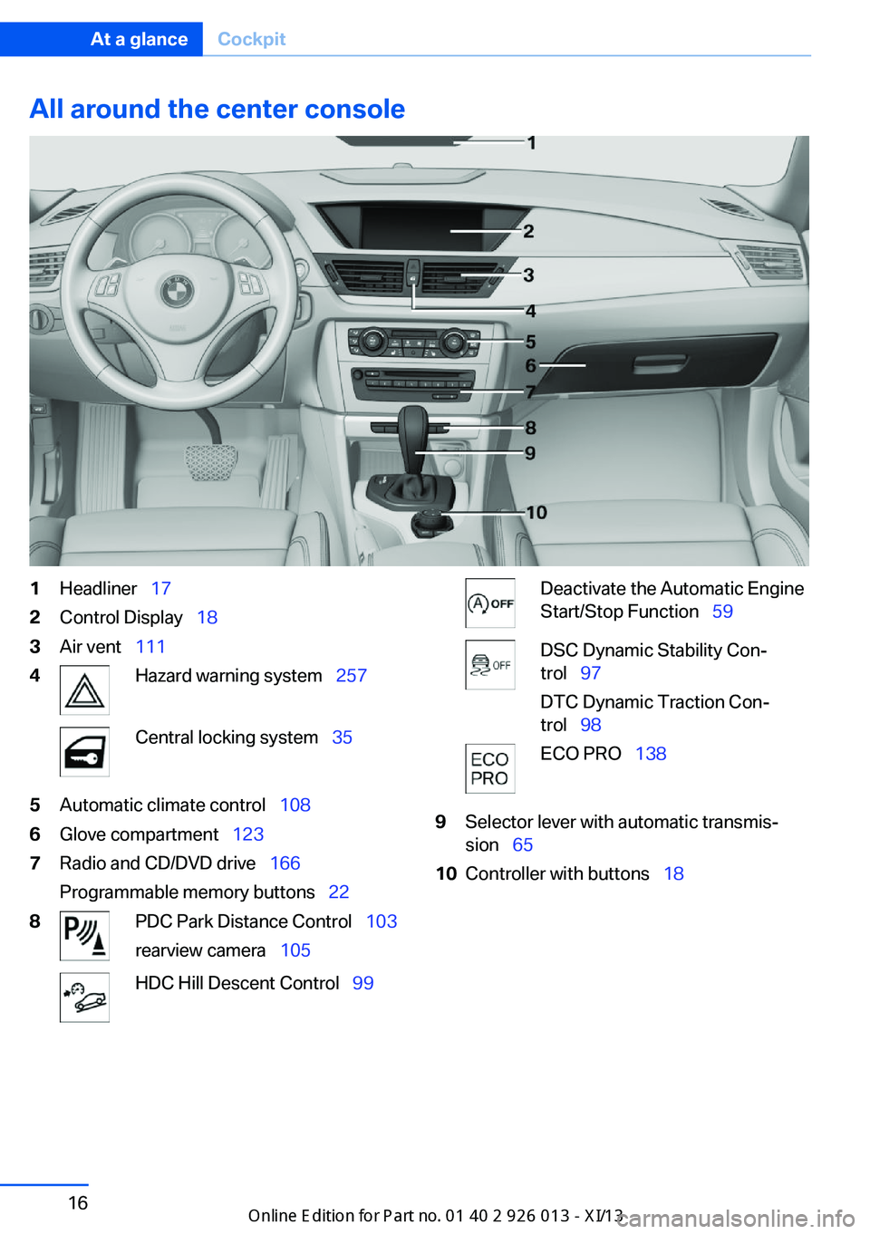
All around the center console1Headliner 172Control Display 183Air vent 1114Hazard warning system 257Central locking system 355Automatic climate control 1086Glove compartment 1237Radio and CD/DVD drive 166
Programmable memory buttons 228PDC Park Distance Control 103
rearview camera 105HDC Hill Descent Control 99Deactivate the Automatic Engine
Start/Stop Function 59DSC Dynamic Stability Con‐
trol 97
DTC Dynamic Traction Con‐
trol 98ECO PRO 1389Selector lever with automatic transmis‐
sion 6510Controller with buttons 18Seite 16At a glanceCockpit16
Online Edition for Part no. 01 40 2 911 269 - VI/13
Page 102 of 299
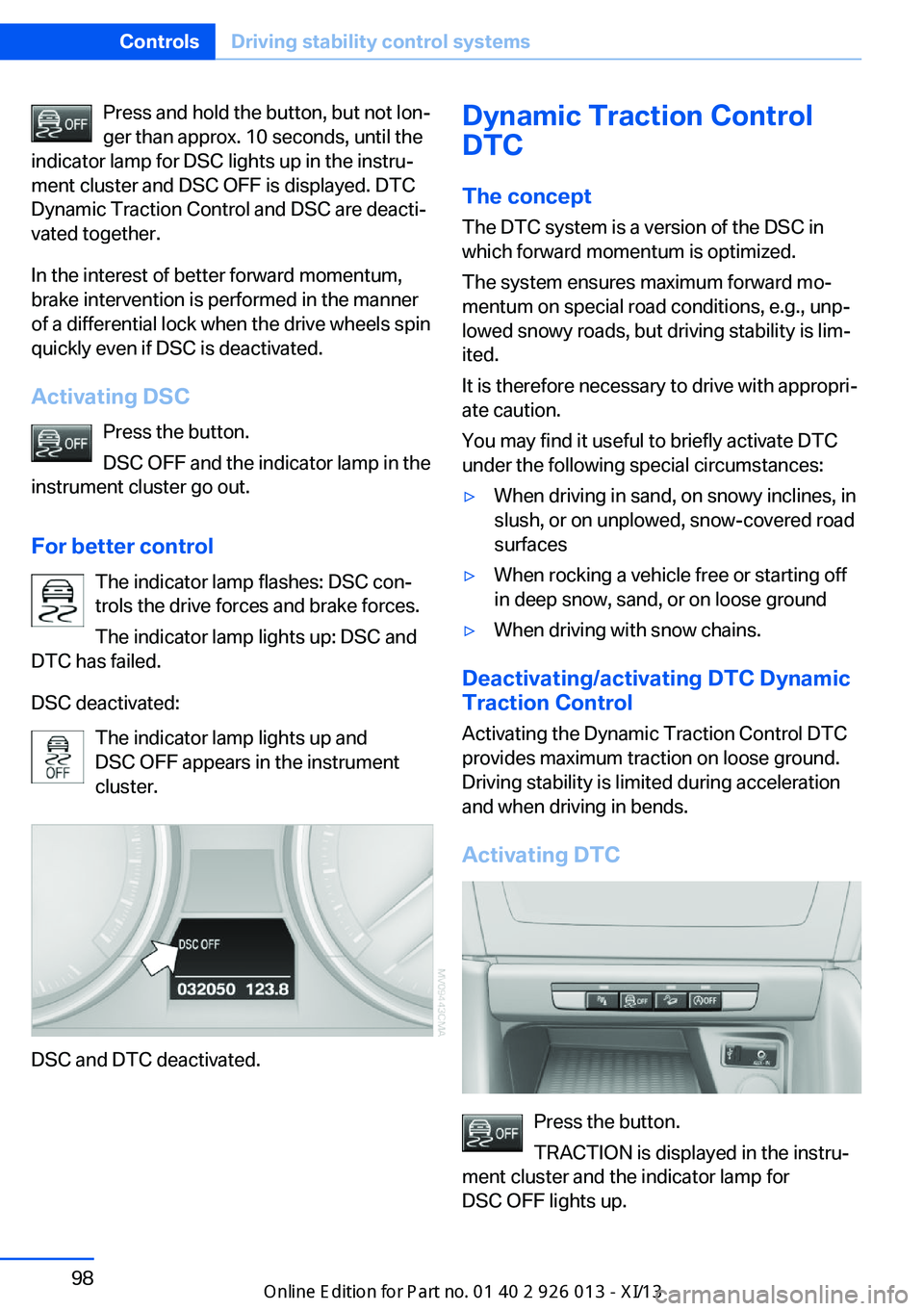
Press and hold the button, but not lon‐
ger than approx. 10 seconds, until the
indicator lamp for DSC lights up in the instru‐
ment cluster and DSC OFF is displayed. DTC
Dynamic Traction Control and DSC are deacti‐
vated together.
In the interest of better forward momentum,
brake intervention is performed in the manner
of a differential lock when the drive wheels spin
quickly even if DSC is deactivated.
Activating DSC Press the button.
DSC OFF and the indicator lamp in the
instrument cluster go out.
For better control The indicator lamp flashes: DSC con‐
trols the drive forces and brake forces.
The indicator lamp lights up: DSC and
DTC has failed.
DSC deactivated: The indicator lamp lights up and
DSC OFF appears in the instrument
cluster.
DSC and DTC deactivated.
Dynamic Traction Control
DTC
The concept The DTC system is a version of the DSC in
which forward momentum is optimized.
The system ensures maximum forward mo‐
mentum on special road conditions, e.g., unp‐
lowed snowy roads, but driving stability is lim‐
ited.
It is therefore necessary to drive with appropri‐
ate caution.
You may find it useful to briefly activate DTC
under the following special circumstances:▷When driving in sand, on snowy inclines, in
slush, or on unplowed, snow-covered road
surfaces▷When rocking a vehicle free or starting off
in deep snow, sand, or on loose ground▷When driving with snow chains.
Deactivating/activating DTC Dynamic
Traction Control
Activating the Dynamic Traction Control DTC
provides maximum traction on loose ground.
Driving stability is limited during acceleration
and when driving in bends.
Activating DTC
Press the button.
TRACTION is displayed in the instru‐
ment cluster and the indicator lamp for
DSC OFF lights up.
Seite 98ControlsDriving stability control systems98
Online Edition for Part no. 01 40 2 911 269 - VI/13
Page 103 of 299
Deactivating DTCPress the button again.
TRACTION and the indicator lamp in
the instrument cluster go out.
For better control The indicator lamp flashes: DTC con‐
trols the drive forces and brake forces.
The indicator lamp lights up: DSC and
DTC has failed.
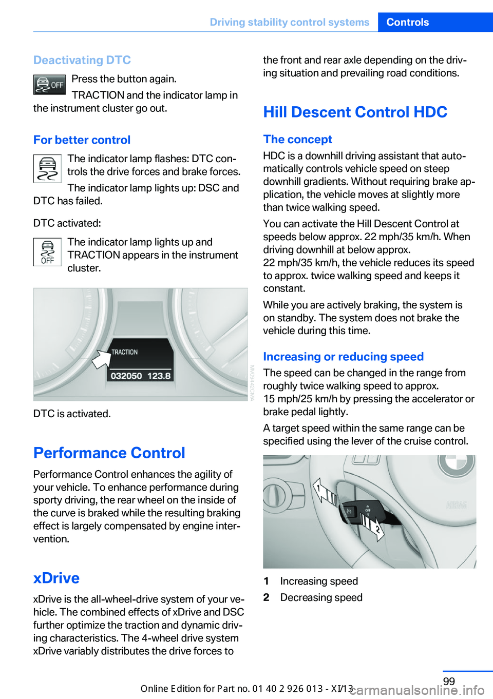
DTC activated: The indicator lamp lights up and
TRACTION appears in the instrument
cluster.
DTC is activated.
Performance Control
Performance Control enhances the agility of
your vehicle. To enhance performance during
sporty driving, the rear wheel on the inside of
the curve is braked while the resulting braking
effect is largely compensated by engine inter‐
vention.
xDrivexDrive is the all-wheel-drive system of your ve‐
hicle. The combined effects of xDrive and DSC
further optimize the traction and dynamic driv‐
ing characteristics. The 4-wheel drive system
xDrive variably distributes the drive forces to
the front and rear axle depending on the driv‐
ing situation and prevailing road conditions.
Hill Descent Control HDC
The concept HDC is a downhill driving assistant that auto‐
matically controls vehicle speed on steep
downhill gradients. Without requiring brake ap‐
plication, the vehicle moves at slightly more
than twice walking speed.
You can activate the Hill Descent Control at
speeds below approx. 22 mph/35 km/h. When
driving downhill at below approx.
22 mph/35 km/h, the vehicle reduces its speed
to approx. twice walking speed and keeps it
constant.
While you are actively braking, the system is
on standby. The system does not brake the
vehicle during this time.
Increasing or reducing speed
The speed can be changed in the range from
roughly twice walking speed to approx.
15 mph/25 km/h by pressing the accelerator or
brake pedal lightly.
A target speed within the same range can be
specified using the lever of the cruise control.1Increasing speed2Decreasing speedSeite 99Driving stability control systemsControls99
Online Edition for Part no. 01 40 2 911 269 - VI/13
Page 106 of 299
The system stores and maintains the speed.
Accelerating using the lever Accelerating slightly:
Press the lever to the resistance point, arrow 1,
until the desired speed is reached.
Accelerating significantly:
Press the lever beyond the resistance point,
arrow 1, until the desired speed is reached.
The vehicle accelerates without pressure on
the accelerator pedal. The system stores and
maintains the speed.
Decreasing speed
Repeatedly pull the lever to the resistance
point or beyond, arrow 2, until the desired
speed is displayed.▷Each time the lever is pulled to the resist‐
ance point, the desired speed is decreased
by approx. 1 mph/1 km/h.▷Each time the lever is pulled beyond the
resistance point, the desired speed is re‐
duced by up to 5 mph/10 km/h until the
minimum speed of 20 mph/30 km/h is ach‐
ieved.
The system stores and maintains the speed.
Deactivating cruise control
Push the lever upwards or downwards, ar‐
row 3.
The displays in the speedometer go out.
In addition, the system is automatically deacti‐
vated when:
▷The brakes are applied.▷Selector lever position N is engaged or
transmission position D is disengaged.▷When DTC is activated or DSC is deacti‐
vated.▷When DSC or ABS is intervening.
Cruise control is not deactivated by depressing
the accelerator pedal. Once the accelerator
pedal is released, the stored speed is achieved
again and maintained.
Warning lamp The warning lamp comes on when
cruise control has been deactivated
as a result of DSC intervention, for
example. A message appears on the Control
Display.
Resuming a speed stored beforehand Press the button, arrow 4. The last stored
speed is resumed and maintained.
In the following cases, the stored speed value
is deleted and cannot be called up again:▷When driving stability control systems in‐
tervene.▷When selector lever position N is engaged
or transmission position D is disengaged.▷When the ignition is switched off.
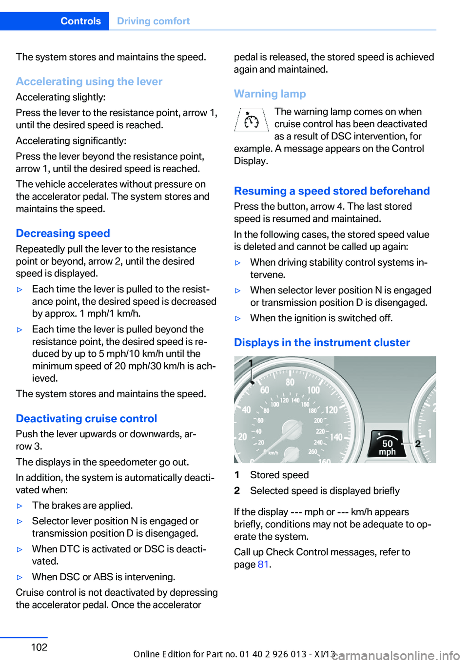
Displays in the instrument cluster
1Stored speed2Selected speed is displayed briefly
If the display --- mph or --- km/h appears
briefly, conditions may not be adequate to op‐
erate the system.
Call up Check Control messages, refer to
page 81.
Seite 102ControlsDriving comfort102
Online Edition for Part no. 01 40 2 911 269 - VI/13
Page 137 of 299
▷On bumps and rough roads, avoid contact
between the vehicle body and the ground.
The maximum ground clearance is 8 in‐
ches/20 cm and may vary with the loaded
cargo.▷When driving through water, do not exceed
the maximum water height of 12 in‐
ches/30 cm and drive at walking speed.▷After driving through water, press on the
brake pedal several times at low speeds to
dry the brakes.▷Depending on the prevailing terrain, acti‐
vate Dynamic Traction Control DTC, refer
to page 98, briefly.▷When the wheels spin, accelerate to ena‐
ble the driving stability control systems to
distribute the drive force to the individual
wheels.
After driving on poor roads
Adhere to the following points to ensure vehi‐
cle safety:
▷Remove excessive accumulations of dirt
and mud from the vehicle body.▷Clear mud, snow, ice, etc., from the wheels
and tires and check for damage.Seite 133Things to remember when drivingDriving tips133
Online Edition for Part no. 01 40 2 911 269 - VI/13
Page 245 of 299
The wheels are composed of special rims and
tires that are self-supporting, to a limited de‐
gree.
The support of the sidewall allows the tire to
remain drivable to a restricted degree in the
event of a pressure loss.
Driving with a damaged tire:▷Flat Tire Monitor FTM, refer to page 91▷Tire Pressure Monitor TPM, refer to
page 93
Changing run-flat tires
For your own safety, only use run-flat tires. No
spare tire is available in the case of a flat tire.
Your service center will be glad to advise you.
Snow chains
Only certain fine-link snow chains have been
tested by BMW, classified as safe for use and
recommended. Consult your service center for
more information.
Snow chains must be mounted in pairs and on the rear wheels only.
Observe the manufacturer's instructions when
mounting snow chains. Do not exceed a speed
of 30 mph/50 km/h when using snow chains.
Do not initialize the Flat Tire Monitor if snow
chains are mounted; otherwise, the instrument
might issue an incorrect reading.
When driving with snow chains, it can be bene‐
ficial to temporarily activate DTC, refer to
page 98.
Seite 241Wheels and tiresMobility241
Online Edition for Part no. 01 40 2 911 269 - VI/13
Page 287 of 299
Cruise control 101
Cruise control– Malfunction 103
Cupholder 125
Curb weight, refer to Weights 270
Current fuel consumption 72
Current location, storing 146
Curve lights, refer to Adaptive Light Control 84
D
Dashboard lighting, refer to Instrument lighting 87
Dashboard, refer to Cock‐ pit 12
Data, technical 270
Date
– Date format 77– Setting 76
Daytime running lights 84
Daytime running lights, bulb replacement 252
Defroster
– Rear window 111
Destination entry via the ad‐
dress book 146
Destination guidance 153
Destination guidance with in‐ termediate destinations 151
Destination input, naviga‐ tion 144
Digital clock 71
Digital compass 115
Digital radio 167
Dimming mirrors 50
Directional indicators, refer to Turn signals 62
Display lighting, refer to In‐ strument lighting 87
Displays and controls 12
Displays, care 266
Displays, cleaning 266
Displays, refer to Instrument cluster 14
Disposal, coolant 246
Disposal, vehicle battery 255
Distance warning, refer to Park Distance Control
PDC 103
Divided rear seat backrest, re‐ fer to Enlarging the cargo
area 118
Divided screen view, split screen 22
Door key, refer to Remote control with integrated
key 30
Door lock 34
Doors, manual operation 34
Doors, unlocking and locking– Confirmation signals 33– From the inside 35– From the outside 32
DOT Quality Grades 237
Downhill control 99
Draft-free ventilation 111
Drive-off assistant 100
Driving away on inclines, refer to Drive-off assistant 100
Driving notes, breaking in 130
Driving notes, general 130
Driving on poor roads 132
Driving stability control sys‐ tems 97
Driving through water 131
Driving tips, refer to Driving notes 130
Dry air, refer to Cooling func‐ tion 110
DSC Dynamic Stability Con‐ trol 97
DTC Dynamic Traction Con‐ trol 98
DTMF suffix dialing 202
DVD/CD 174
DVDs, storing 179
DVD, video 176
Dynamic destination guid‐ ance 160
Dynamic Stability Control DSC 97
Dynamic Traction Control
DTC 98
E
ECO PRO 138
ECO PRO display 138
ECO PRO driving mode 138
ECO PRO mode 138
EfficientDynamics, refer to Saving fuel 137
Electrical malfunction– Door lock 34– Driver's door 34– Fuel filler flap 229– Tailgate 36
Electric seat adjustment 45
Electronic brake-force distri‐ bution 97
Electronic engine oil level check 243
Electronic Stability Program ESP, refer to Dynamic Sta‐
bility Control DSC 97
Emergency activation
– Automatic transmission, re‐
fer to Overriding selector
lever lock 67
Emergency operation
– Door lock, refer to Manual
operation 34
Emergency operation, fuel
filler flap, unlocking man‐
ually 229
Emergency Request 257
Emergency service, refer to Roadside Assistance 258
Energy-conscious driving, re‐ fer to Current fuel consump‐
tion 72
Energy, saving
– Automatic Engine Start/
Stop Function 59
Energy, saving, refer to Sav‐
ing fuel 137
Engine, breaking in 130
Engine compartment 242
Seite 283Everything from A to ZReference283
Online Edition for Part no. 01 40 2 911 269 - VI/13