turn signal BMW X1 2016 F48 User Guide
[x] Cancel search | Manufacturer: BMW, Model Year: 2016, Model line: X1, Model: BMW X1 2016 F48Pages: 242, PDF Size: 7.12 MB
Page 118 of 242
cording to their respective set‐
tings.▷LED lights up orange or goes out respec‐
tive to their individual settings.
Adjust as needed. Individual settings are
stored for the profile currently used.
Press button again:
▷All Intelligent Safety systems are
activated.▷The LED lights up green.
Hold down button:
▷All Intelligent Safety systems are
turned off.▷The LED goes out.
Display in the instrument cluster
▷Lines: system is activated.▷Arrows: at least one lane marking
was detected and warnings can be
issued.
Issued warning
If you leave the lane and if a lane marking has
been detected, the steering wheel begins vi‐
brating.
If the turn signal is set before changing the
lane, a warning is not issued.
End of warning
The warning is canceled in the following situa‐
tions:
▷Automatically after approx. 3 seconds.▷When returning to your own lane.▷When braking hard.▷When using the turn signal.
System limits
The system may not be fully functional in the
following situations:
▷In heavy fog, rain or snowfall.▷In the event of missing, worn, poorly visi‐
ble, merging, diverging, or multiple lane
markings such as in construction areas.▷When lane markings are covered in snow,
ice, dirt or water.▷In tight curves or on narrow lanes.▷When the lane markings are covered by
objects.▷When driving very close to the vehicle in
front of you.▷When driving toward bright lights.▷When the windshield in front of the interior
rearview mirror is fogged over, dirty or cov‐
ered with stickers, etc.▷During calibration of the camera immedi‐
ately after vehicle delivery.
Brake force display
The concept
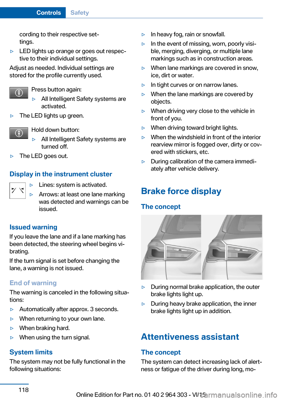
▷During normal brake application, the outer
brake lights light up.▷During heavy brake application, the inner
brake lights light up in addition.
Attentiveness assistant
The concept The system can detect increasing lack of alert‐
ness or fatigue of the driver during long, mo‐
Seite 118ControlsSafety118
Online Edition for Part no. 01 40 2 964 303 - VI/15
Page 136 of 242
Switching on/off
Switching on automatically PDC switches on automatically in the following
situations:▷If selector lever position R is engaged
when the engine is running.
The rearview camera also switches on.▷If equipped with front PDC: when obsta‐
cles are detected behind or in front of the
vehicle by PDC and the speed is slower
than approx. 2.5 mph/4 km/h.
You may turn off automatic activation:
1."Settings"2."Parking"3.Select setting.
Settings are stored for the profile currently
used.
Automatic deactivation during forward
travel
The system switches off when a certain driving
distance or speed is exceeded.
Switch the system back on if needed.
With front PDC: switching on/off
manually
Press button.
▷On: the LED lights up.▷Off: the LED goes out.
The rearview camera image is displayed when
the reverse gear is engaged by pressing the
button.
Display
Signal tones When approaching an object, an intermittent
sound indicates the position of the object. E. g.
if an object is detected to the left rear of the
vehicle, a signal tone sounds from the left rear
speaker.
The shorter the distance to the object, the
shorter the intervals.
If the distance to a detected object is less than
approx. 10 in/25 cm, a continuous tone is
sounded.
With front PDC: if objects are located both in
front of and behind the vehicle, an alternating
continuous signal is sounded.
The signal tone is switched off, when selector
lever position P is engaged on vehicles with
Steptronic transmission.
Volume
The ratio of the PDC signal tone volume to the
entertainment volume can be adjusted.1."Multimedia", "Radio" or "Settings"2."Tone"3."Volume settings"4."PDC"5.Turn the controller until the desired setting
is selected.6.Press the controller.
Settings are stored for the profile currently
used.
Visual warning
The approach of the vehicle to an object can
be shown on the Control Display. Objects that
are farther away are already displayed on the
Control Display before a signal sounds.
A display appears as soon as Park Distance
Control (PDC) is activated.
The range of the sensors is represented in the
colors green, yellow and red.
When the image of the rearview camera is dis‐
played, the switch can be made to PDC:
"Rear view camera"
Seite 136ControlsDriving comfort136
Online Edition for Part no. 01 40 2 964 303 - VI/15
Page 141 of 242
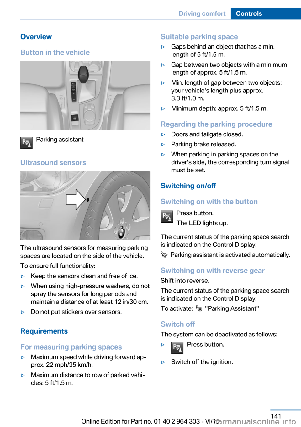
Overview
Button in the vehicle
Parking assistant
Ultrasound sensors
The ultrasound sensors for measuring parking
spaces are located on the side of the vehicle.
To ensure full functionality:
▷Keep the sensors clean and free of ice.▷When using high-pressure washers, do not
spray the sensors for long periods and
maintain a distance of at least 12 in/30 cm.▷Do not put stickers over sensors.
Requirements
For measuring parking spaces
▷Maximum speed while driving forward ap‐
prox. 22 mph/35 km/h.▷Maximum distance to row of parked vehi‐
cles: 5 ft/1.5 m.Suitable parking space▷Gaps behind an object that has a min.
length of 5 ft/1.5 m.▷Gap between two objects with a minimum
length of approx. 5 ft/1.5 m.▷Min. length of gap between two objects:
your vehicle's length plus approx.
3.3 ft/1.0 m.▷Minimum depth: approx. 5 ft/1.5 m.
Regarding the parking procedure
▷Doors and tailgate closed.▷Parking brake released.▷When parking in parking spaces on the
driver's side, the corresponding turn signal
must be set.
Switching on/off
Switching on with the button Press button.
The LED lights up.
The current status of the parking space search
is indicated on the Control Display.
Parking assistant is activated automatically.
Switching on with reverse gear
Shift into reverse.
The current status of the parking space search
is indicated on the Control Display.
To activate:
"Parking Assistant"
Switch off
The system can be deactivated as follows:
▷Press button.▷Switch off the ignition.Seite 141Driving comfortControls141
Online Edition for Part no. 01 40 2 964 303 - VI/15
Page 207 of 242
A spare lamp box is available from a dealer’s
service center or another qualified service cen‐
ter or repair shop.
WARNING
Bulbs can get hot during operation. Con‐
tact with the bulbs can cause burns. There is
risk of injuries. Only change bulbs after they
have cooled off.◀
WARNING
Work on switched-on lighting systems
can cause short circuits. There is risk of inju‐
ries or risk of property damage. When working
on the lighting system, switch off the lamps in
question. If necessary, heed the bulb manufac‐
turer's instructions.◀
CAUTION
Contaminated bulbs reduce their service
life. There is risk of property damage. Do not
hold new bulbs with your bare hands. Use a
clean cloth or something similar, or hold the
bulb by its base.◀
Light-emitting diodes (LEDs)
Some items of equipment use light-emitting
diodes installed behind a cover as a light
source.
These light-emitting diodes, which are related
to conventional lasers, are officially designated
as Class 1 light-emitting diodes.
WARNING
Too intensive brightness can irritate or
damage the retina of the eye. There is risk of
injuries. Do not look directly into the headlights
or other light sources for an extended period of
time. Do not remove the LED covers.◀
Headlight glass
Condensation can form on the inside of the ex‐
ternal lights in cool or humid weather. When
driving with the lights switched on, the con‐
densation evaporates after a short time. The
headlight glass does not need to be changed.If despite driving with the lights switched on,
increasing humidity forms, e. g. water droplets
in the lamp, the manufacturer of your vehicle
recommends having it checked by a dealer’s
service center or another qualified service cen‐
ter or repair shop.
Headlight setting
The headlight adjustments can be affected by
changing lights and bulbs. After the headlight
adjustment was changed, have it checked and,
if necessary, corrected by a dealer’s service
center or another qualified service center or re‐
pair shop.
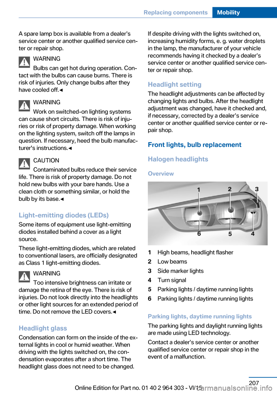
Front lights, bulb replacement
Halogen headlights Overview1High beams, headlight flasher2Low beams3Side marker lights4Turn signal5Parking lights / daytime running lights6Parking lights / daytime running lights
Parking lights, daytime running lights
The parking lights and daylight running lights
are made using LED technology.
Contact a dealer’s service center or another
qualified service center or repair shop in the
event of a malfunction.
Seite 207Replacing componentsMobility207
Online Edition for Part no. 01 40 2 964 303 - VI/15
Page 208 of 242
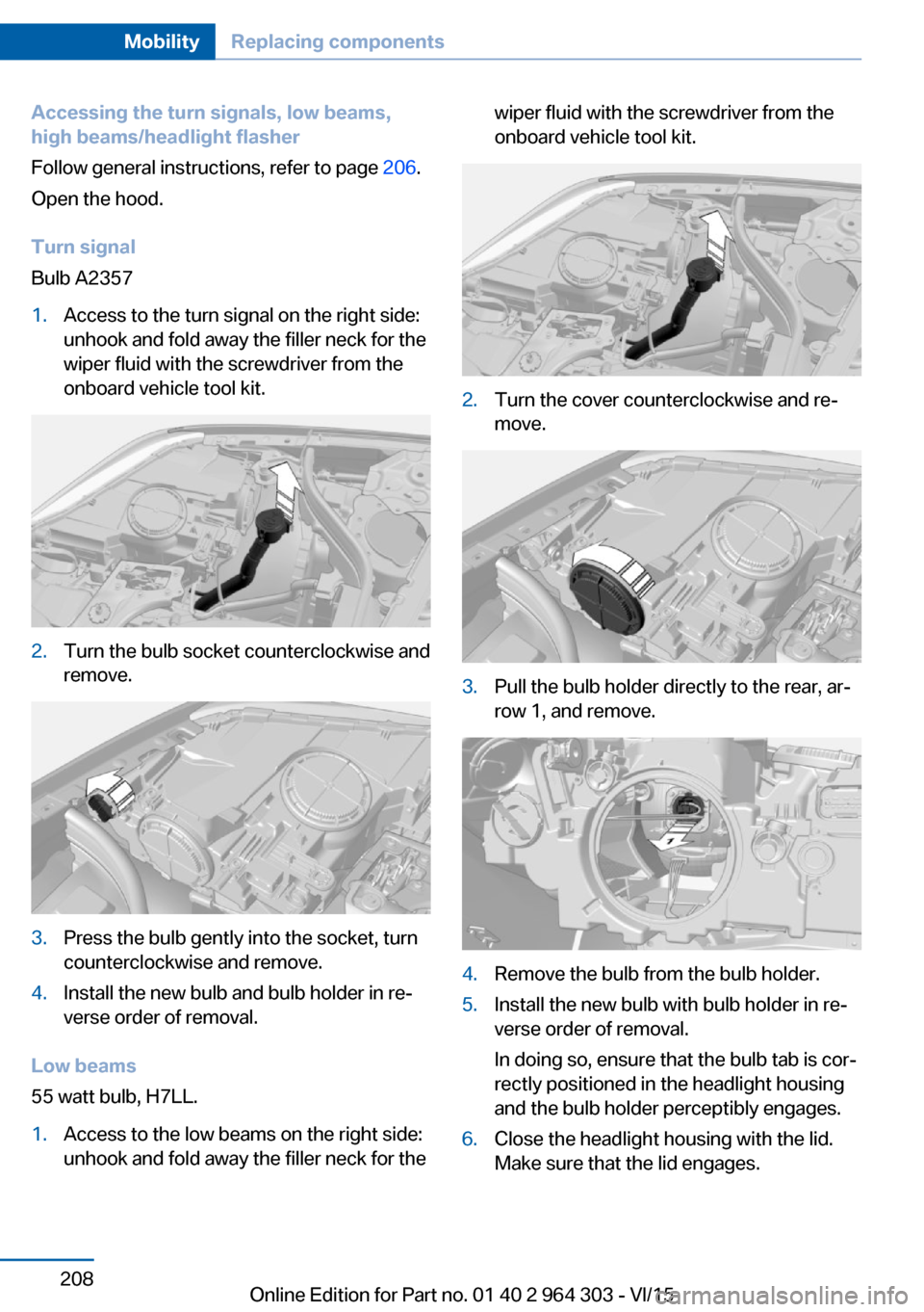
Accessing the turn signals, low beams,
high beams/headlight flasher
Follow general instructions, refer to page 206.
Open the hood.
Turn signal
Bulb A23571.Access to the turn signal on the right side:
unhook and fold away the filler neck for the
wiper fluid with the screwdriver from the
onboard vehicle tool kit.2.Turn the bulb socket counterclockwise and
remove.3.Press the bulb gently into the socket, turn
counterclockwise and remove.4.Install the new bulb and bulb holder in re‐
verse order of removal.
Low beams
55 watt bulb, H7LL.
1.Access to the low beams on the right side:
unhook and fold away the filler neck for thewiper fluid with the screwdriver from the
onboard vehicle tool kit.2.Turn the cover counterclockwise and re‐
move.3.Pull the bulb holder directly to the rear, ar‐
row 1, and remove.4.Remove the bulb from the bulb holder.5.Install the new bulb with bulb holder in re‐
verse order of removal.
In doing so, ensure that the bulb tab is cor‐
rectly positioned in the headlight housing
and the bulb holder perceptibly engages.6.Close the headlight housing with the lid.
Make sure that the lid engages.Seite 208MobilityReplacing components208
Online Edition for Part no. 01 40 2 964 303 - VI/15
Page 209 of 242
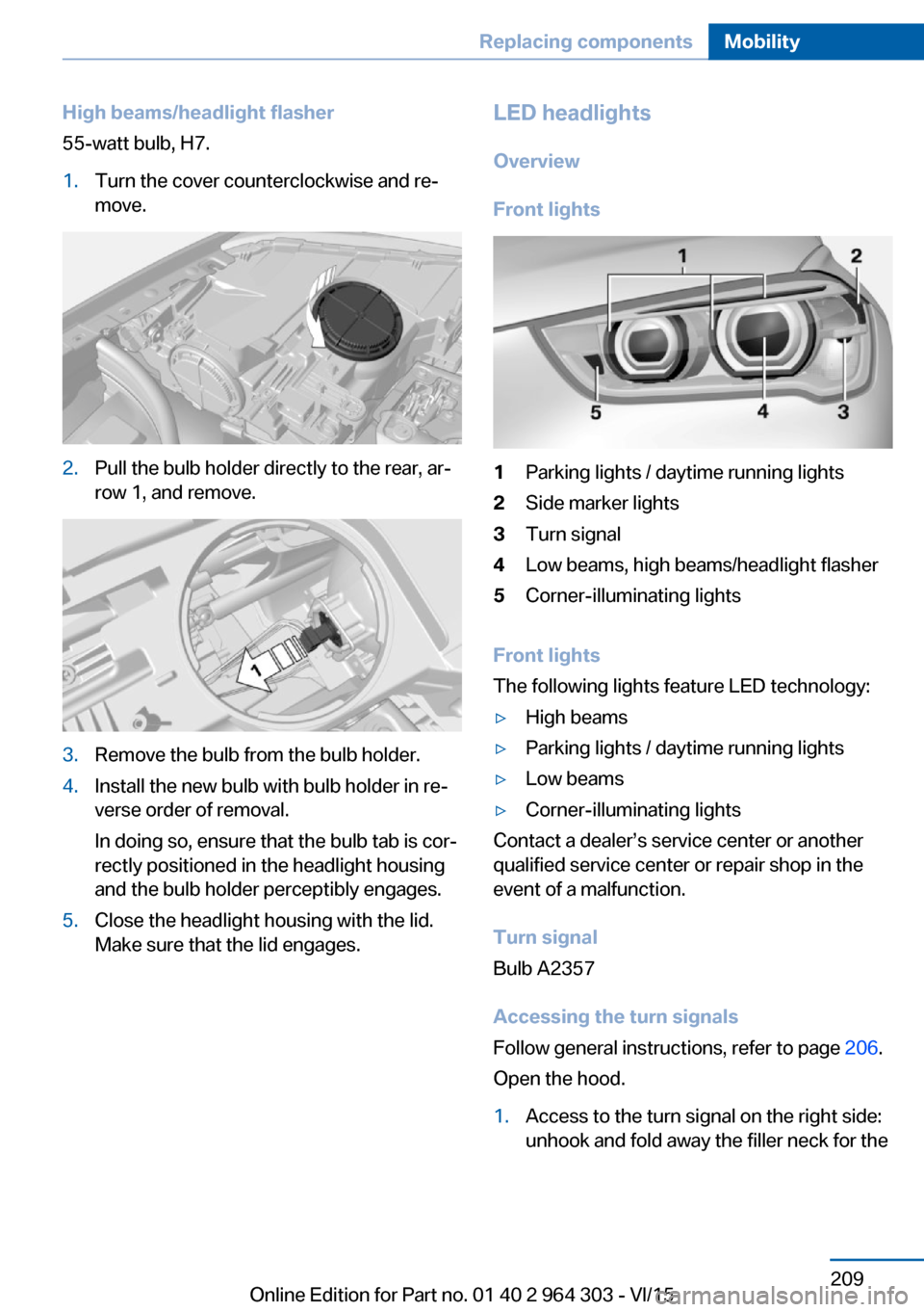
High beams/headlight flasher
55-watt bulb, H7.1.Turn the cover counterclockwise and re‐
move.2.Pull the bulb holder directly to the rear, ar‐
row 1, and remove.3.Remove the bulb from the bulb holder.4.Install the new bulb with bulb holder in re‐
verse order of removal.
In doing so, ensure that the bulb tab is cor‐
rectly positioned in the headlight housing
and the bulb holder perceptibly engages.5.Close the headlight housing with the lid.
Make sure that the lid engages.LED headlights
Overview
Front lights1Parking lights / daytime running lights2Side marker lights3Turn signal4Low beams, high beams/headlight flasher5Corner-illuminating lights
Front lights
The following lights feature LED technology:
▷High beams▷Parking lights / daytime running lights▷Low beams▷Corner-illuminating lights
Contact a dealer’s service center or another
qualified service center or repair shop in the
event of a malfunction.
Turn signal
Bulb A2357
Accessing the turn signals
Follow general instructions, refer to page 206.
Open the hood.
1.Access to the turn signal on the right side:
unhook and fold away the filler neck for theSeite 209Replacing componentsMobility209
Online Edition for Part no. 01 40 2 964 303 - VI/15
Page 211 of 242
Turn signal in exterior mirrorThe turn signals in the exterior mirrors feature
LED technology. Contact a dealer’s service
center or another qualified service center or re‐
pair shop in the event of a malfunction.
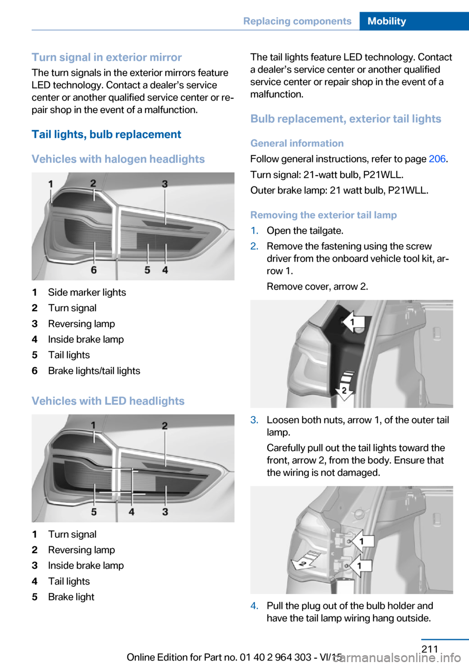
Tail lights, bulb replacement
Vehicles with halogen headlights1Side marker lights2Turn signal3Reversing lamp4Inside brake lamp5Tail lights6Brake lights/tail lights
Vehicles with LED headlights
1Turn signal2Reversing lamp3Inside brake lamp4Tail lights5Brake lightThe tail lights feature LED technology. Contact
a dealer’s service center or another qualified
service center or repair shop in the event of a
malfunction.
Bulb replacement, exterior tail lights
General information
Follow general instructions, refer to page 206.
Turn signal: 21-watt bulb, P21WLL.
Outer brake lamp: 21 watt bulb, P21WLL.
Removing the exterior tail lamp1.Open the tailgate.2.Remove the fastening using the screw
driver from the onboard vehicle tool kit, ar‐
row 1.
Remove cover, arrow 2.3.Loosen both nuts, arrow 1, of the outer tail
lamp.
Carefully pull out the tail lights toward the
front, arrow 2, from the body. Ensure that
the wiring is not damaged.4.Pull the plug out of the bulb holder and
have the tail lamp wiring hang outside.Seite 211Replacing componentsMobility211
Online Edition for Part no. 01 40 2 964 303 - VI/15
Page 212 of 242
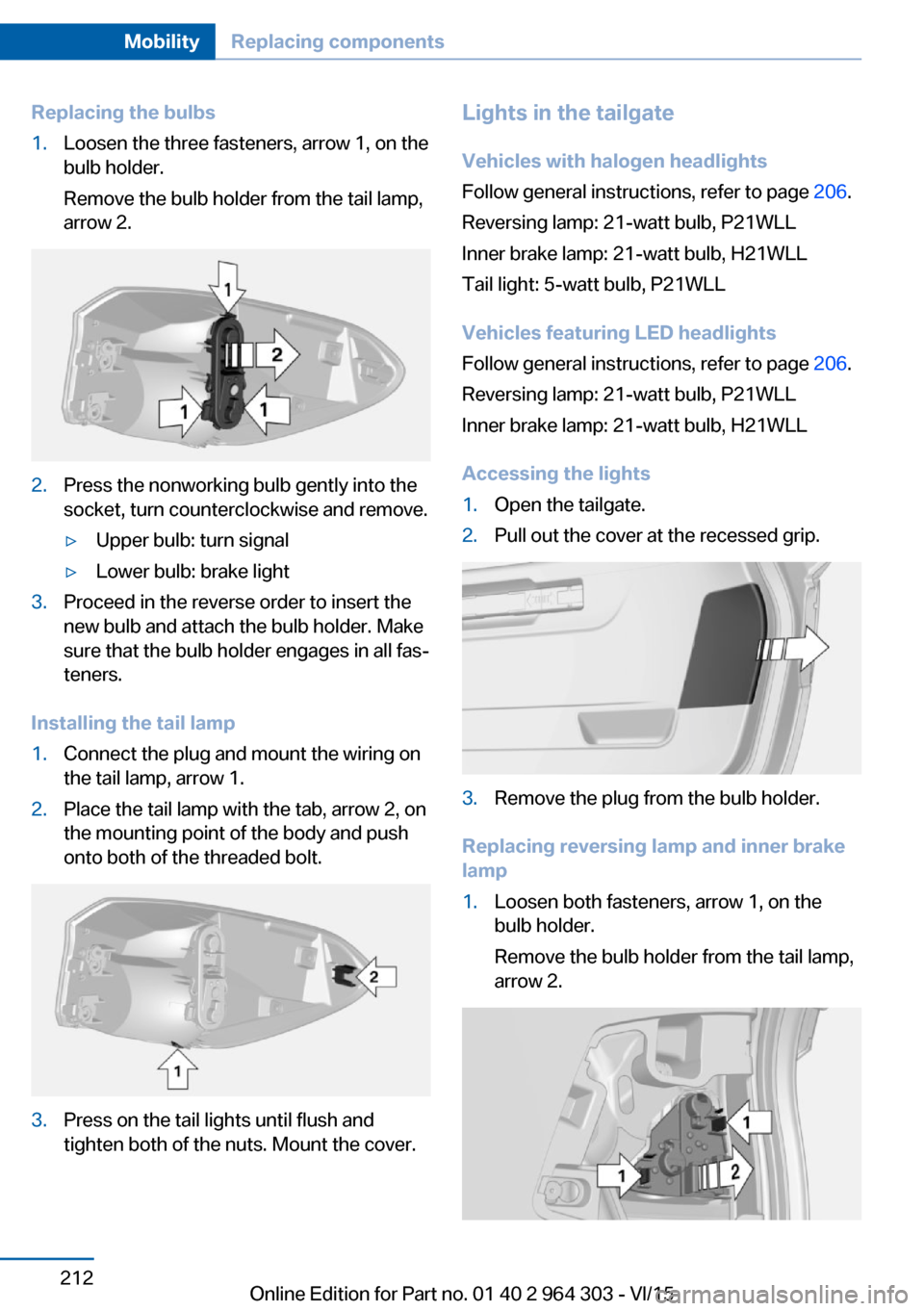
Replacing the bulbs1.Loosen the three fasteners, arrow 1, on the
bulb holder.
Remove the bulb holder from the tail lamp,
arrow 2.2.Press the nonworking bulb gently into the
socket, turn counterclockwise and remove.▷Upper bulb: turn signal▷Lower bulb: brake light3.Proceed in the reverse order to insert the
new bulb and attach the bulb holder. Make
sure that the bulb holder engages in all fas‐
teners.
Installing the tail lamp
1.Connect the plug and mount the wiring on
the tail lamp, arrow 1.2.Place the tail lamp with the tab, arrow 2, on
the mounting point of the body and push
onto both of the threaded bolt.3.Press on the tail lights until flush and
tighten both of the nuts. Mount the cover.Lights in the tailgate
Vehicles with halogen headlights
Follow general instructions, refer to page 206.
Reversing lamp: 21-watt bulb, P21WLL
Inner brake lamp: 21-watt bulb, H21WLL
Tail light: 5-watt bulb, P21WLL
Vehicles featuring LED headlights
Follow general instructions, refer to page 206.
Reversing lamp: 21-watt bulb, P21WLL
Inner brake lamp: 21-watt bulb, H21WLL
Accessing the lights1.Open the tailgate.2.Pull out the cover at the recessed grip.3.Remove the plug from the bulb holder.
Replacing reversing lamp and inner brake
lamp
1.Loosen both fasteners, arrow 1, on the
bulb holder.
Remove the bulb holder from the tail lamp,
arrow 2.Seite 212MobilityReplacing components212
Online Edition for Part no. 01 40 2 964 303 - VI/15
Page 233 of 242
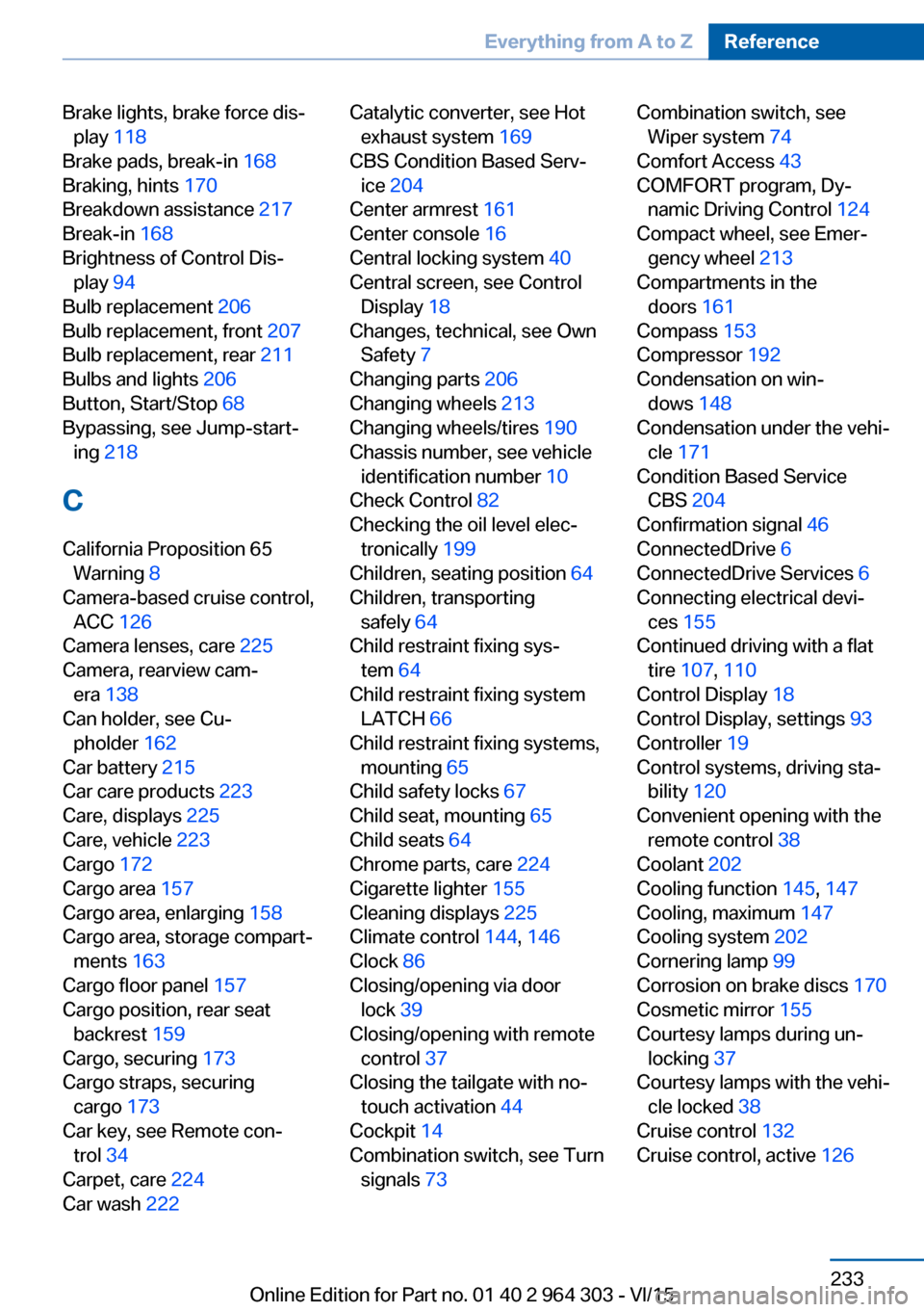
Brake lights, brake force dis‐play 118
Brake pads, break-in 168
Braking, hints 170
Breakdown assistance 217
Break-in 168
Brightness of Control Dis‐ play 94
Bulb replacement 206
Bulb replacement, front 207
Bulb replacement, rear 211
Bulbs and lights 206
Button, Start/Stop 68
Bypassing, see Jump-start‐ ing 218
C
California Proposition 65 Warning 8
Camera-based cruise control, ACC 126
Camera lenses, care 225
Camera, rearview cam‐ era 138
Can holder, see Cu‐ pholder 162
Car battery 215
Car care products 223
Care, displays 225
Care, vehicle 223
Cargo 172
Cargo area 157
Cargo area, enlarging 158
Cargo area, storage compart‐ ments 163
Cargo floor panel 157
Cargo position, rear seat backrest 159
Cargo, securing 173
Cargo straps, securing cargo 173
Car key, see Remote con‐ trol 34
Carpet, care 224
Car wash 222 Catalytic converter, see Hot
exhaust system 169
CBS Condition Based Serv‐ ice 204
Center armrest 161
Center console 16
Central locking system 40
Central screen, see Control Display 18
Changes, technical, see Own Safety 7
Changing parts 206
Changing wheels 213
Changing wheels/tires 190
Chassis number, see vehicle identification number 10
Check Control 82
Checking the oil level elec‐ tronically 199
Children, seating position 64
Children, transporting safely 64
Child restraint fixing sys‐ tem 64
Child restraint fixing system LATCH 66
Child restraint fixing systems, mounting 65
Child safety locks 67
Child seat, mounting 65
Child seats 64
Chrome parts, care 224
Cigarette lighter 155
Cleaning displays 225
Climate control 144, 146
Clock 86
Closing/opening via door lock 39
Closing/opening with remote control 37
Closing the tailgate with no- touch activation 44
Cockpit 14
Combination switch, see Turn signals 73 Combination switch, see
Wiper system 74
Comfort Access 43
COMFORT program, Dy‐ namic Driving Control 124
Compact wheel, see Emer‐ gency wheel 213
Compartments in the doors 161
Compass 153
Compressor 192
Condensation on win‐ dows 148
Condensation under the vehi‐ cle 171
Condition Based Service CBS 204
Confirmation signal 46
ConnectedDrive 6
ConnectedDrive Services 6
Connecting electrical devi‐ ces 155
Continued driving with a flat tire 107 , 110
Control Display 18
Control Display, settings 93
Controller 19
Control systems, driving sta‐ bility 120
Convenient opening with the remote control 38
Coolant 202
Cooling function 145, 147
Cooling, maximum 147
Cooling system 202
Cornering lamp 99
Corrosion on brake discs 170
Cosmetic mirror 155
Courtesy lamps during un‐ locking 37
Courtesy lamps with the vehi‐ cle locked 38
Cruise control 132
Cruise control, active 126 Seite 233Everything from A to ZReference233
Online Edition for Part no. 01 40 2 964 303 - VI/15
Page 234 of 242
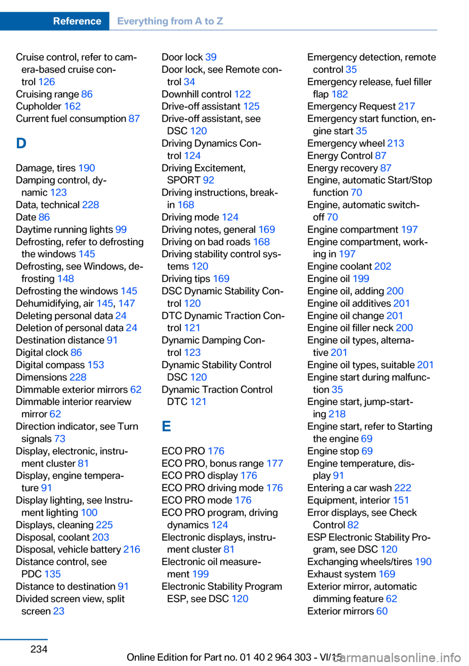
Cruise control, refer to cam‐era-based cruise con‐
trol 126
Cruising range 86
Cupholder 162
Current fuel consumption 87
D
Damage, tires 190
Damping control, dy‐ namic 123
Data, technical 228
Date 86
Daytime running lights 99
Defrosting, refer to defrosting the windows 145
Defrosting, see Windows, de‐ frosting 148
Defrosting the windows 145
Dehumidifying, air 145, 147
Deleting personal data 24
Deletion of personal data 24
Destination distance 91
Digital clock 86
Digital compass 153
Dimensions 228
Dimmable exterior mirrors 62
Dimmable interior rearview mirror 62
Direction indicator, see Turn signals 73
Display, electronic, instru‐ ment cluster 81
Display, engine tempera‐ ture 91
Display lighting, see Instru‐ ment lighting 100
Displays, cleaning 225
Disposal, coolant 203
Disposal, vehicle battery 216
Distance control, see PDC 135
Distance to destination 91
Divided screen view, split screen 23 Door lock 39
Door lock, see Remote con‐ trol 34
Downhill control 122
Drive-off assistant 125
Drive-off assistant, see DSC 120
Driving Dynamics Con‐ trol 124
Driving Excitement, SPORT 92
Driving instructions, break- in 168
Driving mode 124
Driving notes, general 169
Driving on bad roads 168
Driving stability control sys‐ tems 120
Driving tips 169
DSC Dynamic Stability Con‐ trol 120
DTC Dynamic Traction Con‐ trol 121
Dynamic Damping Con‐ trol 123
Dynamic Stability Control DSC 120
Dynamic Traction Control DTC 121
E
ECO PRO 176
ECO PRO, bonus range 177
ECO PRO display 176
ECO PRO driving mode 176
ECO PRO mode 176
ECO PRO program, driving dynamics 124
Electronic displays, instru‐ ment cluster 81
Electronic oil measure‐ ment 199
Electronic Stability Program ESP, see DSC 120 Emergency detection, remote
control 35
Emergency release, fuel filler flap 182
Emergency Request 217
Emergency start function, en‐ gine start 35
Emergency wheel 213
Energy Control 87
Energy recovery 87
Engine, automatic Start/Stop function 70
Engine, automatic switch- off 70
Engine compartment 197
Engine compartment, work‐ ing in 197
Engine coolant 202
Engine oil 199
Engine oil, adding 200
Engine oil additives 201
Engine oil change 201
Engine oil filler neck 200
Engine oil types, alterna‐ tive 201
Engine oil types, suitable 201
Engine start during malfunc‐ tion 35
Engine start, jump-start‐ ing 218
Engine start, refer to Starting the engine 69
Engine stop 69
Engine temperature, dis‐ play 91
Entering a car wash 222
Equipment, interior 151
Error displays, see Check Control 82
ESP Electronic Stability Pro‐ gram, see DSC 120
Exchanging wheels/tires 190
Exhaust system 169
Exterior mirror, automatic dimming feature 62
Exterior mirrors 60 Seite 234ReferenceEverything from A to Z234
Online Edition for Part no. 01 40 2 964 303 - VI/15