jack BMW X1 2016 F48 Owner's Manual
[x] Cancel search | Manufacturer: BMW, Model Year: 2016, Model line: X1, Model: BMW X1 2016 F48Pages: 242, PDF Size: 7.12 MB
Page 103 of 242
Ejection MitigationThe head airbag system is designed as an
ejection mitigation countermeasure to reduce
the likelihood of ejections of vehicle occupants
through side windows during rollovers or side
impact events.
Knee airbag The knee airbag supports the legs in a frontal
impact.
Protective action
Airbags are not triggered in every impact situa‐
tion, e.g., in less severe accidents or rear-end
collisions.
Information for optimum effect of the
airbags
WARNING
If the seat position is incorrect or the de‐
ployment area of the airbags is impacted, the
airbag system cannot protect as intended or
cause additional injuries due to triggering.
There is risk of injuries or danger to life. Ob‐
serve the Information for optimum protective
effect of the airbag system.◀▷Keep at a distance from the airbags.▷Make sure that occupants keep their heads
away from the side airbag.▷Always grasp the steering wheel on the
steering wheel rim. Hold your hands at the
3 o'clock and 9 o'clock positions, to keep
the risk of injury to your hands or arms as
low as possible when the airbag is trig‐
gered.▷Make sure that the front passenger is sit‐
ting correctly, i.e., keeps his or her feet and
legs in the floor area.▷There should be no persons, animals or
objects between an airbag and a person.▷Do not apply adhesive materials to the air‐
bag cover panels, do not cover them or
modify them in any way.▷Dashboard and windshield on the front
passenger side must stay clear - do not at‐
tach adhesive labels or coverings and do
not attach brackets or cables, e. g., for GPS
devices or' mobile phones.▷Do not use the cover of the front airbag on
the front passenger side as a storage area.▷Do not place slip covers, seat cushions or
other objects on the front passenger seat
that are not specifically suited for seats
with integrated side airbags.▷Do not hang pieces of clothing, such as
jackets, over the backrests.▷Never modify either the individual compo‐
nents or the wiring in the airbag system.
This also applies to steering wheel covers,
the dashboard, and the seats.▷Do not remove the airbag system.
Even when you follow all instructions very
closely, injury from contact with the airbags
cannot be ruled out in certain situations.
The ignition and inflation noise may lead to
short-term and, in most cases, temporary
hearing impairment in sensitive individuals.
Warnings and information on the airbags are
also found on the sun visors.
Functional readiness of the airbag
system
Information WARNING
Individual components can be hot after
triggering of the airbag system. There is risk of
injuries. Do not touch individual components.◀
WARNING
Improperly executed work can lead to
failure, malfunction or unintentional triggering
of the airbag system. In the case of a malfunc‐
tion, the airbag system could not trigger as in‐
tended in the event of an accident despite re‐
spective accident severity. There is risk of
Seite 103SafetyControls103
Online Edition for Part no. 01 40 2 964 303 - VI/15
Page 159 of 242
the backrest engages into the locking after
folding it back.◀
WARNING
Unexpected movements of the backrest
while driving may occur due to unintentional
unlocking of the rear backrests by the loops.
There is risk of injuries. Do not fasten any ob‐
jects to the loops for unlocking the rear back‐
rests.◀
CAUTION
Vehicle parts can be damaged when
folding down the rear backrest. There is risk of
property damage. Make sure that the area of
movement of the rear backrest including head
restraint is clear when folding down.◀
Loading position
The concept
To expand the trunk, the rear seat backrest
can be moved into a vertical position.
The seat backrests can be individually ad‐
justed in several angles of incline.
Adjusting the loading position
Pull the strap and relieve pressure on the back‐
rest as necessary.
Manually folding down rear seat
backrest
Pull the strap. The backrest folds forward.
Electrically folding back the rear seat
backrest
Pull the switch inside the trunk.
Left switch: left and center backrest fold for‐
ward together.
Right switch: right backrest folds forward.
Folding back the backrestFold the backrest all the way back and until it
engages.
Ski and snowboard bag General information
The ski and snowboard bag is contained in a
protective jacket in the trunk.
Follow the installation and operation instruc‐
tions included in the protective jacket.
Seite 159Interior equipmentControls159
Online Edition for Part no. 01 40 2 964 303 - VI/15
Page 213 of 242
2.Press the nonworking bulb gently into the
socket, turn counterclockwise and remove.▷Upper bulb: reversing lamp▷Lower bulb: inner brake lamp
Only vehicles with halogen headlights:
▷Lower bulb, 5-watt: tail light
Installing the bulb holder
1.Proceed in the reverse order to insert the
new bulb and attach the bulb holder.
Connect the plug to the bulb holder.2.Make sure that the bulb holder is correctly
and firmly seated.
Central brake lamp and license plate
lamp
Follow general instructions, refer to page 206.
These lights are made using LED technology.
Contact a dealer’s service center or another
qualified service center or repair shop in the
event of a malfunction.
Changing wheels
Information When using run-flat tires or sealants, a tire
does not need to be changed immediately in
the event of pressure loss due to a flat tire.
Which is why no spare tire is available.
The tools for changing wheels are available as
accessories from your dealer’s service center
or another qualified service center or repair
shop.
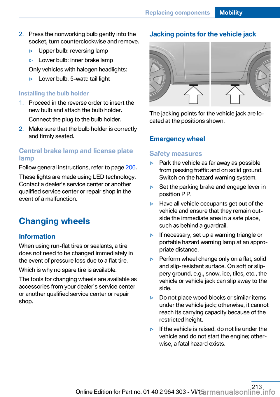
Jacking points for the vehicle jack
The jacking points for the vehicle jack are lo‐
cated at the positions shown.
Emergency wheel
Safety measures
▷Park the vehicle as far away as possible
from passing traffic and on solid ground.
Switch on the hazard warning system.▷Set the parking brake and engage lever in
position P P.▷Have all vehicle occupants get out of the
vehicle and ensure that they remain out‐
side the immediate area in a safe place,
such as behind a guardrail.▷If necessary, set up a warning triangle or
portable hazard warning lamp at an appro‐
priate distance.▷Perform wheel change only on a flat, solid
and slip-resistant surface. On soft or slip‐
pery ground, e.g., snow, ice, tiles, etc., the
vehicle or vehicle jack can slip away to the
side.▷Do not place wood blocks or similar items
under the vehicle jack; otherwise, it cannot
reach its carrying capacity because of the
restricted height.▷If the vehicle is raised, do not lie under the
vehicle and do not start the engine; other‐
wise, a fatal hazard exists.Seite 213Replacing componentsMobility213
Online Edition for Part no. 01 40 2 964 303 - VI/15
Page 214 of 242
InformationWARNING
The vehicle jack is optimized for lifting
the vehicle and for the jacking points on the
vehicle only. There is risk of injuries. Do not lift
any other vehicle or cargo using the vehicle
jack.◀
Removing the emergency wheel The emergency wheel and the tools are lo‐
cated in the trunk under the cargo floor panel.1.Unscrew the wing nut.2.Remove the cover.3.Remove tool holder.4.Remove emergency wheel.
Prepare wheel change
1.Follow the Safety instructions, refer to
page 214.2.With the wheel chock from the onboard ve‐
hicle tool kit, also secure the vehicle
against rolling away at the front wheel of
the opposite side. For this, place the wheel
chock behind the front wheel diagonally
across.3.Loosen the wheel lug bolts a half turn.
Jacking up the vehicle
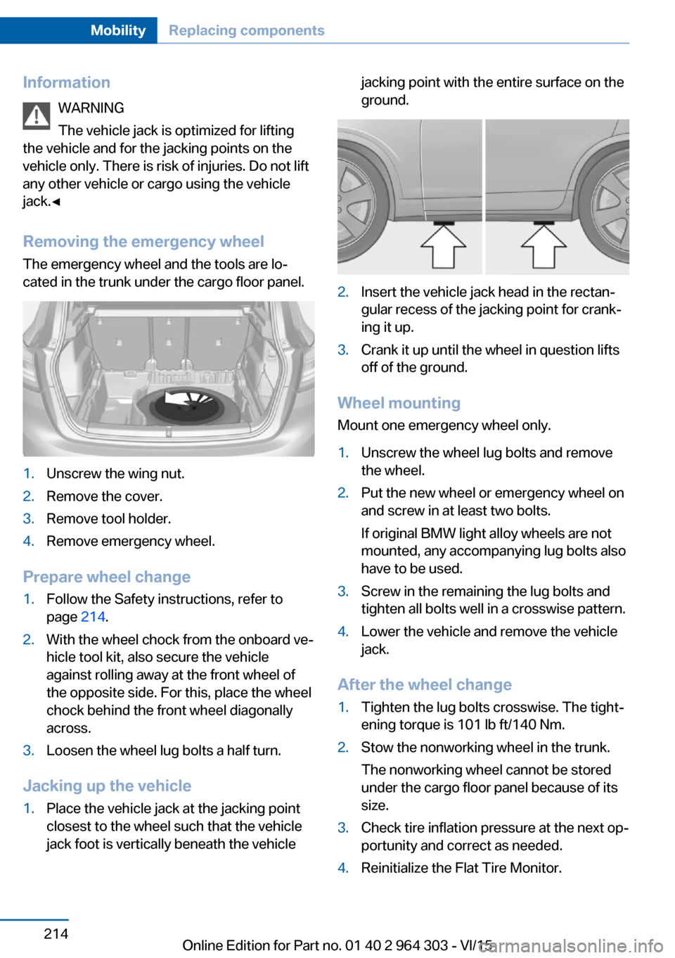
1.Place the vehicle jack at the jacking point
closest to the wheel such that the vehicle
jack foot is vertically beneath the vehiclejacking point with the entire surface on the
ground.2.Insert the vehicle jack head in the rectan‐
gular recess of the jacking point for crank‐
ing it up.3.Crank it up until the wheel in question lifts
off of the ground.
Wheel mounting
Mount one emergency wheel only.
1.Unscrew the wheel lug bolts and remove
the wheel.2.Put the new wheel or emergency wheel on
and screw in at least two bolts.
If original BMW light alloy wheels are not
mounted, any accompanying lug bolts also
have to be used.3.Screw in the remaining the lug bolts and
tighten all bolts well in a crosswise pattern.4.Lower the vehicle and remove the vehicle
jack.
After the wheel change
1.Tighten the lug bolts crosswise. The tight‐
ening torque is 101 lb ft/140 Nm.2.Stow the nonworking wheel in the trunk.
The nonworking wheel cannot be stored
under the cargo floor panel because of its
size.3.Check tire inflation pressure at the next op‐
portunity and correct as needed.4.Reinitialize the Flat Tire Monitor.Seite 214MobilityReplacing components214
Online Edition for Part no. 01 40 2 964 303 - VI/15
Page 236 of 242
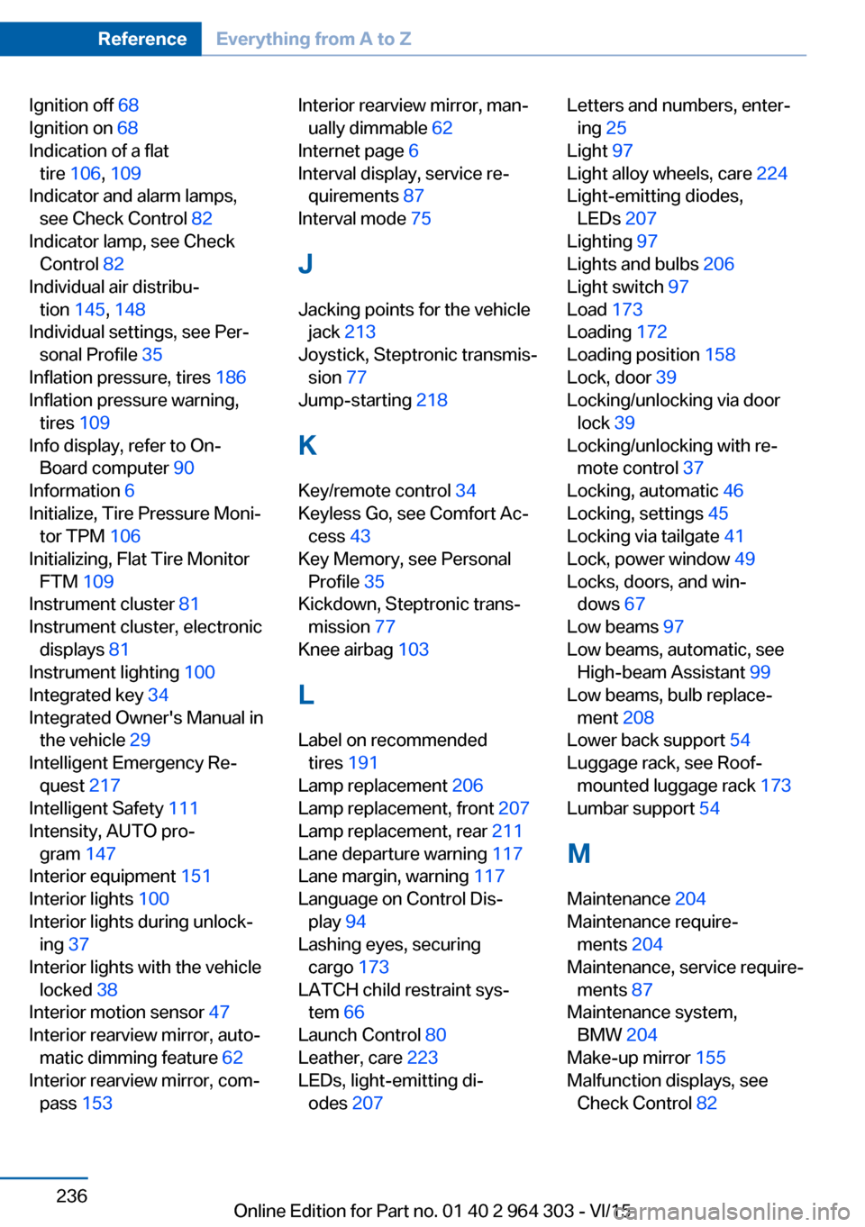
Ignition off 68
Ignition on 68
Indication of a flat tire 106 , 109
Indicator and alarm lamps, see Check Control 82
Indicator lamp, see Check Control 82
Individual air distribu‐ tion 145, 148
Individual settings, see Per‐ sonal Profile 35
Inflation pressure, tires 186
Inflation pressure warning, tires 109
Info display, refer to On- Board computer 90
Information 6
Initialize, Tire Pressure Moni‐ tor TPM 106
Initializing, Flat Tire Monitor FTM 109
Instrument cluster 81
Instrument cluster, electronic displays 81
Instrument lighting 100
Integrated key 34
Integrated Owner's Manual in the vehicle 29
Intelligent Emergency Re‐ quest 217
Intelligent Safety 111
Intensity, AUTO pro‐ gram 147
Interior equipment 151
Interior lights 100
Interior lights during unlock‐ ing 37
Interior lights with the vehicle locked 38
Interior motion sensor 47
Interior rearview mirror, auto‐ matic dimming feature 62
Interior rearview mirror, com‐ pass 153 Interior rearview mirror, man‐
ually dimmable 62
Internet page 6
Interval display, service re‐ quirements 87
Interval mode 75
J Jacking points for the vehicle jack 213
Joystick, Steptronic transmis‐ sion 77
Jump-starting 218
K
Key/remote control 34
Keyless Go, see Comfort Ac‐ cess 43
Key Memory, see Personal Profile 35
Kickdown, Steptronic trans‐ mission 77
Knee airbag 103
L Label on recommended tires 191
Lamp replacement 206
Lamp replacement, front 207
Lamp replacement, rear 211
Lane departure warning 117
Lane margin, warning 117
Language on Control Dis‐ play 94
Lashing eyes, securing cargo 173
LATCH child restraint sys‐ tem 66
Launch Control 80
Leather, care 223
LEDs, light-emitting di‐ odes 207 Letters and numbers, enter‐
ing 25
Light 97
Light alloy wheels, care 224
Light-emitting diodes, LEDs 207
Lighting 97
Lights and bulbs 206
Light switch 97
Load 173
Loading 172
Loading position 158
Lock, door 39
Locking/unlocking via door lock 39
Locking/unlocking with re‐ mote control 37
Locking, automatic 46
Locking, settings 45
Locking via tailgate 41
Lock, power window 49
Locks, doors, and win‐ dows 67
Low beams 97
Low beams, automatic, see High-beam Assistant 99
Low beams, bulb replace‐ ment 208
Lower back support 54
Luggage rack, see Roof- mounted luggage rack 173
Lumbar support 54
M
Maintenance 204
Maintenance require‐ ments 204
Maintenance, service require‐ ments 87
Maintenance system, BMW 204
Make-up mirror 155
Malfunction displays, see Check Control 82 Seite 236ReferenceEverything from A to Z236
Online Edition for Part no. 01 40 2 964 303 - VI/15
Page 240 of 242
Triple turn signal activa‐tion 73
Trip odometer 86
Trip on-board computer 92
Trip recorder, see Trip odom‐ eter 86
Turning circle lines, rearview camera 139
Turn signal, bulb replace‐ ment 208, 209
Turn signals, operation 73
Turn signals, rear, bulb re‐ placement 211
U
Unintentional alarm 47
Units of measurement 94
Universal remote control 151
Unlock button, Steptronic transmission 78
Unlocking/locking via door lock 39
Unlocking/locking with re‐ mote control 37
Unlocking, settings 45
Unpaved roads, cross-coun‐ try trips 168
Updates made after the edito‐ rial deadline 7
Upholstery care 223
USB interface 156
V
Vanity mirror 155
Variable sport steering 123
Vehicle battery 215
Vehicle battery, replac‐ ing 215
Vehicle, break-in 168
Vehicle care 223
Vehicle features and op‐ tions 7
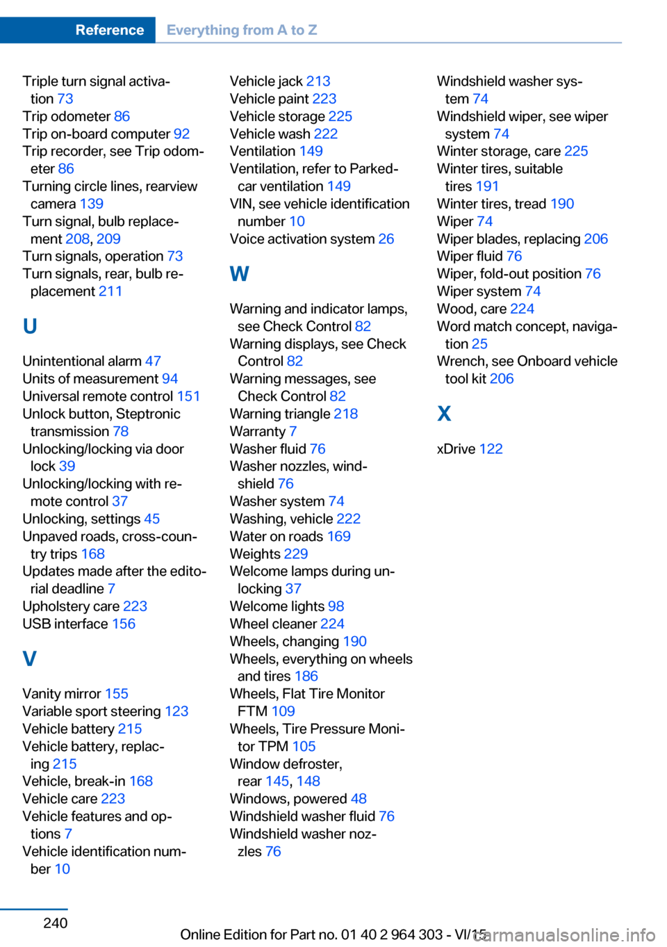
Vehicle identification num‐ ber 10 Vehicle jack 213
Vehicle paint 223
Vehicle storage 225
Vehicle wash 222
Ventilation 149
Ventilation, refer to Parked- car ventilation 149
VIN, see vehicle identification number 10
Voice activation system 26
W Warning and indicator lamps, see Check Control 82
Warning displays, see Check Control 82
Warning messages, see Check Control 82
Warning triangle 218
Warranty 7
Washer fluid 76
Washer nozzles, wind‐ shield 76
Washer system 74
Washing, vehicle 222
Water on roads 169
Weights 229
Welcome lamps during un‐ locking 37
Welcome lights 98
Wheel cleaner 224
Wheels, changing 190
Wheels, everything on wheels and tires 186
Wheels, Flat Tire Monitor FTM 109
Wheels, Tire Pressure Moni‐ tor TPM 105
Window defroster, rear 145, 148
Windows, powered 48
Windshield washer fluid 76
Windshield washer noz‐ zles 76 Windshield washer sys‐
tem 74
Windshield wiper, see wiper system 74
Winter storage, care 225
Winter tires, suitable tires 191
Winter tires, tread 190
Wiper 74
Wiper blades, replacing 206
Wiper fluid 76
Wiper, fold-out position 76
Wiper system 74
Wood, care 224
Word match concept, naviga‐ tion 25
Wrench, see Onboard vehicle tool kit 206
X
xDrive 122 Seite 240ReferenceEverything from A to Z240
Online Edition for Part no. 01 40 2 964 303 - VI/15