tow BMW X3 2.5I 2005 E83 User Guide
[x] Cancel search | Manufacturer: BMW, Model Year: 2005, Model line: X3 2.5I, Model: BMW X3 2.5I 2005 E83Pages: 126, PDF Size: 4.65 MB
Page 60 of 126
Reference
At a glance
Controls
Driving tips
Mobility
59
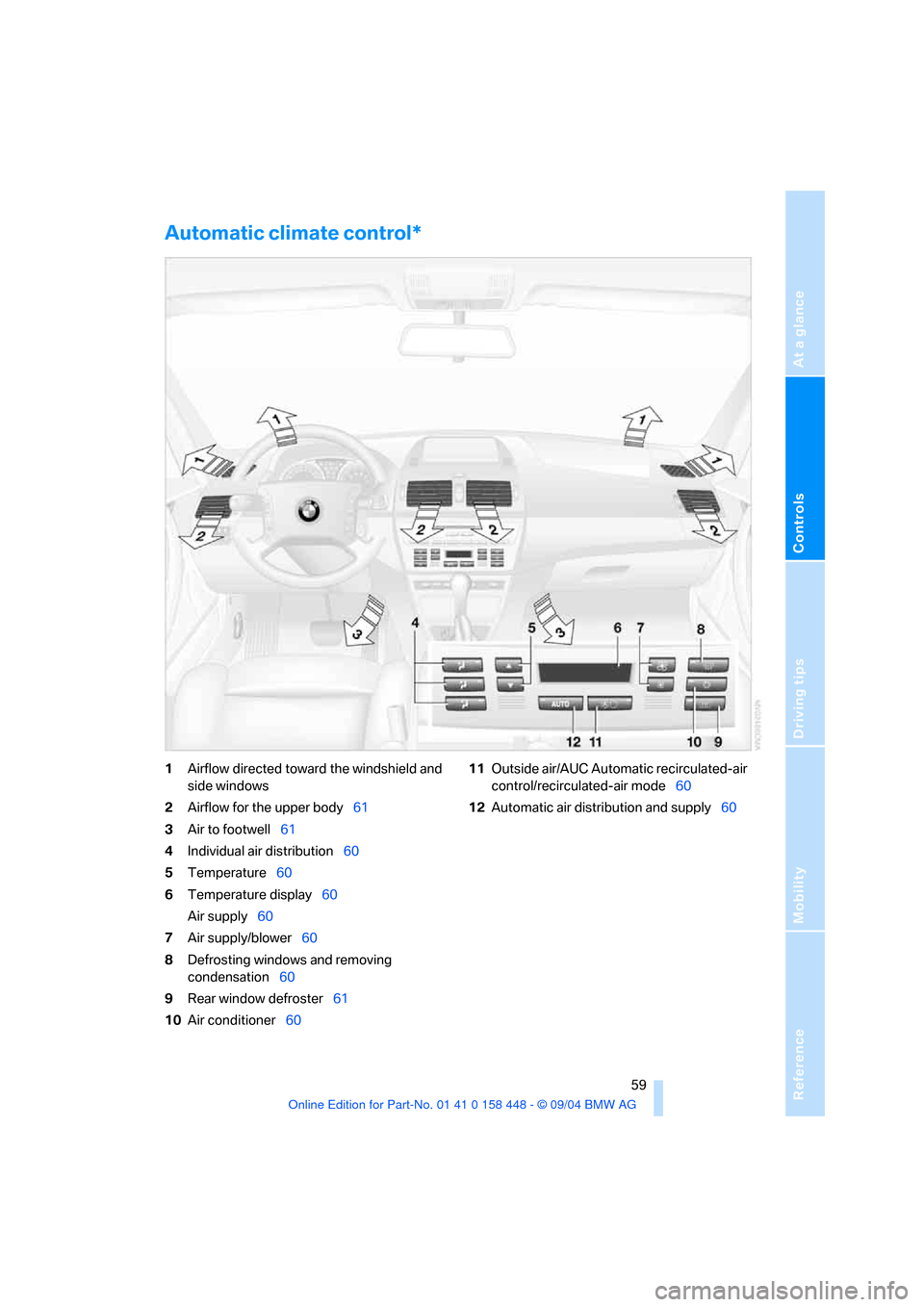
Automatic climate control*
1Airflow directed toward the windshield and
side windows
2Airflow for the upper body61
3Air to footwell61
4Individual air distribution60
5Temperature60
6Temperature display60
Air supply60
7Air supply/blower60
8Defrosting windows and removing
condensation60
9Rear window defroster61
10Air conditioner6011Outside air/AUC Automatic recirculated-air
control/recirculated-air mode60
12Automatic air distribution and supply60
Page 61 of 126
A congenial climate
60
A congenial climate
For almost all conditions, the AUTO pro-
gram 12 offers the optimal air distribution and
air volume. Select an interior temperature you
find pleasant.
The following section contains more detailed
information on the available setting options.
Your vehicle has been designed to auto-
matically select your personal climate-
control settings whenever you unlock the doors
using your individually programmed remote
control.<
Automatic air distribution and supply
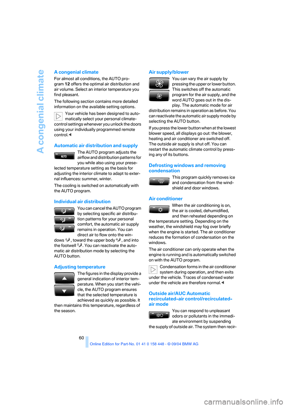
The AUTO program adjusts the
airflow and distribution patterns for
you while also using your prese-
lected temperature setting as the basis for
adjusting the interior climate to adapt to exter-
nal influences: summer, winter.
The cooling is switched on automatically with
the AUTO program.
Individual air distribution
You can cancel the AUTO program
by selecting specific air distribu-
tion patterns for your personal
comfort, the automatic air supply
remains in operation. You can
direct air to flow onto the win-
dows , toward the upper body , and into
the footwell . You can reactivate the auto-
matic air distribution mode by selecting the
AUTO button.
Adjusting temperature
The figures in the display provide a
general indication of interior tem-
perature. When you start the vehi-
cle, the AUTO program ensures
that the selected temperature is
achieved as quickly as possible. It
then maintains this temperature, regardless of
the season.
Air supply/blower
You can vary the air supply by
pressing the upper or lower button.
This switches off the automatic
program for the air supply, and the
word AUTO goes out in the dis-
play. The automatic mode for air
distribution remains in operation as before. You
can reactivate the automatic air supply mode by
selecting the AUTO button.
If you press the lower button when at the lowest
blower speed, all displays go out: the blower,
heating and air conditioner are switched off.
The outside air supply is shut off. You can
restart the automatic climate control by press-
ing any of its buttons.
Defrosting windows and removing
condensation
This program quickly removes ice
and condensation from the wind-
shield and door windows.
Air conditioner
When the air conditioning is on,
the air is cooled, dehumidified,
and then reheated depending on
the temperature setting. Depending on the
weather, the windshield may fog over briefly
when the engine is started. The air conditioner
reduces the formation of condensation on the
windows.
The air conditioner can only operate when the
engine is running and is automatically switched
on with the AUTO program.
Condensation forms in the air conditioner
system during operation, and then exits
under the vehicle. Traces of condensed water
under the vehicle are therefore normal.<
Outside air/AUC Automatic
recirculated-air control/recirculated-
air mode
You can respond to unpleasant
odors or pollutants in the immedi-
ate environment by suspending
the supply of outside air. The system then recir-
Page 67 of 126
Practical interior accessories
66
Car phone preparation*
Hands-free system
In vehicles with car phone preparation*, the
hands-free microphone is located on the head-
liner near the interior lamp.
For more information on the car phone, refer to
the Owner's Manual for Telephone.
Ski bag*
The ski bag allows the safe and clean transport
of up to 4 pairs of standard skis or up to two
snowboards.
The ski bag itself plus the additional capacity
provided by the cargo area make it possible to
transport skis with a length of up to 6.9 ft/
2.10 m. When skis of 6.9 ft/2.10 m in length are
loaded the ski bag will tend to narrow, reducing
its overall capacity.
Loading
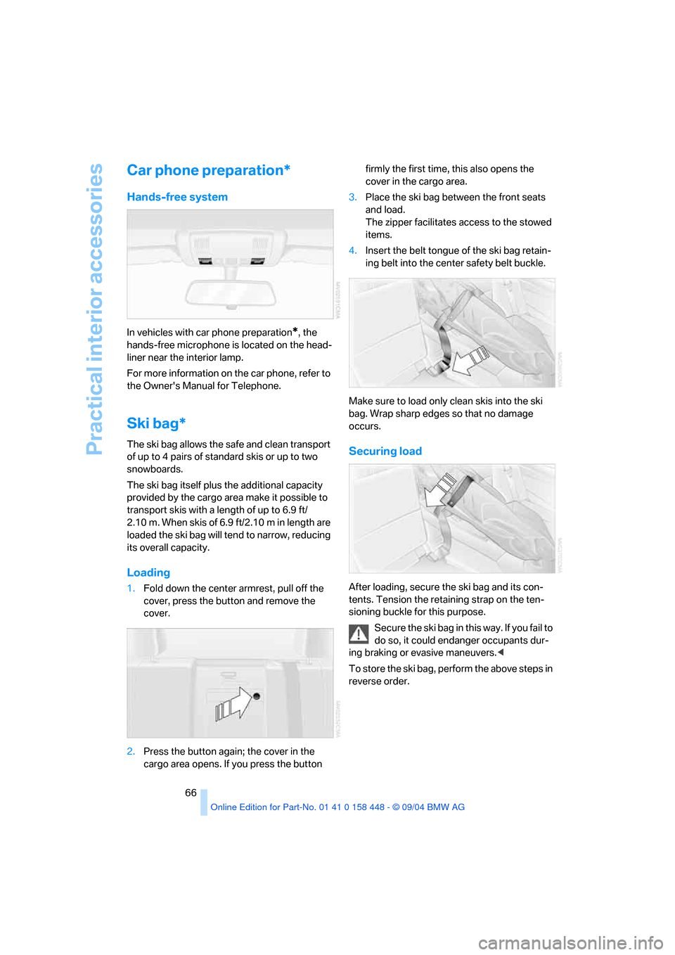
1.Fold down the center armrest, pull off the
cover, press the button and remove the
cover.
2.Press the button again; the cover in the
cargo area opens. If you press the button firmly the first time, this also opens the
cover in the cargo area.
3.Place the ski bag between the front seats
and load.
The zipper facilitates access to the stowed
items.
4.Insert the belt tongue of the ski bag retain-
ing belt into the center safety belt buckle.
Make sure to load only clean skis into the ski
bag. Wrap sharp edges so that no damage
occurs.
Securing load
After loading, secure the ski bag and its con-
tents. Tension the retaining strap on the ten-
sioning buckle for this purpose.
Secure the ski bag in this way. If you fail to
do so, it could endanger occupants dur-
ing braking or evasive maneuvers.<
To store the ski bag, perform the above steps in
reverse order.
Page 69 of 126
Practical interior accessories
68 Do not place heavy and hard objects on
the cover. If you do so, they could endan-
ger occupants during braking maneuvers. Do
not allow the cover to snap back into place, as
otherwise it could be damaged.<
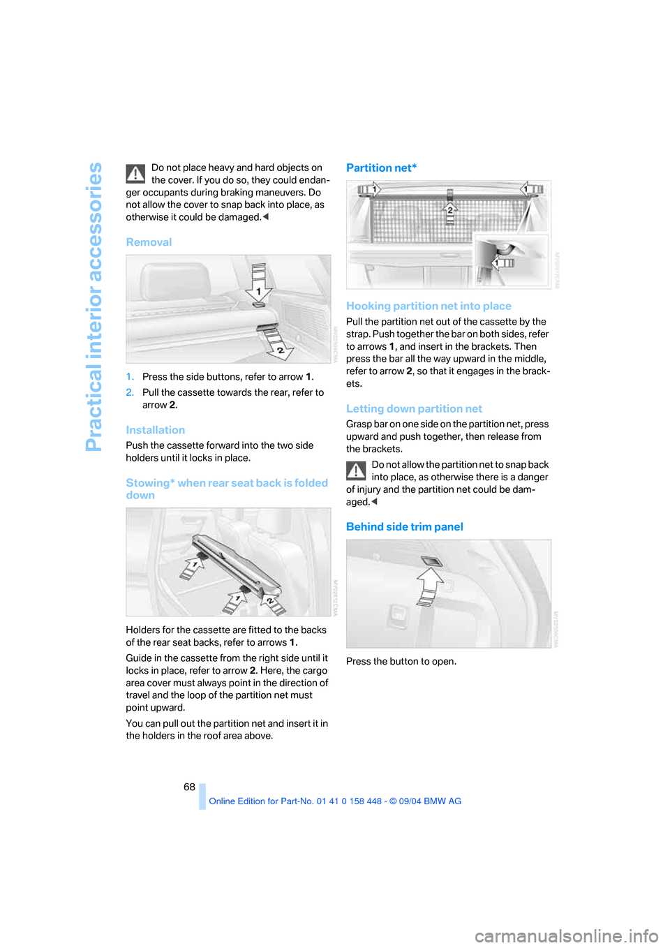
Removal
1.Press the side buttons, refer to arrow1.
2.Pull the cassette towards the rear, refer to
arrow2.
Installation
Push the cassette forward into the two side
holders until it locks in place.
Stowing* when rear seat back is folded
down
Holders for the cassette are fitted to the backs
of the rear seat backs, refer to arrows1.
Guide in the cassette from the right side until it
locks in place, refer to arrow 2. Here, the cargo
area cover must always point in the direction of
travel and the loop of the partition net must
point upward.
You can pull out the partition net and insert it in
the holders in the roof area above.
Partition net*
Hooking partition net into place
Pull the partition net out of the cassette by the
strap. Push together the bar on both sides, refer
to arrows 1, and insert in the brackets. Then
press the bar all the way upward in the middle,
refer to arrow 2, so that it engages in the brack-
ets.
Letting down partition net
Grasp bar on one side on the partition net, press
upward and push together, then release from
the brackets.
Do not allow the partition net to snap back
into place, as otherwise there is a danger
of injury and the partition net could be dam-
aged.<
Behind side trim panel
Press the button to open.
Page 73 of 126
Things to remember when driving
72
Things to remember when driving
Breaking-in
Moving parts should be allowed to adjust to one
another. To ensure that your vehicle provides
maximum economy throughout a long service
life, we request that you observe the following
instructions.
Engine and differential
Up to 1,200 miles/2,000 km:
Drive at varying engine and driving speeds,
however do not exceed 4,500 rpm or 100 mph/
160 km/h in the process:
Always obey all official speed limits.
Refrain from using full throttle and avoid press-
ing the accelerator beyond the kick-down point.
Once you have driven 1,200 miles/2,000 km,
the engine and vehicle speeds can be gradually
increased.
Tires
Due to technical factors associated with their
manufacture, tires do not achieve their full trac-
tion potential until after an initial break-in
period. For this reason, drive with extra care
during the initial 200 miles/300 km.
Obey your local and state maximum speed lim-
its.
When the vehicle is operated on wet or
slushy roads, a wedge of water may form
between the tire and the road surface. This phe-
nomenon is referred to as hydroplaning and can
lead to partial or complete loss of traction, vehi-
cle control and braking effectiveness. Reduce
your speed on wet roads.<
Brake system
Approx. 300 miles/500 km must elapse before
the brake pads and rotors achieve the optimal
pad-surface and wear patterns required for
trouble-free operation and long service life later
on. To break in the separate handbrake drums,
apply the handbrake lightly when coasting to a
stop – at a traffic signal, for instance; use cau-
tion to avoid posing a danger to other road
users.
To avoid corrosion, repeat this procedure from
time to time.
The brake lamps do not come on when the
handbrake is applied.
Vacuum for the brake system servo unit
on your BMW is available only when the
engine is running. When you move the vehicle
with the engine off – e.g. by towing – substan-
tially higher levels of pedal force will be required
to brake the vehicle.<
Clutch
The functio n of the clutch is als o only at its o pti-
mized level after a distance driven of approx.
300 miles/500 km. During this break-in period,
engage the clutch gently.
Following component replacements
Observe the break-in instructions again if previ-
ously addressed components must be replaced
again during driving later.
General driving notes
Closing tailgate
Operate the vehicle only when the tail-
gate is completely closed, as otherwise
exhaust fumes could enter the interior of the
vehicle.<
If special circumstances should make it abso-
lutely necessary to operate the vehicle with the
tailgate open:
1.Close all windows and the panorama glass
sunroof.
2.Greatly increase the air supply of the air
conditioner or automatic climate control,
refer to page56 or59.
Page 76 of 126
Reference
At a glance
Controls
Driving tips
Mobility
75
3.Subtract the combined weight of the driver
and passengers from XXX lbs. or YYY kg.
4.The resulting figure equals the available
amount of cargo and luggage load capacity.
For example, if the XXX amount equals
990 lbs. and there will be five 150-lbs. pas-
sengers in your vehicle, the amount of avail-
able cargo and luggage load capacity is
240 lbs.:
990 lbs. minus 750 lbs. = 240 lbs.
5.Determine the combined weight of luggage
and cargo being loaded on the vehicle. That
weight may not safely exceed the available
cargo and luggage load capacity calculated
in step 4.
6.If your vehicle will be towing a trailer, part of
the load from your trailer will be transferred
to your vehicle. Consult the manual for
transporting a trailer to determine how this
may reduce the available cargo and luggage
load capacity of your vehicle.
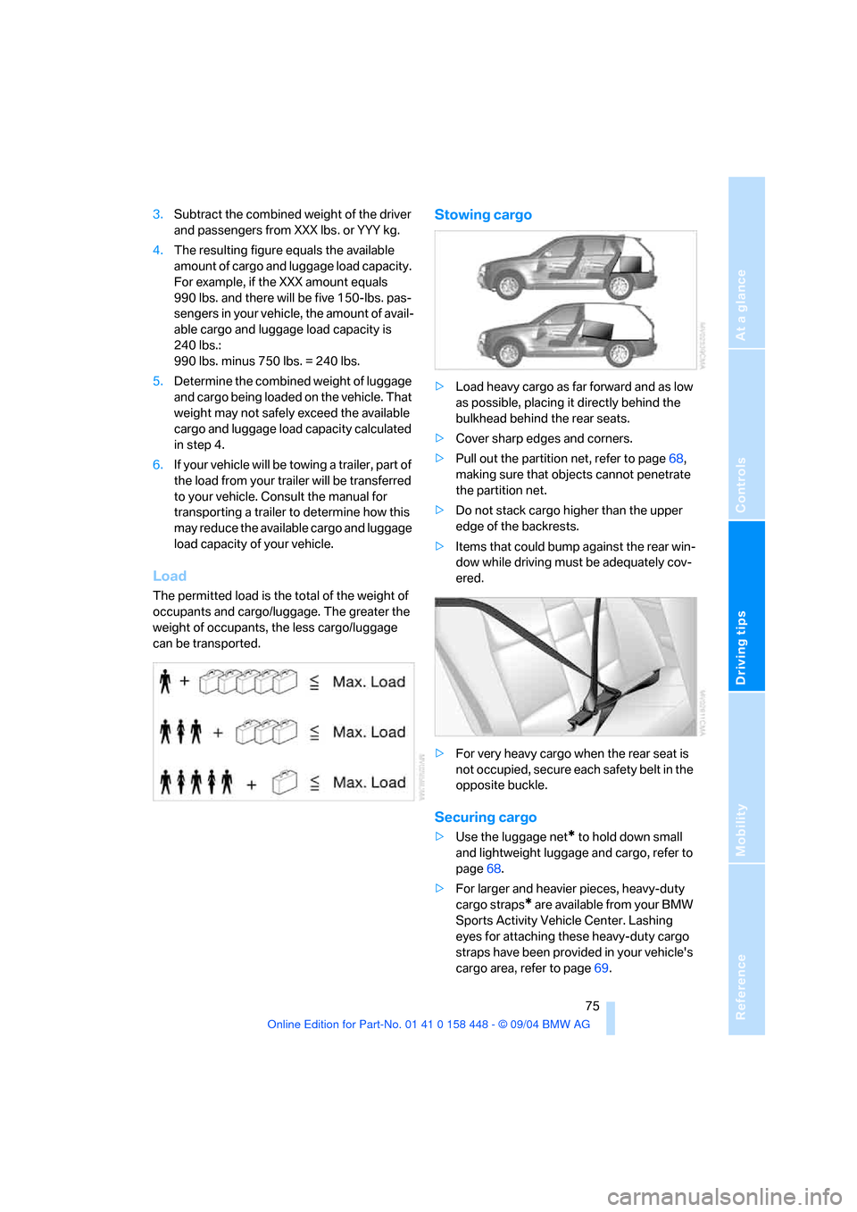
Load
The permitted load is the total of the weight of
occupants and cargo/luggage. The greater the
weight of occupants, the less cargo/luggage
can be transported.
Stowing cargo
>Load heavy cargo as far forward and as low
as possible, placing it directly behind the
bulkhead behind the rear seats.
>Cover sharp edges and corners.
>Pull out the partition net, refer to page68,
making sure that objects cannot penetrate
the partition net.
>Do not stack cargo higher than the upper
edge of the backrests.
>Items that could bump against the rear win-
dow while driving must be adequately cov-
ered.
>For very heavy cargo when the rear seat is
not occupied, secure each safety belt in the
opposite buckle.
Securing cargo
>Use the luggage net* to hold down small
and lightweight luggage and cargo, refer to
page68.
>For larger and heavier pieces, heavy-duty
cargo straps
* are available from your BMW
Sports Activity Vehicle Center. Lashing
eyes for attaching these heavy-duty cargo
straps have been provided in your vehicle's
cargo area, refer to page69.
Page 86 of 126
Reference
At a glance
Controls
Driving tips
Mobility
85
Temperature
The temperature grades are A, the highest, B
and C, representing the tire's resistance to the
generation of heat and its ability to dissipate
heat when tested under controlled conditions
on a specified indoor laboratory test wheel.
Sustained high temperature can cause the
material of the tire to degenerate and reduce
tire life, and excessive temperature can lead to
sudden tire failure. The grade C corresponds to
a level of performance which all passenger car
tires must meet under the Federal Motor Vehi-
cle Safety Standard No. 109. Grades B and A
represent higher levels of performance on the
laboratory test wheel than the minimum
required by law.
The temperature grade for this tire is
established for a tire that is properly
inflated and not overloaded. Excessive speed,
underinflation, or excessive loading, either sep-
arately or in combination, can cause heat
buildup and possible tire failure.<
M+S
Winter and all-season tires.
These have better winter properties than sum-
mer tires.
Tire condition
Inspect your tires frequently for tread wear,
signs of damage and for foreign objects lodged
in the tread. Check the tread pattern depth.
Tire tread
The tread depth should not drop below 0.12 in/
3 mm, although, for example, European legisla-
tion only specifies a minimum tread depth of
0.063 in/1.6 mm.
At tread depths below 0.12 in/3 mm, there is an
increased risk of high-speed hydroplaning,
even when only small amounts of water are
present on the road surface. As winter tires dis-
play a noticeable loss in their ability to cope with
cold-weather driving conditions once the tread
wears to below 0.16 in/4 mm, to ensure contin-ued safety you should always have such tires
replaced.
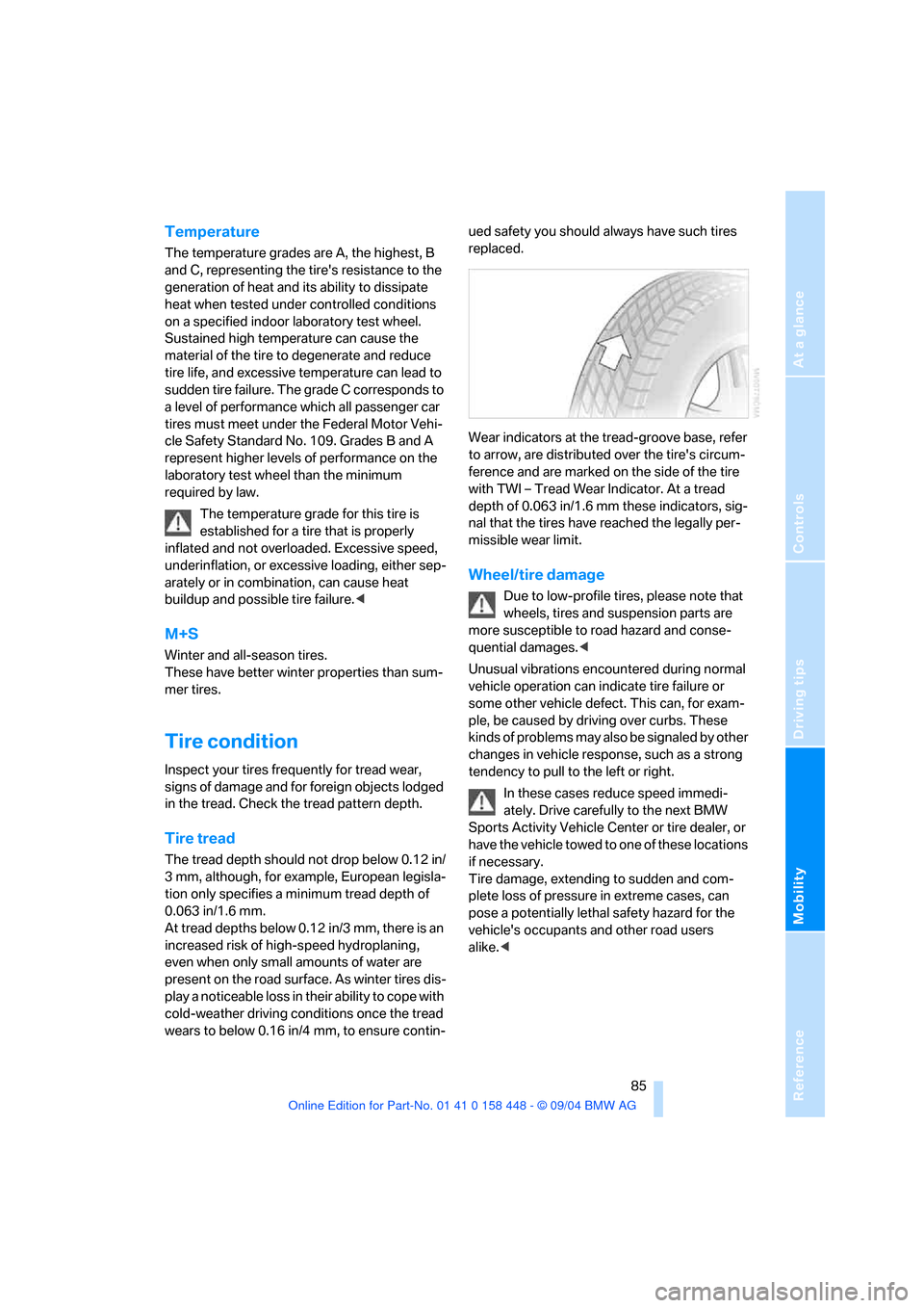
Wear indicators at the tread-groove base, refer
to arrow, are distributed over the tire's circum-
ference and are marked on the side of the tire
with TWI – Tread Wear Indicator. At a tread
depth of 0.063 in/1.6 mm these indicators, sig-
nal that the tires have reached the legally per-
missible wear limit.
Wheel/tire damage
Due to low-profile tires, please note that
wheels, tires and suspension parts are
more susceptible to road hazard and conse-
quential damages.<
Unusual vibrations encountered during normal
vehicle operation can indicate tire failure or
some other vehicle defect. This can, for exam-
ple, be caused by driving over curbs. These
kinds of problems may also be signaled by other
changes in vehicle response, such as a strong
tendency to pull to the left or right.
In these cases reduce speed immedi-
ately. Drive carefully to the next BMW
Sports Activity Vehicle Center or tire dealer, or
have the vehicle towed to one of these locations
if necessary.
Tire damage, extending to sudden and com-
plete loss of pressure in extreme cases, can
pose a potentially lethal safety hazard for the
vehicle's occupants and other road users
alike.<
Page 91 of 126
Under the hood
90
Washer fluid
Headlamp* and windshield washer
system
The antifreeze for the washer systems is
flammable. For this reason, keep it away
from sources of flame and store it only in its
original containers. Store it so that it is inacces-
sible to children. Always observe the instruc-
tions for use provided on the containers.<
We recommend that you mix the washer
fluid before adding it to the reservoir.<
Capacity of the windshield washer system:
approx. 3.2 US quarts/3 liters.
Capacity for equipment with headlamp washer
system: approx. 6.9 US quarts/6.5 liters.
Fill with water and, if required, with an antifreeze
additive according to manufacturer's recom-
mendations.
Engine oil
Engine oil consumption depends on driving
style and operating conditions.
Warning lamp
Engine oil pressure
The warning lamp lights up red:
Stop the vehicle immediately and
switch off the engine. Check the engine
oil level; top off as required. If the oil level is cor-
rect: have the system checked immediately.
Do not continue driving. The engine could
be damaged because of inadequate lubri-
cation.<
Engine oil level
The warning lamp lights up yellow while
driving:
The oil level is at the absolute mini-
mum. Add engine oil as soon as possible. Until
then, do not drive more than approx. 30 miles/
50 km.
The warning lamp lights up yellow after
the engine is switched off:
Top off engine oil at the earliest oppor-
tunity, e.g. when refueling.
Engine oil sensor
The warning lamp lights up yellow
within 20 seconds after starting the
engine:
The oil level sensor is defective. Have checked
as soon as possible.
Checking oil level
1.With the engine at operating temperature,
i.e. after at least 6 miles/10 km of uninter-
rupted driving, park the vehicle in a horizon-
tal position.
2.Switch off engine.
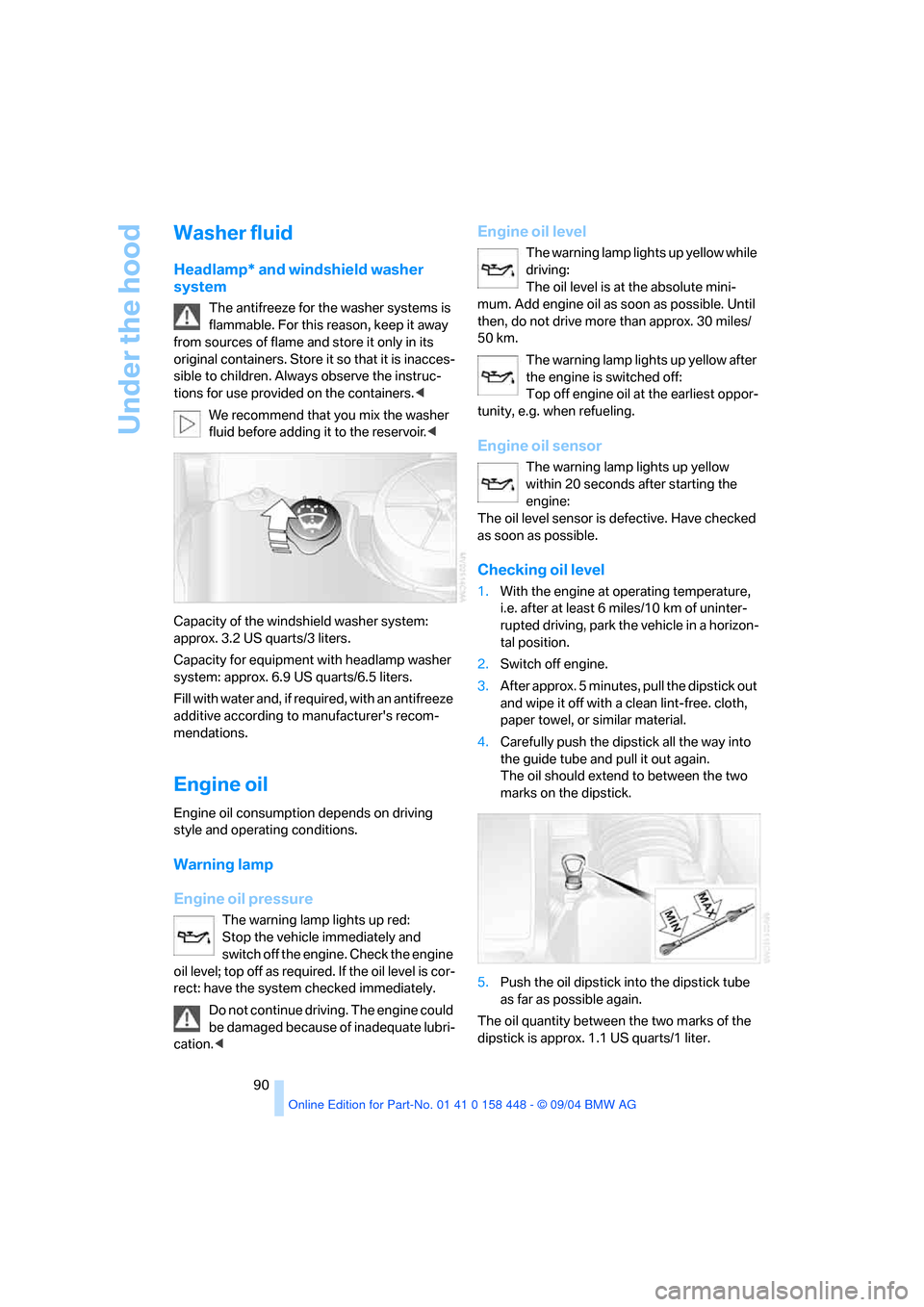
3.After approx. 5 minutes, pull the dipstick out
and wipe it off with a clean lint-free. cloth,
paper towel, or similar material.
4.Carefully push the dipstick all the way into
the guide tube and pull it out again.
The oil should extend to between the two
marks on the dipstick.
5.Push the oil dipstick into the dipstick tube
as far as possible again.
The oil quantity between the two marks of the
dipstick is approx. 1.1 US quarts/1 liter.
Page 96 of 126
Reference
At a glance
Controls
Driving tips
Mobility
95
Replacing components
Onboard tool kit
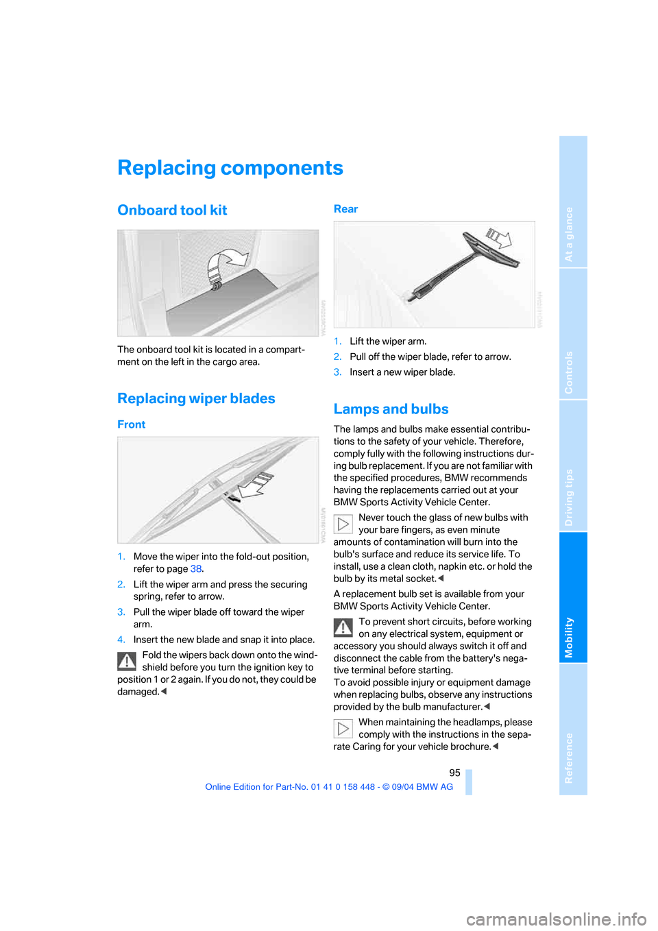
The onboard tool kit is located in a compart-
ment on the left in the cargo area.
Replacing wiper blades
Front
1.Move the wiper into the fold-out position,
refer to page38.
2.Lift the wiper arm and press the securing
spring, refer to arrow.
3.Pull the wiper blade off toward the wiper
arm.
4.Insert the new blade and snap it into place.
Fold the wipers back down onto the wind-
shield before you turn the ignition key to
p o s i t i o n 1 o r 2 a g a i n . I f y o u d o n o t , t h e y c o u l d b e
damaged.<
Rear
1.Lift the wiper arm.
2.Pull off the wiper blade, refer to arrow.
3.Insert a new wiper blade.
Lamps and bulbs
The lamps and bulbs make essential contribu-
tions to the safety of your vehicle. Therefore,
comply fully with the following instructions dur-
ing bulb replacement. If you are not familiar with
the specified procedures, BMW recommends
having the replacements carried out at your
BMW Sports Activity Vehicle Center.
Never touch the glass of new bulbs with
your bare fingers, as even minute
amounts of contamination will burn into the
bulb's surface and reduce its service life. To
install, use a clean cloth, napkin etc. or hold the
bulb by its metal socket.<
A replacement bulb set is available from your
BMW Sports Activity Vehicle Center.
To prevent short circuits, before working
on any electrical system, equipment or
accessory you should always switch it off and
disconnect the cable from the battery's nega-
tive terminal before starting.
To avoid possible injury or equipment damage
when replacing bulbs, observe any instructions
provided by the bulb manufacturer.<
When maintaining the headlamps, please
comply with the instructions in the sepa-
rate Caring for your vehicle brochure.<
Page 101 of 126
Replacing components
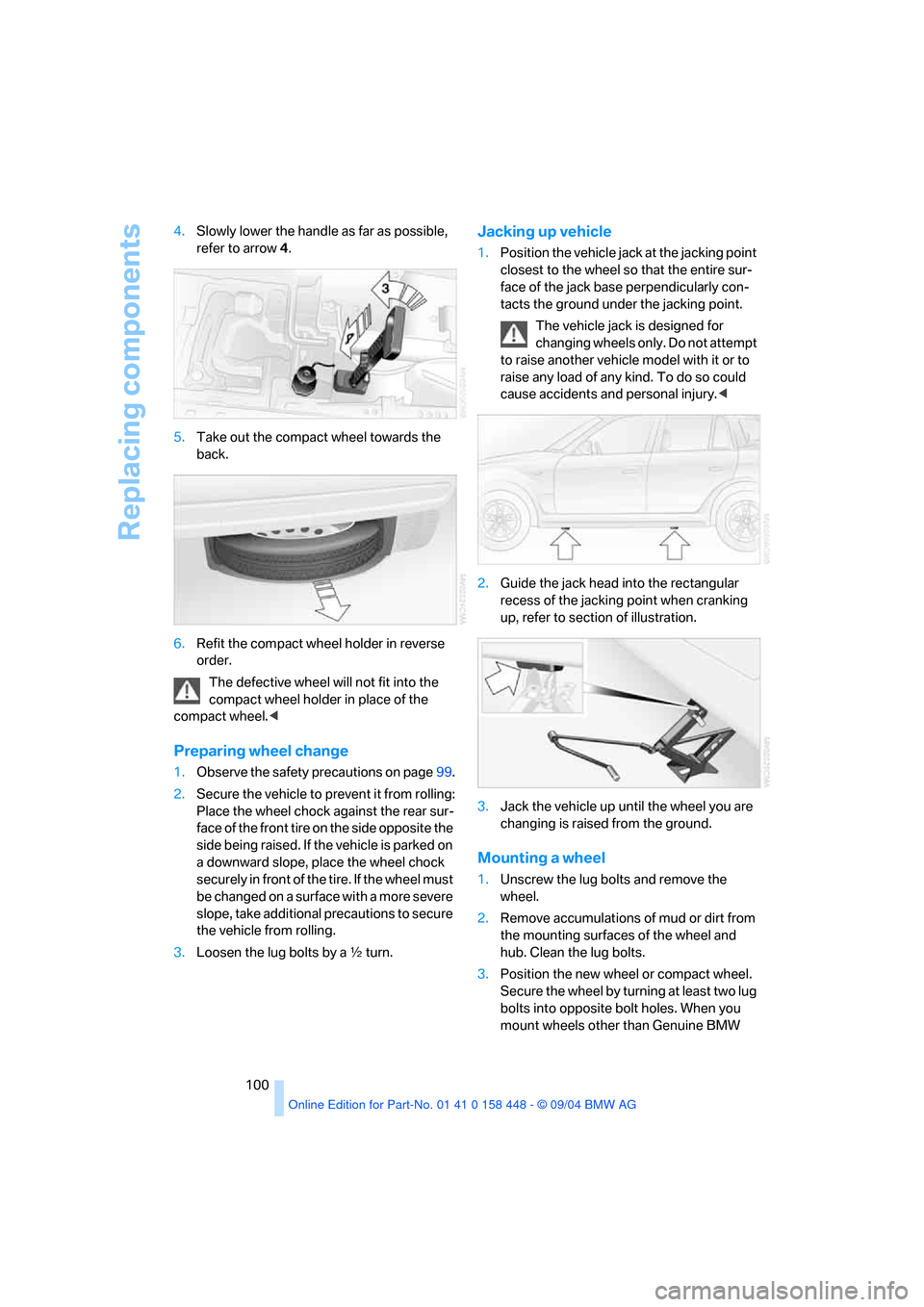
100 4.Slowly lower the handle as far as possible,
refer to arrow4.
5.Take out the compact wheel towards the
back.
6.Refit the compact wheel holder in reverse
order.
The defective wheel will not fit into the
compact wheel holder in place of the
compact wheel.<
Preparing wheel change
1.Observe the safety precautions on page99.
2.Secure the vehicle to prevent it from rolling:
Place the wheel chock against the rear sur-
face of the front tire on the side opposite the
side being raised. If the vehicle is parked on
a downward slope, place the wheel chock
securely in front of the tire. If the wheel must
be changed on a surface with a more severe
slope, take additional precautions to secure
the vehicle from rolling.
3.Loosen the lug bolts by a γ turn.
Jacking up vehicle
1.Position the vehicle jack at the jacking point
closest to the wheel so that the entire sur-
face of the jack base perpendicularly con-
tacts the ground under the jacking point.
The vehicle jack is designed for
changing wheels only. Do not attempt
to raise another vehicle model with it or to
raise any load of any kind. To do so could
cause accidents and personal injury.<
2.Guide the jack head into the rectangular
recess of the jacking point when cranking
up, refer to section of illustration.
3.Jack the vehicle up until the wheel you are
changing is raised from the ground.
Mounting a wheel
1.Unscrew the lug bolts and remove the
wheel.
2.Remove accumulations of mud or dirt from
the mounting surfaces of the wheel and
hub. Clean the lug bolts.
3.Position the new wheel or compact wheel.
Secure the wheel by turning at least two lug
bolts into opposite bolt holes. When you
mount wheels other than Genuine BMW