BMW X3 2013 F25 Manual Online
Manufacturer: BMW, Model Year: 2013, Model line: X3, Model: BMW X3 2013 F25Pages: 212, PDF Size: 4.8 MB
Page 81 of 212
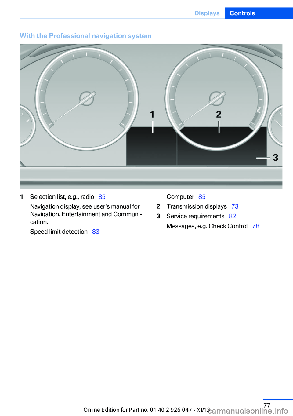
With the Professional navigation system1Selection list, e.g., radioŌĆéŌĆģ85
Navigation display, see user's manual for
Navigation, Entertainment and CommuniŌĆÉ
cation.
Speed limit detectionŌĆéŌĆģ 83ComputerŌĆéŌĆģ852Transmission displaysŌĆéŌĆģ 733Service requirementsŌĆéŌĆģ82
Messages, e.g. Check ControlŌĆéŌĆģ 78Seite 77DisplaysControls77
Online Edition for Part no. 01 40 2 911 041 - VI/13
Page 82 of 212
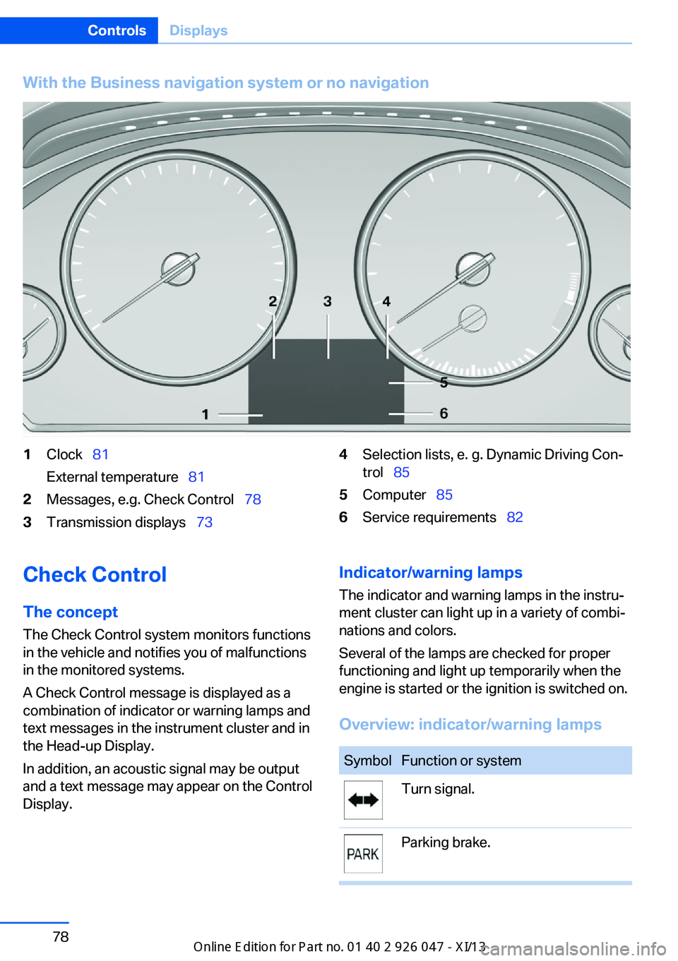
With the Business navigation system or no navigation1ClockŌĆéŌĆģ81
External temperatureŌĆéŌĆģ 812Messages, e.g. Check ControlŌĆéŌĆģ 783Transmission displaysŌĆéŌĆģ734Selection lists, e. g. Dynamic Driving ConŌĆÉ
trolŌĆéŌĆģ 855ComputerŌĆéŌĆģ 856Service requirementsŌĆéŌĆģ 82Check Control
The concept The Check Control system monitors functions
in the vehicle and notifies you of malfunctions
in the monitored systems.
A Check Control message is displayed as a
combination of indicator or warning lamps and
text messages in the instrument cluster and in
the Head-up Display.
In addition, an acoustic signal may be output
and a text message may appear on the Control Display.Indicator/warning lamps
The indicator and warning lamps in the instruŌĆÉ
ment cluster can light up in a variety of combiŌĆÉ
nations and colors.
Several of the lamps are checked for proper
functioning and light up temporarily when the
engine is started or the ignition is switched on.
Overview: indicator/warning lampsSymbolFunction or systemTurn signal.Parking brake.Seite 78ControlsDisplays78
Online Edition for Part no. 01 40 2 911 041 - VI/13
Page 83 of 212
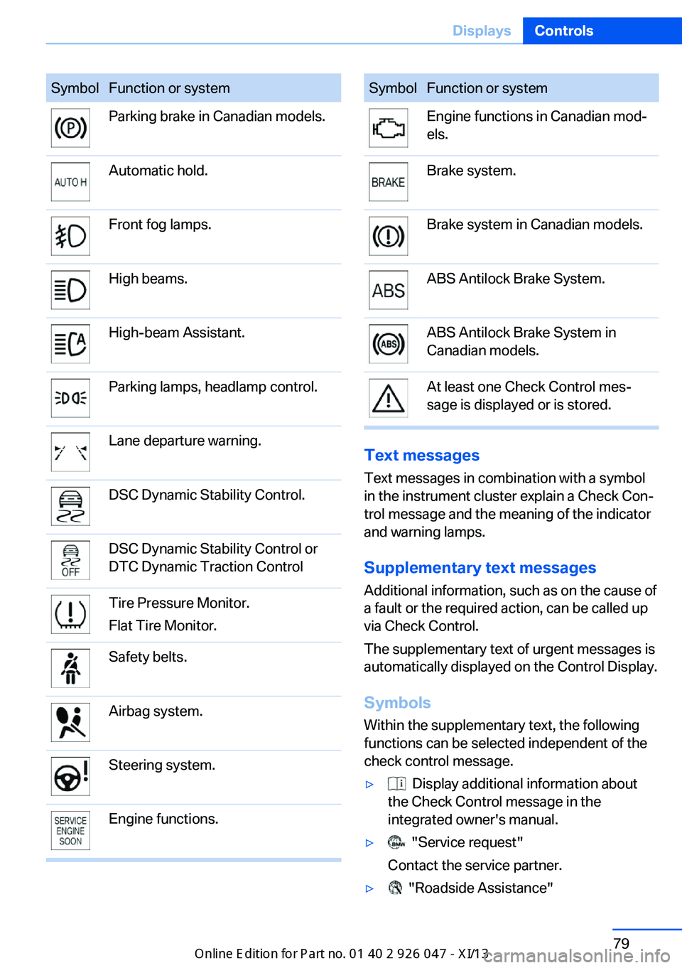
SymbolFunction or systemParking brake in Canadian models.Automatic hold.Front fog lamps.High beams.High-beam Assistant.Parking lamps, headlamp control.Lane departure warning.DSC Dynamic Stability Control.DSC Dynamic Stability Control or
DTC Dynamic Traction ControlTire Pressure Monitor.
Flat Tire Monitor.Safety belts.Airbag system.Steering system.Engine functions.SymbolFunction or systemEngine functions in Canadian modŌĆÉ
els.Brake system.Brake system in Canadian models.ABS Antilock Brake System.ABS Antilock Brake System in
Canadian models.At least one Check Control mesŌĆÉ
sage is displayed or is stored.
Text messages
Text messages in combination with a symbol
in the instrument cluster explain a Check ConŌĆÉ trol message and the meaning of the indicator
and warning lamps.
Supplementary text messages
Additional information, such as on the cause of
a fault or the required action, can be called up
via Check Control.
The supplementary text of urgent messages is
automatically displayed on the Control Display.
Symbols
Within the supplementary text, the following
functions can be selected independent of the
check control message.
Ō¢Ę Display additional information about
the Check Control message in the
integrated owner's manual.Ō¢Ę "Service request"
Contact the service partner.Ō¢Ę "Roadside Assistance"Seite 79DisplaysControls79
Online Edition for Part no. 01 40 2 911 041 - VI/13
Page 84 of 212
Contact Roadside Assistance.
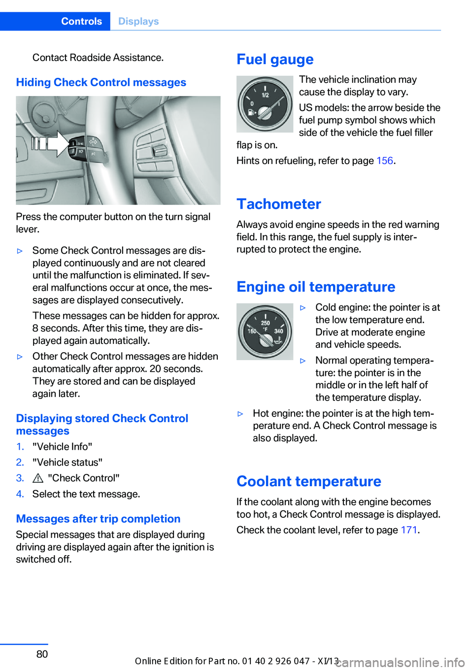
Hiding Check Control messages
Press the computer button on the turn signal
lever.
Ō¢ĘSome Check Control messages are disŌĆÉ
played continuously and are not cleared
until the malfunction is eliminated. If sevŌĆÉ
eral malfunctions occur at once, the mesŌĆÉ
sages are displayed consecutively.
These messages can be hidden for approx.
8 seconds. After this time, they are disŌĆÉ
played again automatically.Ō¢ĘOther Check Control messages are hidden
automatically after approx. 20 seconds.
They are stored and can be displayed
again later.
Displaying stored Check Control
messages
1."Vehicle Info"2."Vehicle status"3. "Check Control"4.Select the text message.
Messages after trip completion
Special messages that are displayed during
driving are displayed again after the ignition is
switched off.
Fuel gauge
The vehicle inclination may
cause the display to vary.
US models: the arrow beside the
fuel pump symbol shows which
side of the vehicle the fuel filler
flap is on.
Hints on refueling, refer to page 156.
Tachometer
Always avoid engine speeds in the red warning
field. In this range, the fuel supply is interŌĆÉ
rupted to protect the engine.
Engine oil temperatureŌ¢ĘCold engine: the pointer is at
the low temperature end.
Drive at moderate engine
and vehicle speeds.Ō¢ĘNormal operating temperaŌĆÉ
ture: the pointer is in the
middle or in the left half of
the temperature display.Ō¢ĘHot engine: the pointer is at the high temŌĆÉ
perature end. A Check Control message is
also displayed.
Coolant temperature
If the coolant along with the engine becomes
too hot, a Check Control message is displayed.
Check the coolant level, refer to page 171.
Seite 80ControlsDisplays80
Online Edition for Part no. 01 40 2 911 041 - VI/13
Page 85 of 212
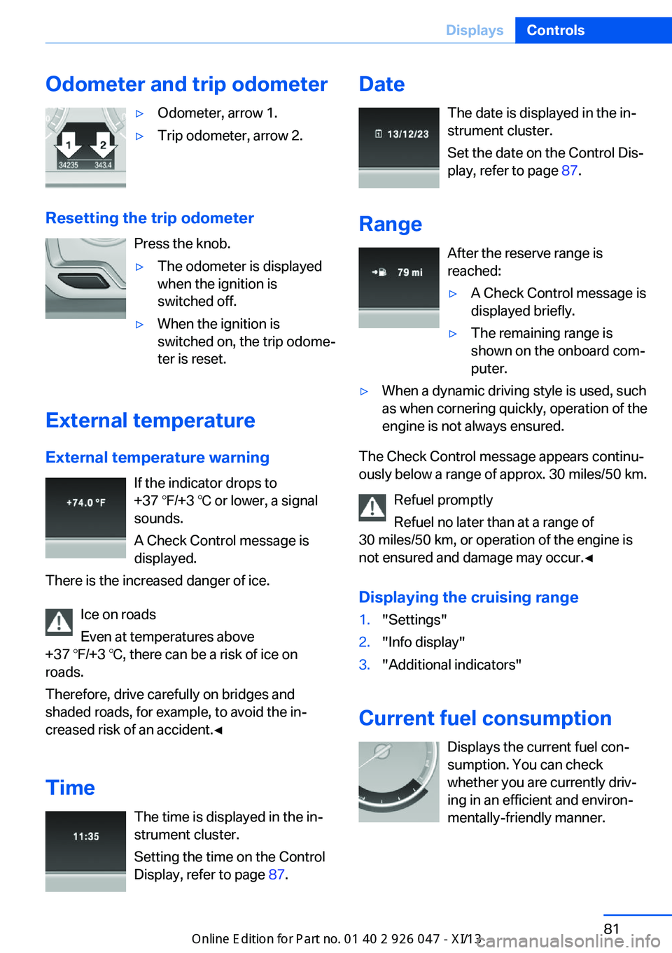
Odometer and trip odometerŌ¢ĘOdometer, arrow 1.Ō¢ĘTrip odometer, arrow 2.
Resetting the trip odometerPress the knob.
Ō¢ĘThe odometer is displayed
when the ignition is
switched off.Ō¢ĘWhen the ignition is
switched on, the trip odomeŌĆÉ
ter is reset.
External temperature
External temperature warning If the indicator drops to
+37 Ōäē/+3 Ōäā or lower, a signal
sounds.
A Check Control message is displayed.
There is the increased danger of ice.
Ice on roads
Even at temperatures above
+37 Ōäē/+3 Ōäā, there can be a risk of ice on
roads.
Therefore, drive carefully on bridges and
shaded roads, for example, to avoid the inŌĆÉ
creased risk of an accident.ŌŚĆ
Time The time is displayed in the inŌĆÉ
strument cluster.
Setting the time on the Control
Display, refer to page 87.
Date
The date is displayed in the inŌĆÉ
strument cluster.
Set the date on the Control DisŌĆÉ
play, refer to page 87.
Range After the reserve range is
reached:Ō¢ĘA Check Control message is
displayed briefly.Ō¢ĘThe remaining range is
shown on the onboard comŌĆÉ
puter.Ō¢ĘWhen a dynamic driving style is used, such
as when cornering quickly, operation of the
engine is not always ensured.
The Check Control message appears continuŌĆÉ
ously below a range of approx. 30 miles/50 km.
Refuel promptly
Refuel no later than at a range of
30 miles/50 km, or operation of the engine is
not ensured and damage may occur.ŌŚĆ
Displaying the cruising range
1."Settings"2."Info display"3."Additional indicators"
Current fuel consumption Displays the current fuel conŌĆÉ
sumption. You can check whether you are currently drivŌĆÉ
ing in an efficient and environŌĆÉ
mentally-friendly manner.
Seite 81DisplaysControls81
Online Edition for Part no. 01 40 2 911 041 - VI/13
Page 86 of 212
Displaying the current fuel
consumption1."Settings"2."Info display"3."Additional indicators"
The bar display for the current fuel consumpŌĆÉ
tion is displayed in the instrument cluster.
Energy recovery The kinetic energy of the vehicle
is converted to electrical energy while coasting. The vehicle batŌĆÉ
tery is partially charged and fuel
consumption can be reduced.
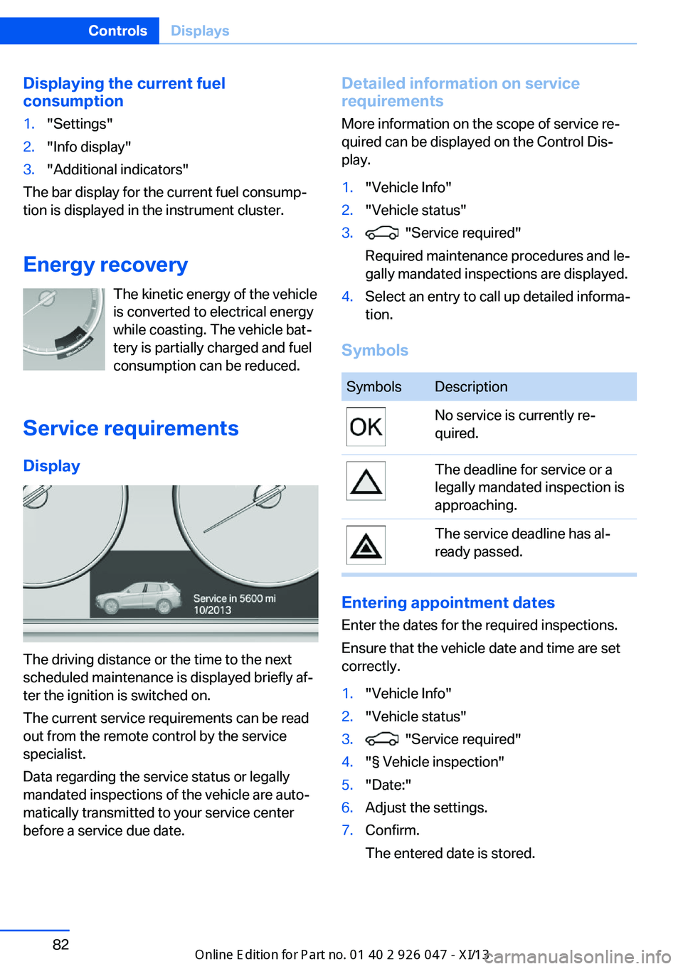
Service requirements Display
The driving distance or the time to the next
scheduled maintenance is displayed briefly afŌĆÉ
ter the ignition is switched on.
The current service requirements can be read
out from the remote control by the service
specialist.
Data regarding the service status or legally
mandated inspections of the vehicle are autoŌĆÉ
matically transmitted to your service center
before a service due date.
Detailed information on service
requirements
More information on the scope of service reŌĆÉ
quired can be displayed on the Control DisŌĆÉ
play.1."Vehicle Info"2."Vehicle status"3. "Service required"
Required maintenance procedures and leŌĆÉ
gally mandated inspections are displayed.4.Select an entry to call up detailed informaŌĆÉ
tion.
Symbols
SymbolsDescriptionNo service is currently reŌĆÉ
quired.The deadline for service or a
legally mandated inspection is
approaching.The service deadline has alŌĆÉ
ready passed.
Entering appointment dates
Enter the dates for the required inspections.
Ensure that the vehicle date and time are set
correctly.
1."Vehicle Info"2."Vehicle status"3. "Service required"4."┬¦ Vehicle inspection"5."Date:"6.Adjust the settings.7.Confirm.
The entered date is stored.Seite 82ControlsDisplays82
Online Edition for Part no. 01 40 2 911 041 - VI/13
Page 87 of 212
Automatic Service Request
Data regarding the service status or legally
mandated inspections of the vehicle are autoŌĆÉ
matically transmitted to your service center
before a service due date.
You can check when your service center was
notified.1."Vehicle Info"2."Vehicle status"3.Open "Options".4."Last Service Request"
Gear shift indicator
The conceptThe system recommends the most fuel effiŌĆÉ
cient gear in the current driving situation.
Depending on how the vehicle is equipped and
the country-specific version of the vehicle, the
gear shift indicator is active in the manual
mode of the automatic transmission and in the
manual transmission.
Indicators to shift up or down are displayed in
the instrument cluster.
On vehicles without a gear shift indicator, the
engaged gear is displayed.
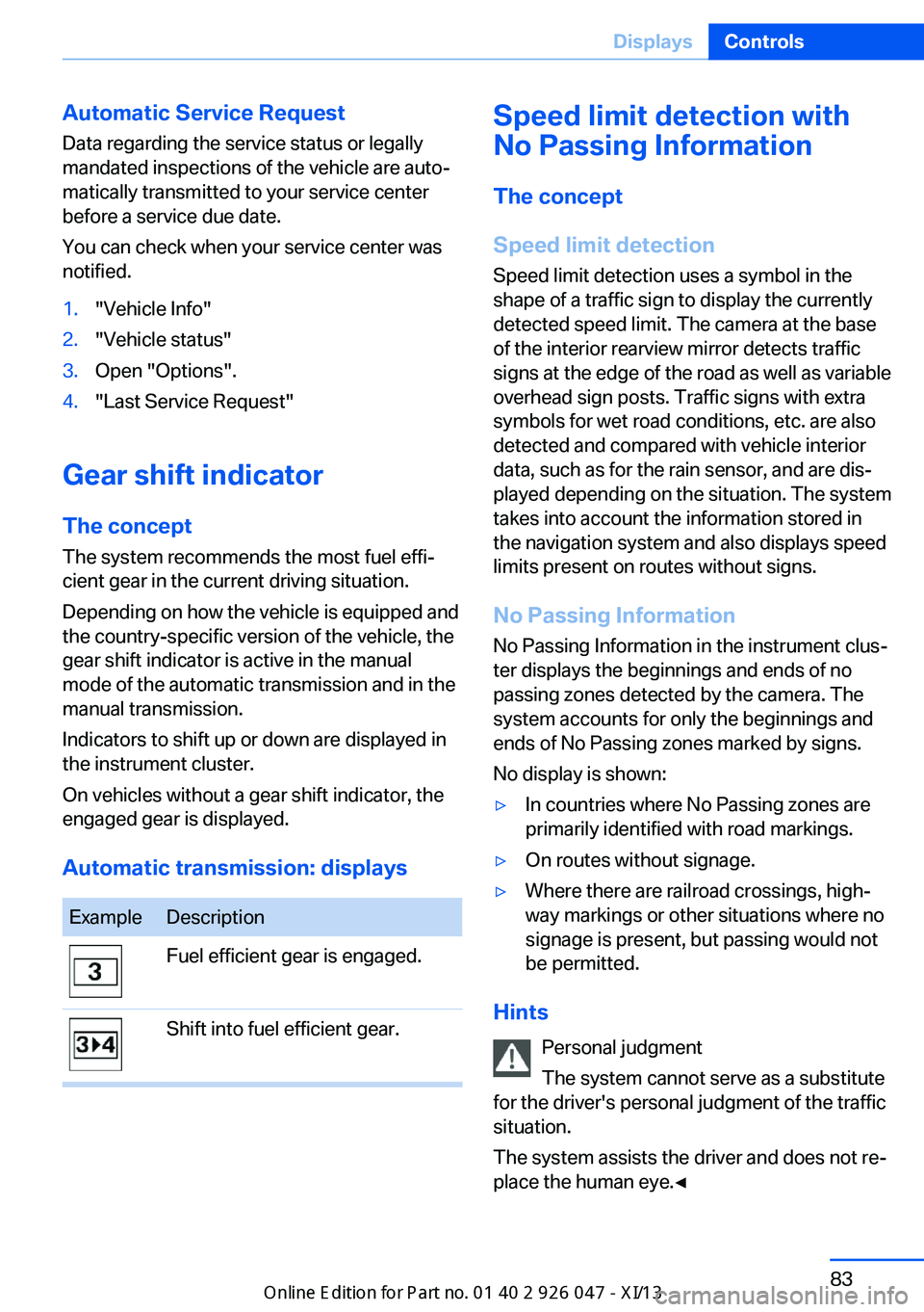
Automatic transmission: displays
ExampleDescriptionFuel efficient gear is engaged.Shift into fuel efficient gear.Speed limit detection with
No Passing Information
The concept
Speed limit detection Speed limit detection uses a symbol in the
shape of a traffic sign to display the currently
detected speed limit. The camera at the base
of the interior rearview mirror detects traffic
signs at the edge of the road as well as variable
overhead sign posts. Traffic signs with extra
symbols for wet road conditions, etc. are also
detected and compared with vehicle interior
data, such as for the rain sensor, and are disŌĆÉ
played depending on the situation. The system
takes into account the information stored in
the navigation system and also displays speed
limits present on routes without signs.
No Passing Information No Passing Information in the instrument clusŌĆÉ
ter displays the beginnings and ends of no
passing zones detected by the camera. The
system accounts for only the beginnings and
ends of No Passing zones marked by signs.
No display is shown:Ō¢ĘIn countries where No Passing zones are
primarily identified with road markings.Ō¢ĘOn routes without signage.Ō¢ĘWhere there are railroad crossings, highŌĆÉ
way markings or other situations where no
signage is present, but passing would not
be permitted.
Hints
Personal judgment
The system cannot serve as a substitute
for the driver's personal judgment of the traffic
situation.
The system assists the driver and does not reŌĆÉ
place the human eye.ŌŚĆ
Seite 83DisplaysControls83
Online Edition for Part no. 01 40 2 911 041 - VI/13
Page 88 of 212
At a glance
Camera
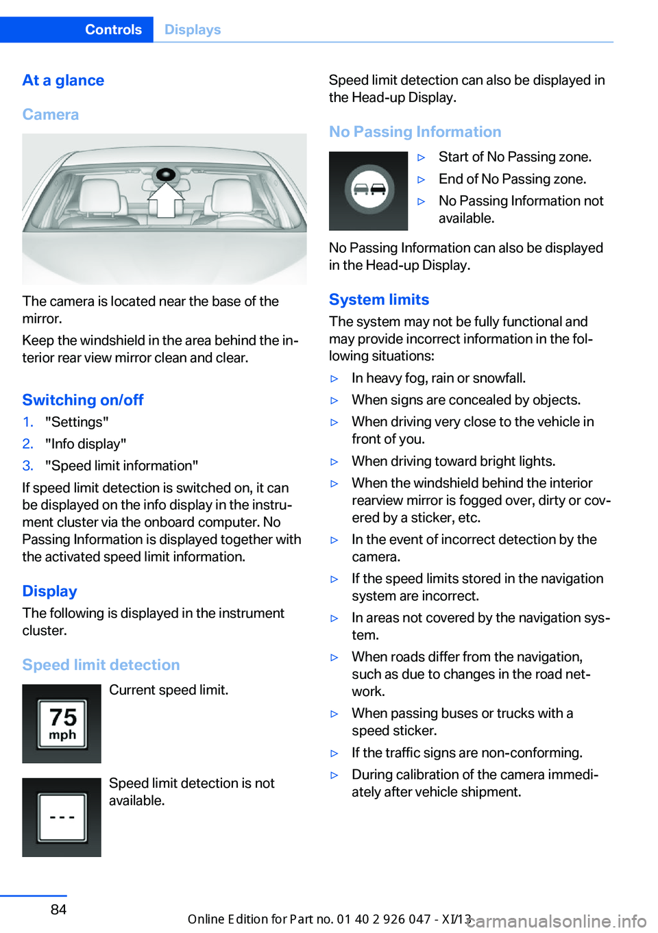
The camera is located near the base of the
mirror.
Keep the windshield in the area behind the inŌĆÉ
terior rear view mirror clean and clear.
Switching on/off
1."Settings"2."Info display"3."Speed limit information"
If speed limit detection is switched on, it can
be displayed on the info display in the instruŌĆÉ
ment cluster via the onboard computer. No
Passing Information is displayed together with
the activated speed limit information.
Display The following is displayed in the instrument
cluster.
Speed limit detection Current speed limit.
Speed limit detection is not available.
Speed limit detection can also be displayed in
the Head-up Display.
No Passing InformationŌ¢ĘStart of No Passing zone.Ō¢ĘEnd of No Passing zone.Ō¢ĘNo Passing Information not
available.
No Passing Information can also be displayed
in the Head-up Display.
System limits
The system may not be fully functional and
may provide incorrect information in the folŌĆÉ lowing situations:
Ō¢ĘIn heavy fog, rain or snowfall.Ō¢ĘWhen signs are concealed by objects.Ō¢ĘWhen driving very close to the vehicle in
front of you.Ō¢ĘWhen driving toward bright lights.Ō¢ĘWhen the windshield behind the interior
rearview mirror is fogged over, dirty or covŌĆÉ
ered by a sticker, etc.Ō¢ĘIn the event of incorrect detection by the
camera.Ō¢ĘIf the speed limits stored in the navigation
system are incorrect.Ō¢ĘIn areas not covered by the navigation sysŌĆÉ
tem.Ō¢ĘWhen roads differ from the navigation,
such as due to changes in the road netŌĆÉ
work.Ō¢ĘWhen passing buses or trucks with a
speed sticker.Ō¢ĘIf the traffic signs are non-conforming.Ō¢ĘDuring calibration of the camera immediŌĆÉ
ately after vehicle shipment.Seite 84ControlsDisplays84
Online Edition for Part no. 01 40 2 911 041 - VI/13
Page 89 of 212
Selection lists in the
instrument cluster
The concept
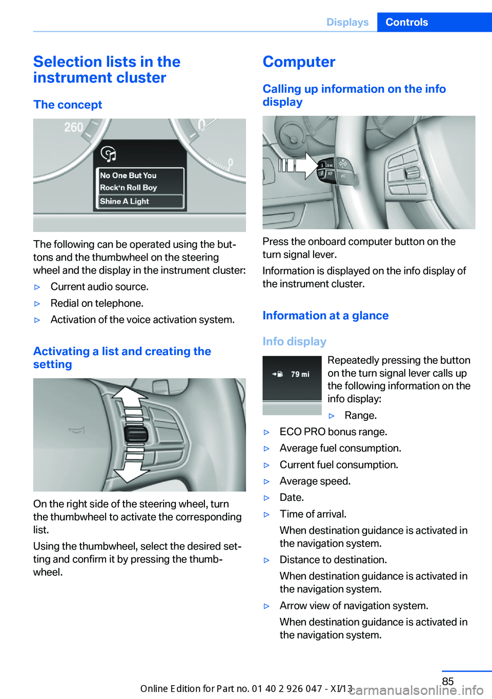
The following can be operated using the butŌĆÉ
tons and the thumbwheel on the steering
wheel and the display in the instrument cluster:
Ō¢ĘCurrent audio source.Ō¢ĘRedial on telephone.Ō¢ĘActivation of the voice activation system.
Activating a list and creating the
setting
On the right side of the steering wheel, turn
the thumbwheel to activate the corresponding
list.
Using the thumbwheel, select the desired setŌĆÉ
ting and confirm it by pressing the thumbŌĆÉ
wheel.
Computer
Calling up information on the info
display
Press the onboard computer button on the
turn signal lever.
Information is displayed on the info display of
the instrument cluster.
Information at a glance
Info display Repeatedly pressing the button
on the turn signal lever calls up
the following information on the
info display:
Ō¢ĘRange.Ō¢ĘECO PRO bonus range.Ō¢ĘAverage fuel consumption.Ō¢ĘCurrent fuel consumption.Ō¢ĘAverage speed.Ō¢ĘDate.Ō¢ĘTime of arrival.
When destination guidance is activated in
the navigation system.Ō¢ĘDistance to destination.
When destination guidance is activated in
the navigation system.Ō¢ĘArrow view of navigation system.
When destination guidance is activated in
the navigation system.Seite 85DisplaysControls85
Online Edition for Part no. 01 40 2 911 041 - VI/13
Page 90 of 212
When the arrow view in the Head-up DisŌĆÉ
play is inactive.
Adjusting the info display
You can select what information from the onŌĆÉ
board computer is to be displayed on the info
display of the instrument cluster.
1."Settings"2."Info display"3.Select the desired displays.
Information in detail
Range
Displays the estimated cruising range available
with the remaining fuel.
It is calculated based on your driving style over
the last 20 miles/30 km.
Average fuel consumption
The average fuel consumption is calculated for
the period during which the engine is running.
The average fuel consumption is calculated for
the distance traveled since the last reset by the
onboard computer.
Average speed
Periods in which the vehicle is parked with the
engine manually stopped do not enter into the
calculation of the average speed.
Resetting average values
Press and hold the computer button on the turn signal lever.
Distance to destination
The distance remaining to the destination is
displayed if a destination is entered in the naviŌĆÉ
gation system before the trip is started.
The distance to the destination is adopted auŌĆÉ
tomatically.
Time of arrival
The estimated time of arrival is
displayed if a destination is enŌĆÉ
tered in the navigation system
before the trip is started.
The time must be correctly set.
Speed limit detection
Description of the speed limit detection, refer
to page 83, function.
Speed limit
Display of a speed limit which, when reached,
should cause a warning to be issued.
The warning is repeated if the vehicle speed
drops below the set speed limit once by at least 3 mph/5 km/h.
Displaying, setting or changing the
limit1."Settings"2."Speed"3."Warning at:"4.Turn the controller until the desired limit is
displayed.5.Press the controller.
The speed limit is stored.
Activating/deactivating the limit
1."Settings"2."Speed"3."Warning"4.Press the controller.
Setting your current speed as the limit
1."Settings"2."Speed"3."Select current speed"4.Press the controller.Seite 86ControlsDisplays86
Online Edition for Part no. 01 40 2 911 041 - VI/13