tyre BMW X3 2013 F25 Owner's Manual
[x] Cancel search | Manufacturer: BMW, Model Year: 2013, Model line: X3, Model: BMW X3 2013 F25Pages: 212, PDF Size: 4.8 MB
Page 160 of 212

RefuelingVehicle equipment
All standard, country-specific and optional
equipment that is offered in the model series is
described in this chapter. Therefore, equip‐
ment is also described that is not available in a
vehicle, e. g., because of the selected optional
equipment or country variant. This also applies
for safety-related functions and systems.
General information Refuel promptly
Refuel no later than at a range of
30 miles/50 km, or operation of the engine is
not ensured and damage may occur.◀
Fuel cap
Opening1.Briefly press the rear edge of the fuel filler
flap.2.Turn the fuel cap counterclockwise.3.Place the fuel cap in the bracket attached
to the fuel filler flap.
Closing
1.Fit the cap and turn it clockwise until you
clearly hear a click.2.Close the fuel filler flap.
Do not pinch the retaining strap
Do not pinch the retaining strap attached
to the cap; otherwise, the cap cannot be
closed properly and fuel vapors can escape.
A message is displayed if the cap is loose or
missing.◀
Manually unlocking fuel filler flap In the event of an electrical malfunction, for ex‐
ample.
Seite 156MobilityRefueling156
Online Edition for Part no. 01 40 2 911 041 - VI/13
Page 178 of 212

Replacing componentsVehicle equipmentAll standard, country-specific and optional
equipment that is offered in the model series is
described in this chapter. Therefore, equip‐
ment is also described that is not available in a
vehicle, e. g., because of the selected optional
equipment or country variant. This also applies
for safety-related functions and systems.
Onboard vehicle tool kit
The onboard vehicle tool kit is located behind
the left folding cover in the cargo area.
The onboard vehicle tool kit is located under
the first aid kit behind the left folding cover in
the cargo area.
Wiper blade replacement
General information Do not fold down the wipers without
wiper blades
Do not fold down the wipers if wiper blades
have not been installed; this may damage the
windshield.◀
Front: Replacing the wiper blades1.To change the wiper blades, fold up, refer
to page 70, the wiper arms.2.Fold up the wipers.3.Position the wiper blade in a horizontal po‐
sition.4.Remove the wiper blade toward one side.5.Insert the new wiper blade in reverse order
of removal until it locks in place.6.Fold down the wipers.Seite 174MobilityReplacing components174
Online Edition for Part no. 01 40 2 911 041 - VI/13
Page 180 of 212
change, have the headlamp setting checked
and corrected by Service.
Front lamps, bulb replacement
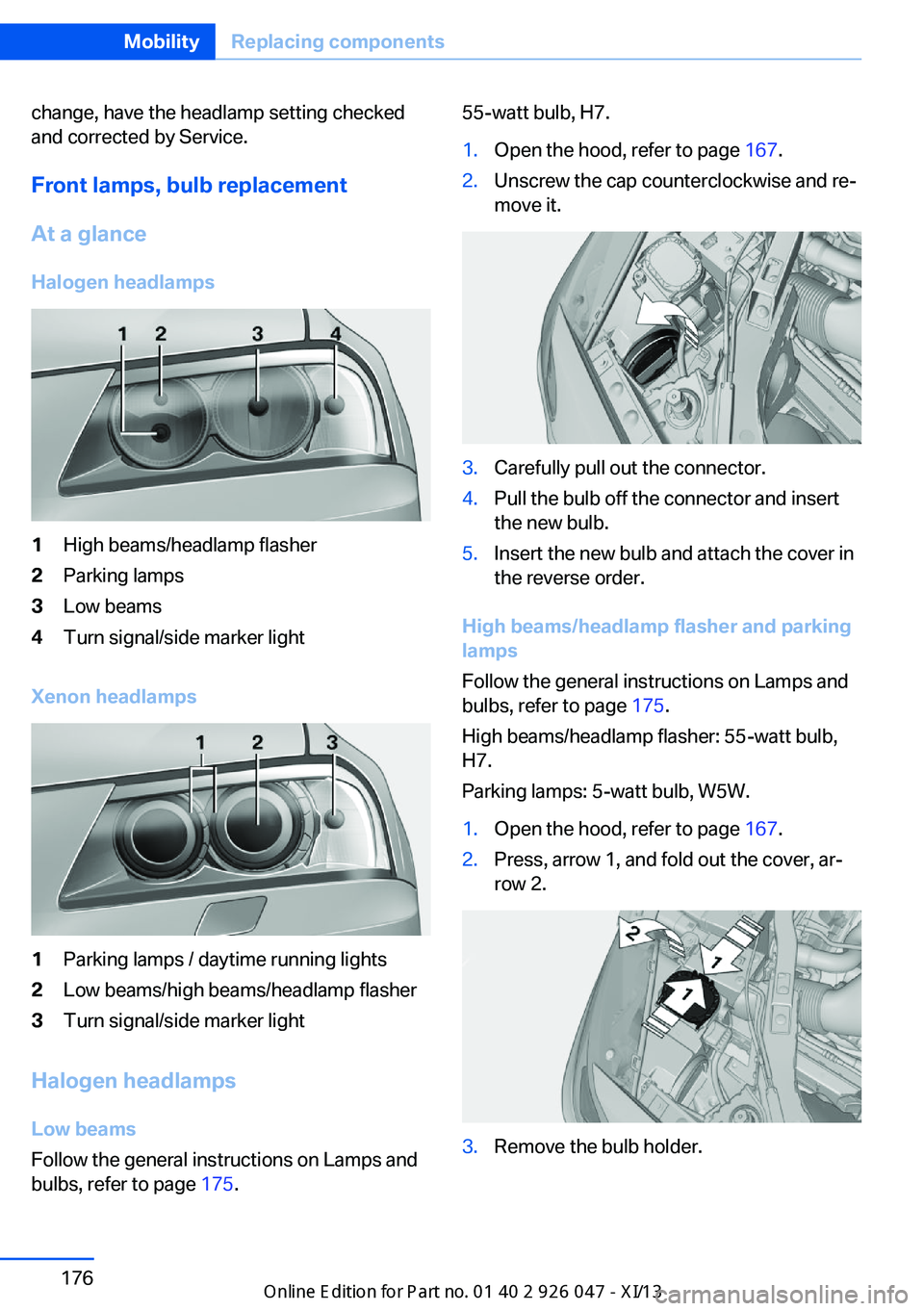
At a glance Halogen headlamps1High beams/headlamp flasher2Parking lamps3Low beams4Turn signal/side marker light
Xenon headlamps
1Parking lamps / daytime running lights2Low beams/high beams/headlamp flasher3Turn signal/side marker light
Halogen headlampsLow beams
Follow the general instructions on Lamps and
bulbs, refer to page 175.
55-watt bulb, H7.1.Open the hood, refer to page 167.2.Unscrew the cap counterclockwise and re‐
move it.3.Carefully pull out the connector.4.Pull the bulb off the connector and insert
the new bulb.5.Insert the new bulb and attach the cover in
the reverse order.
High beams/headlamp flasher and parking
lamps
Follow the general instructions on Lamps and
bulbs, refer to page 175.
High beams/headlamp flasher: 55-watt bulb,
H7.
Parking lamps: 5-watt bulb, W5W.
1.Open the hood, refer to page 167.2.Press, arrow 1, and fold out the cover, ar‐
row 2.3.Remove the bulb holder.Seite 176MobilityReplacing components176
Online Edition for Part no. 01 40 2 911 041 - VI/13
Page 182 of 212
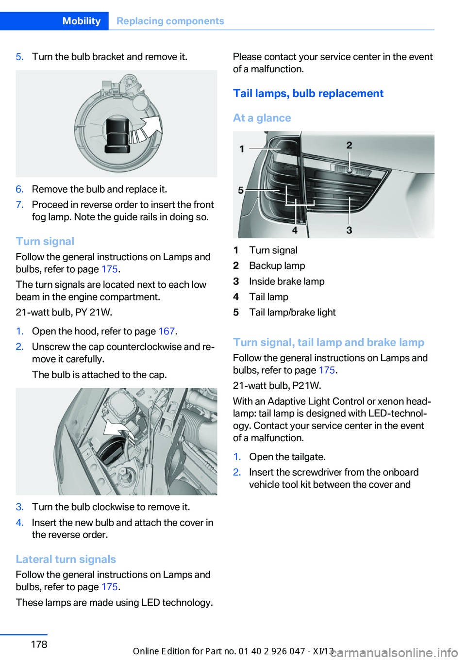
5.Turn the bulb bracket and remove it.6.Remove the bulb and replace it.7.Proceed in reverse order to insert the front
fog lamp. Note the guide rails in doing so.
Turn signal
Follow the general instructions on Lamps and
bulbs, refer to page 175.
The turn signals are located next to each low
beam in the engine compartment.
21-watt bulb, PY 21W.
1.Open the hood, refer to page 167.2.Unscrew the cap counterclockwise and re‐
move it carefully.
The bulb is attached to the cap.3.Turn the bulb clockwise to remove it.4.Insert the new bulb and attach the cover in
the reverse order.
Lateral turn signals
Follow the general instructions on Lamps and
bulbs, refer to page 175.
These lamps are made using LED technology.
Please contact your service center in the event
of a malfunction.
Tail lamps, bulb replacement
At a glance1Turn signal2Backup lamp3Inside brake lamp4Tail lamp5Tail lamp/brake light
Turn signal, tail lamp and brake lamp
Follow the general instructions on Lamps and
bulbs, refer to page 175.
21-watt bulb, P21W.
With an Adaptive Light Control or xenon head‐
lamp: tail lamp is designed with LED-technol‐
ogy. Contact your service center in the event
of a malfunction.
1.Open the tailgate.2.Insert the screwdriver from the onboard
vehicle tool kit between the cover andSeite 178MobilityReplacing components178
Online Edition for Part no. 01 40 2 911 041 - VI/13
Page 184 of 212
Changing wheels
Hints
The vehicle equipment does not include a
spare tire.
When using run-flat tires or tire sealants, a tire
does not need to be changed immediately in
the event of pressure loss due to a flat tire.
The tools for changing wheels are available as
accessories from your service center.
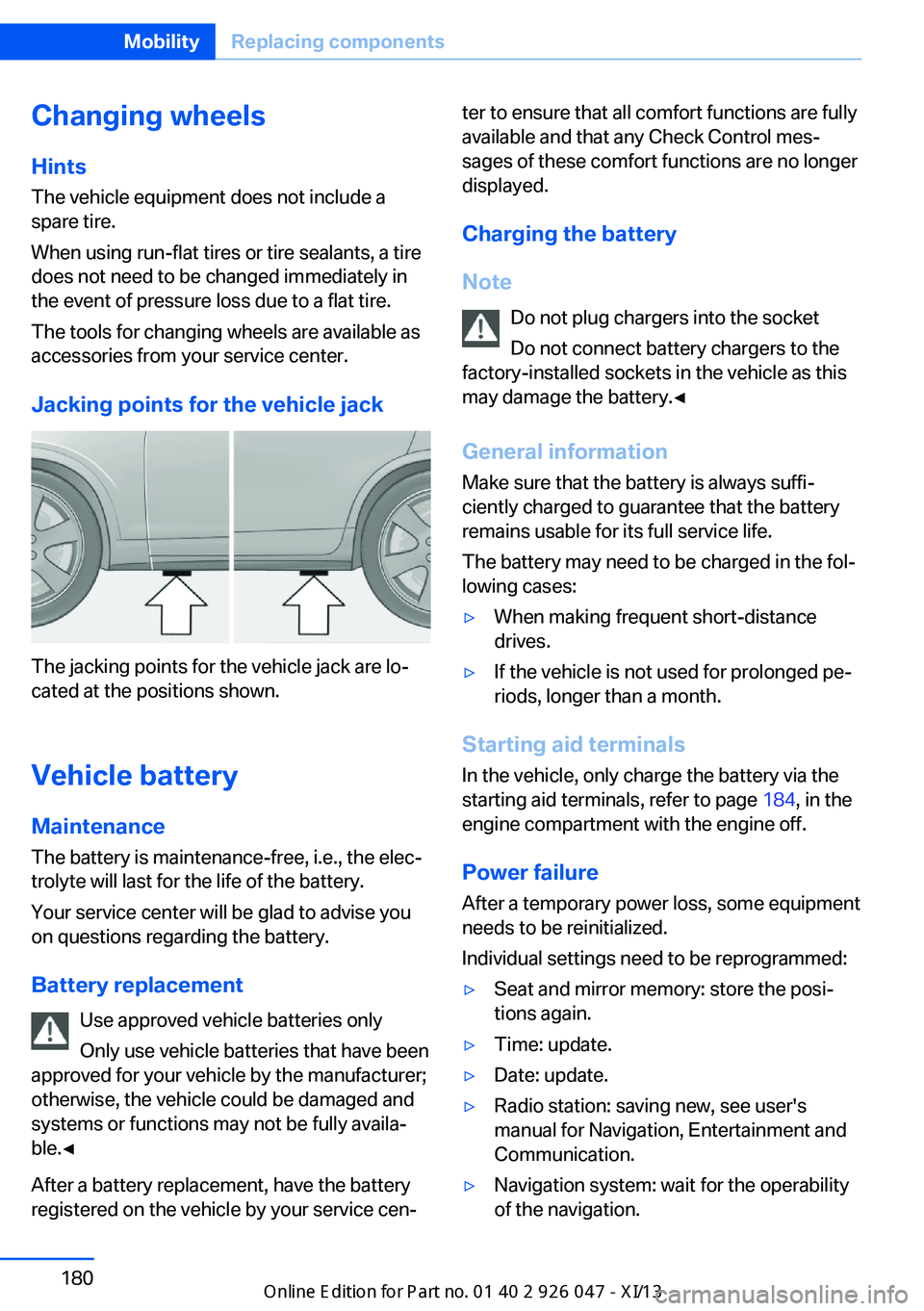
Jacking points for the vehicle jack
The jacking points for the vehicle jack are lo‐
cated at the positions shown.
Vehicle battery Maintenance
The battery is maintenance-free, i.e., the elec‐
trolyte will last for the life of the battery.
Your service center will be glad to advise you
on questions regarding the battery.
Battery replacement Use approved vehicle batteries only
Only use vehicle batteries that have been
approved for your vehicle by the manufacturer;
otherwise, the vehicle could be damaged and
systems or functions may not be fully availa‐
ble.◀
After a battery replacement, have the battery
registered on the vehicle by your service cen‐
ter to ensure that all comfort functions are fully
available and that any Check Control mes‐
sages of these comfort functions are no longer
displayed.
Charging the battery
Note Do not plug chargers into the socketDo not connect battery chargers to the
factory-installed sockets in the vehicle as this
may damage the battery.◀
General information Make sure that the battery is always suffi‐
ciently charged to guarantee that the battery
remains usable for its full service life.
The battery may need to be charged in the fol‐
lowing cases:▷When making frequent short-distance
drives.▷If the vehicle is not used for prolonged pe‐
riods, longer than a month.
Starting aid terminals
In the vehicle, only charge the battery via the
starting aid terminals, refer to page 184, in the
engine compartment with the engine off.
Power failure After a temporary power loss, some equipment
needs to be reinitialized.
Individual settings need to be reprogrammed:
▷Seat and mirror memory: store the posi‐
tions again.▷Time: update.▷Date: update.▷Radio station: saving new, see user's
manual for Navigation, Entertainment and
Communication.▷Navigation system: wait for the operability
of the navigation.Seite 180MobilityReplacing components180
Online Edition for Part no. 01 40 2 911 041 - VI/13