ESP BMW X3 2014 F25 User Guide
[x] Cancel search | Manufacturer: BMW, Model Year: 2014, Model line: X3, Model: BMW X3 2014 F25Pages: 251, PDF Size: 5.79 MB
Page 54 of 251
Danger of jamming even with pinch pro‐
tection
Despite the pinch protection system, check
that the glass sunroof's closing path is clear;
otherwise, the closing action may not be inter‐
rupted in certain extreme situations, such as
when thin objects are present.◀
Closing from the open position
without pinch protection
E. g. if there is an external danger, proceed as
follows:1.Press the reel forward beyond the resist‐
ance point and hold.
The pinch protection is limited and the
glass sunroof reopens slightly if the closing
force exceeds a certain margin.2.Press the reel forward again beyond the re‐
sistance point and hold until the glass sun‐
roof closes without jam protection. Make
sure that the closing area is clear.
Closing from the raised position
without pinch protection
If there is an external danger, push the reel for‐
ward past the resistance point and hold it.
The glass sunroof closes without jam protec‐
tion.
Initializing after a power failure After a power failure during the opening or
closing process, the glass sunroof can only be
operated to a limited extent.
Initializing the system
The system can be initialized when the vehicle
is stationary and the engine is running.
During the initialization, the glass sunroof
closes without jam protection.
Keep the closing path clear
Monitor closing and make sure that the
closing path of the glass sunroof is clear; oth‐
erwise, injuries may result.◀
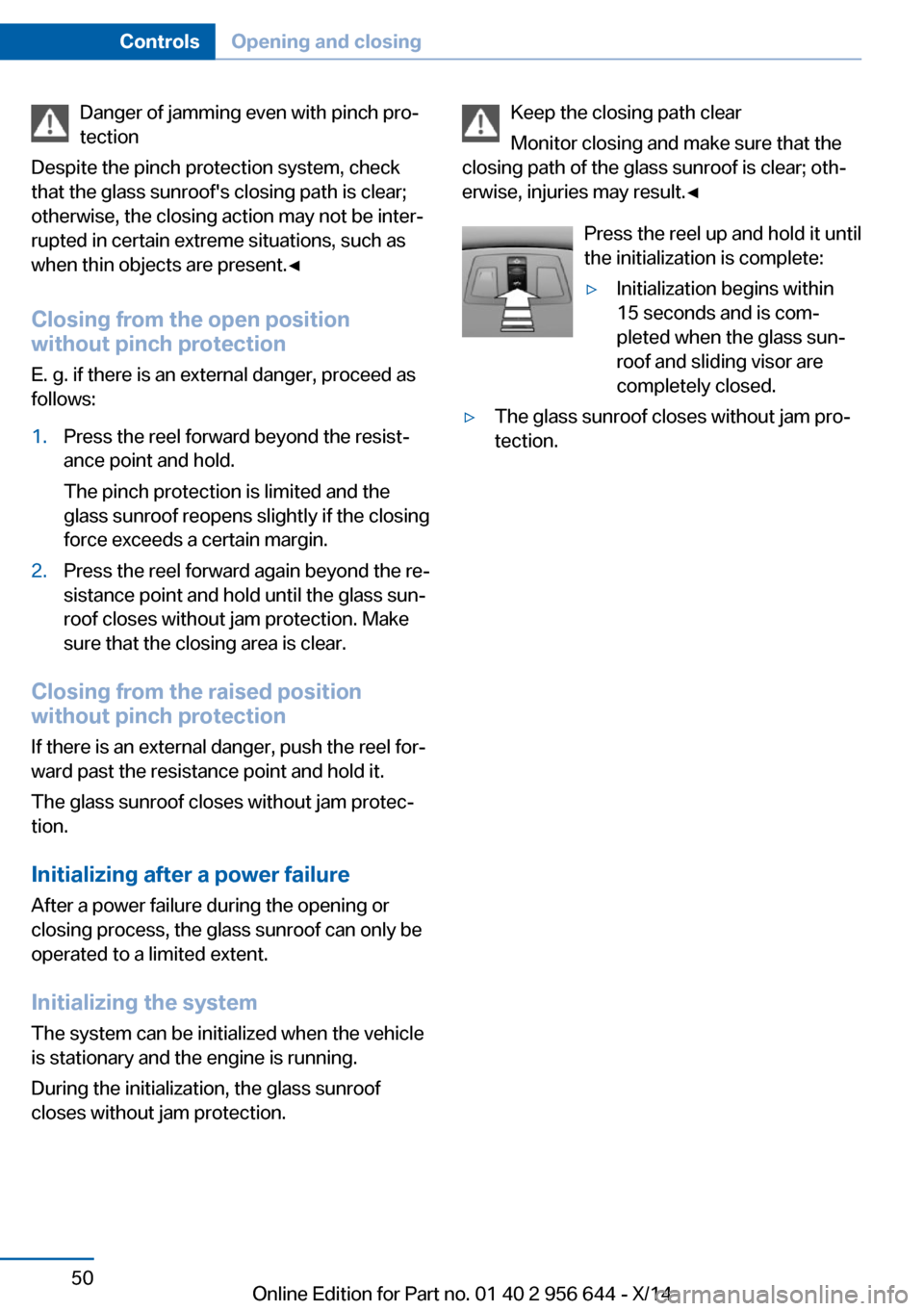
Press the reel up and hold it until
the initialization is complete:▷Initialization begins within
15 seconds and is com‐
pleted when the glass sun‐
roof and sliding visor are
completely closed.▷The glass sunroof closes without jam pro‐
tection.Seite 50ControlsOpening and closing50
Online Edition for Part no. 01 40 2 956 644 - X/14
Page 55 of 251
AdjustingVehicle features and options
This chapter describes all standard, country-
specific and optional features offered with the
series. It also describes features that are not
necessarily available in your car, e. g., due to
the selected options or country versions. This
also applies to safety-related functions and
systems.
Sitting safely
The ideal seating position can make a vital
contribution to relaxed, fatigue-free driving.
The seating position plays an important role in
an accident in combination with:▷Safety belts, refer to page 54.▷Head restraints, refer to page 55.▷Airbags, refer to page 99.
Seats
Hints Do not adjust the seat while driving
Do not adjust the driver's seat while driv‐
ing, or the seat could respond with unexpected
movement and the ensuing loss of vehicle
control could lead to an accident.◀
Do not incline the backrest too far to the
rear
Also on the front passenger side, do not incline
the backrest on the front passenger side too far to the rear while driving, or there is a risk of
slipping under the safety belt in the event of an
accident. This would eliminate the protection
normally provided by the belt.◀
Keep the movement area unobstructed
When changing the seat position, keep
the seat's area of movement unobstructed;
otherwise, people might get injured or objects
damaged.◀
Manually adjustable seats
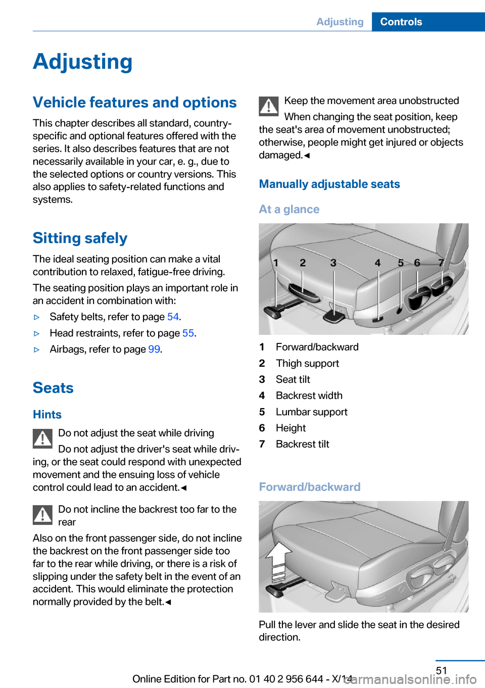
At a glance1Forward/backward2Thigh support3Seat tilt4Backrest width5Lumbar support6Height7Backrest tilt
Forward/backward
Pull the lever and slide the seat in the desired
direction.
Seite 51AdjustingControls51
Online Edition for Part no. 01 40 2 956 644 - X/14
Page 61 of 251
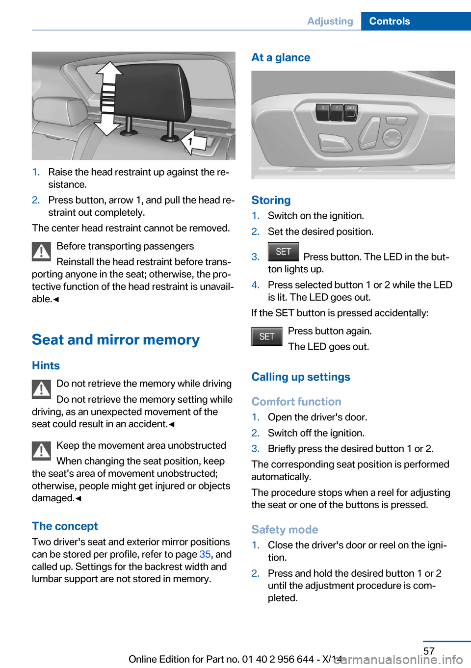
1.Raise the head restraint up against the re‐
sistance.2.Press button, arrow 1, and pull the head re‐
straint out completely.
The center head restraint cannot be removed.
Before transporting passengers
Reinstall the head restraint before trans‐
porting anyone in the seat; otherwise, the pro‐
tective function of the head restraint is unavail‐
able.◀
Seat and mirror memory
Hints Do not retrieve the memory while driving
Do not retrieve the memory setting while
driving, as an unexpected movement of the
seat could result in an accident.◀
Keep the movement area unobstructed
When changing the seat position, keep
the seat's area of movement unobstructed;
otherwise, people might get injured or objects
damaged.◀
The conceptTwo driver's seat and exterior mirror positions
can be stored per profile, refer to page 35, and
called up. Settings for the backrest width and
lumbar support are not stored in memory.
At a glance
Storing
1.Switch on the ignition.2.Set the desired position.3. Press button. The LED in the but‐
ton lights up.4.Press selected button 1 or 2 while the LED
is lit. The LED goes out.
If the SET button is pressed accidentally:
Press button again.
The LED goes out.
Calling up settings
Comfort function
1.Open the driver's door.2.Switch off the ignition.3.Briefly press the desired button 1 or 2.
The corresponding seat position is performed
automatically.
The procedure stops when a reel for adjusting
the seat or one of the buttons is pressed.
Safety mode
1.Close the driver's door or reel on the igni‐
tion.2.Press and hold the desired button 1 or 2
until the adjustment procedure is com‐
pleted.Seite 57AdjustingControls57
Online Edition for Part no. 01 40 2 956 644 - X/14
Page 62 of 251
Calling up of a seat position
deactivated
After a brief period, calling up stored seat posi‐
tions is deactivated to save battery power.
To reactivate calling up of a seat position:▷Open or close the door or tailgate.▷Press a button on the remote control.▷Press the Start/Stop button.
Mirrors
Exterior mirrors
General information The mirror on the passenger side is more
curved than the driver's side mirror.
Depending on the vehicle equipment, the mir‐
ror setting is stored for the profile currently in
use. When the vehicle is unlocked via the re‐
mote control, the position is automatically re‐
trieved if this function is active.
Note Estimating distances correctly
Objects reflected in the mirror are closer
than they appear. Do not estimate the distance
to the traffic behind you based on what you
see in the mirror, as this will increase your risk
of an accident.◀
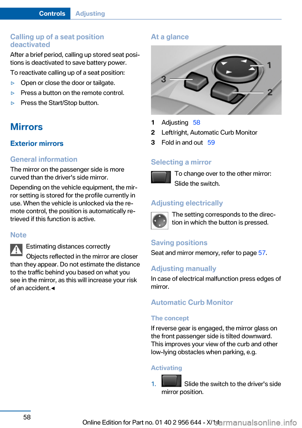
At a glance1Adjusting 582Left/right, Automatic Curb Monitor3Fold in and out 59
Selecting a mirror
To change over to the other mirror:
Slide the switch.
Adjusting electrically The setting corresponds to the direc‐
tion in which the button is pressed.
Saving positions
Seat and mirror memory, refer to page 57.
Adjusting manually
In case of electrical malfunction press edges of
mirror.
Automatic Curb MonitorThe concept
If reverse gear is engaged, the mirror glass on
the front passenger side is tilted downward.
This improves your view of the curb and other
low-lying obstacles when parking, e.g.
Activating
1. Slide the switch to the driver's side
mirror position.
Seite 58ControlsAdjusting58
Online Edition for Part no. 01 40 2 956 644 - X/14
Page 67 of 251
formation from the system manufacturer; oth‐
erwise, the level of protection may be re‐
duced.◀
Mounts for the lower LATCH anchors The lower anchors may be used to attach the
CRS to the vehicle seat up to a combined child
and CRS weight of 65 lb/30 kg when the child
is restrained by the internal harnesses.
Properly engage the lower LATCH an‐
chors
Make sure that the lower LATCH anchors have
properly engaged and that the child restraint
system is resting snugly against the backrest;
otherwise, the degree of protection may be re‐
duced.◀
Before mounting the LATCH child restraint
system, pull the belt away from the child re‐
straint system.
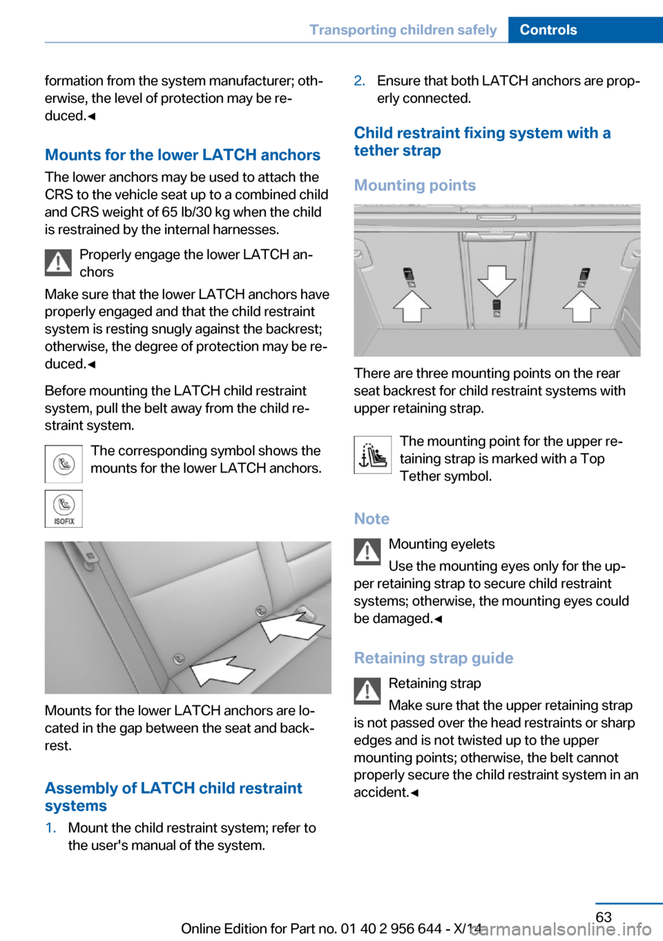
The corresponding symbol shows the
mounts for the lower LATCH anchors.
Mounts for the lower LATCH anchors are lo‐
cated in the gap between the seat and back‐
rest.
Assembly of LATCH child restraint
systems
1.Mount the child restraint system; refer to
the user's manual of the system.2.Ensure that both LATCH anchors are prop‐
erly connected.
Child restraint fixing system with a
tether strap
Mounting points
There are three mounting points on the rear
seat backrest for child restraint systems with
upper retaining strap.
The mounting point for the upper re‐
taining strap is marked with a Top
Tether symbol.
Note Mounting eyelets
Use the mounting eyes only for the up‐
per retaining strap to secure child restraint
systems; otherwise, the mounting eyes could
be damaged.◀
Retaining strap guide Retaining strap
Make sure that the upper retaining strap
is not passed over the head restraints or sharp
edges and is not twisted up to the upper
mounting points; otherwise, the belt cannot
properly secure the child restraint system in an
accident.◀
Seite 63Transporting children safelyControls63
Online Edition for Part no. 01 40 2 956 644 - X/14
Page 69 of 251
DrivingVehicle features and options
This chapter describes all standard, country-
specific and optional features offered with the
series. It also describes features that are not
necessarily available in your car, e. g., due to
the selected options or country versions. This
also applies to safety-related functions and
systems.
Start/Stop button
The concept Pressing the Start/Stop button
switches the ignition on or off
and starts the engine.
Steptronic transmission: The
engine starts if the brakes are
stepped on while pressing the Start/Stop but‐
ton.
Ignition onSteptronic transmission: Press the Start/Stop
button without stepping on the brake.
All vehicle systems are ready for operation.
Most of the indicator and warning lights in the
instrument cluster light up for a varied length
of time.
To save battery power when the engine is off,
reel off the ignition and any unnecessary elec‐
tronic systems/power consumers.
Note If the engine is switched off and the ignition is
switched on, the system automatically
switches to the radio-ready state if the lights
are turned off or, if correspondingly equipped,
the daytime running lights are activated.Ignition off
Steptronic transmission: Press the Start/Stop
button again without stepping on the brake.
All indicator lights in the instrument cluster go
out.
To save battery power when the engine is off,
reel off the ignition and any unnecessary elec‐
tronic systems/power consumers.
P when the ignition is switched off
P is engaged automatically when the ig‐
nition is switched off. When in an automatic car wash, e.g., ensure that the ignition is not
switched off accidentally.◀
The ignition automatically cuts off while the
vehicle is stationary and the engine is stopped:▷When locking the vehicle, and when the
low beams are activated.▷Shortly before the battery is discharged
completely, so that the engine can still be
started. This function is only available
when the low beams are turned off.▷When opening or closing the driver door, if
the driver's safety belt is unbuckled and
the low beams are turned off.▷While the driver's safety belt is unbuckled
with driver's door open and low beams off.
The low beams reel to parking lights after ap‐
prox. 15 minutes of no use.
Radio ready state
Activate radio-ready state:
▷When the engine is running: press the
Start/Stop button.
Some electronic systems/power consumers
remain ready for operation.
The radio-ready state switches off automati‐
cally:
▷After approx. 8 minutes.Seite 65DrivingControls65
Online Edition for Part no. 01 40 2 956 644 - X/14
Page 81 of 251
The selected gear is briefly displayed in the in‐
strument cluster, followed by the currently se‐
lected gear.
Steptronic Sport transmission:
prevent automatic upshifting in M/S
manual mode
In cars with Steptronic Sport transmission, au‐
tomatic shift operations are not performed e.g.
at maximum engine speed, if one of the follow‐
ing conditions is met:▷DSC deactivated.▷TRACTION activated.▷SPORT+ activated.
In addition, the kickdown is deactivated.
Ending the sport program/manual
mode
Push the selector lever to the right.
D is displayed in the instrument cluster.
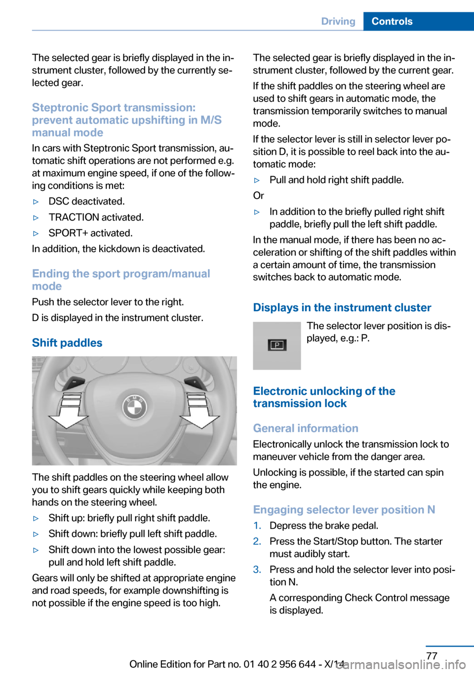
Shift paddles
The shift paddles on the steering wheel allow
you to shift gears quickly while keeping both
hands on the steering wheel.
▷Shift up: briefly pull right shift paddle.▷Shift down: briefly pull left shift paddle.▷Shift down into the lowest possible gear:
pull and hold left shift paddle.
Gears will only be shifted at appropriate engine
and road speeds, for example downshifting is
not possible if the engine speed is too high.
The selected gear is briefly displayed in the in‐
strument cluster, followed by the current gear.
If the shift paddles on the steering wheel are
used to shift gears in automatic mode, the
transmission temporarily switches to manual
mode.
If the selector lever is still in selector lever po‐
sition D, it is possible to reel back into the au‐
tomatic mode:▷Pull and hold right shift paddle.
Or
▷In addition to the briefly pulled right shift
paddle, briefly pull the left shift paddle.
In the manual mode, if there has been no ac‐
celeration or shifting of the shift paddles within
a certain amount of time, the transmission
switches back to automatic mode.
Displays in the instrument cluster The selector lever position is dis‐played, e.g.: P.
Electronic unlocking of the
transmission lock
General information Electronically unlock the transmission lock to
maneuver vehicle from the danger area.
Unlocking is possible, if the started can spin
the engine.
Engaging selector lever position N
1.Depress the brake pedal.2.Press the Start/Stop button. The starter
must audibly start.3.Press and hold the selector lever into posi‐
tion N.
A corresponding Check Control message
is displayed.Seite 77DrivingControls77
Online Edition for Part no. 01 40 2 956 644 - X/14
Page 92 of 251
▷When the windshield behind the interior
rearview mirror is fogged over, dirty or cov‐
ered by a sticker, etc.▷In the event of incorrect detection by the
camera.▷If the speed limits stored in the navigation
system are incorrect.▷In areas not covered by the navigation sys‐
tem.▷When roads differ from the navigation,
such as due to changes in road routing.▷When passing buses or trucks with a
speed sticker.▷If the traffic signs are non-conforming.▷During calibration of the camera immedi‐
ately after vehicle shipment.
Selection lists in the
instrument cluster
The concept Depending on your vehicle's optional features,
the following can be displayed or operated us‐
ing the buttons and the thumbwheel on the
steering wheel as well as the displays in the in‐
strument cluster and the Head-up Display:
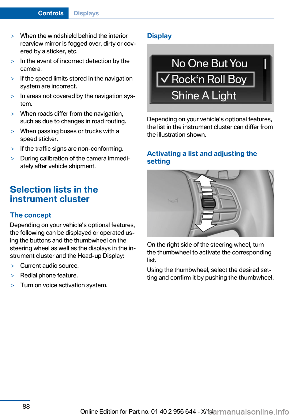
▷Current audio source.▷Redial phone feature.▷Turn on voice activation system.Display
Depending on your vehicle's optional features,
the list in the instrument cluster can differ from
the illustration shown.
Activating a list and adjusting the
setting
On the right side of the steering wheel, turn
the thumbwheel to activate the corresponding
list.
Using the thumbwheel, select the desired set‐
ting and confirm it by pushing the thumbwheel.
Seite 88ControlsDisplays88
Online Edition for Part no. 01 40 2 956 644 - X/14
Page 99 of 251
Headlight courtesy delay featureThe low beams stay lit for a short while after
the radio-ready state is switched off if the
lights are turned off and the headlight flasher is
switched on.
Setting the duration1."Settings"2."Lighting"3."Pathway lighting:"4.Set length of time.
Settings are stored for the profile currently in
use.
Automatic headlight control
Position of switch
: the low beams are acti‐
vated and off automatically, e.g., in tunnels, in
twilight or if there is precipitation. The indicator
lamp in the instrument cluster lights up.
When emerging from a tunnel during the day,
the low beams are not switched off immedi‐
ately but instead only after approx. 2 minutes.
A blue sky with the sun low on the horizon can
cause the lights to be switched on.
The low beams always stay on when the fog
lights are activated.
Personal responsibility
The automatic headlight control cannot
serve as a substitute for your personal judg‐
ment in determining when to turn the lights on
in response to ambient lighting conditions.
E. g. the sensors are unable to detect fog or
hazy weather. To avoid safety risks under
these conditions, you should always switch on
the lights manually.◀
Daytime running lights With the ignition switched on, the daytime run‐
ning lights light up in position 0,
or .
After the ignition is switched off, the parking
lights light up in position
.
Activating/deactivating
In some countries, daytime running lights are
mandatory, so it may not be possible to deacti‐
vate the daytime running lights.1."Settings"2."Lighting"3."Daytime running lamps"
Settings are stored for the profile currently in
use.
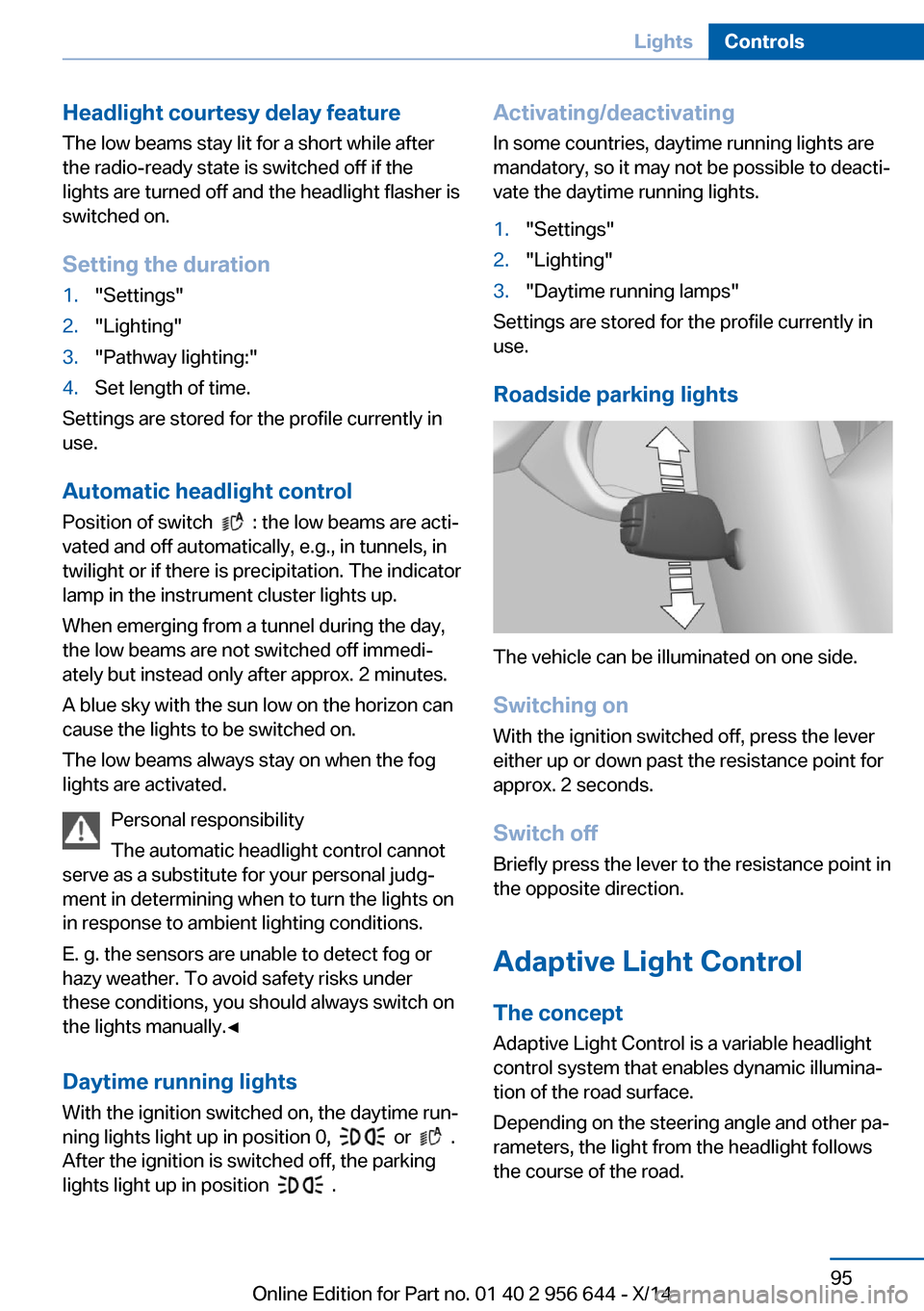
Roadside parking lights
The vehicle can be illuminated on one side.
Switching on With the ignition switched off, press the lever
either up or down past the resistance point for
approx. 2 seconds.
Switch off Briefly press the lever to the resistance point in
the opposite direction.
Adaptive Light Control The concept
Adaptive Light Control is a variable headlight
control system that enables dynamic illumina‐
tion of the road surface.
Depending on the steering angle and other pa‐ rameters, the light from the headlight follows
the course of the road.
Seite 95LightsControls95
Online Edition for Part no. 01 40 2 956 644 - X/14
Page 100 of 251
ActivatingPosition of switch
with the ignition
switched on.
To avoid blinding oncoming traffic, the Adap‐
tive Light Control does not swivel to the driv‐
er's side when the vehicle is at a standstill.
The turning lights are automatically switched
on depending on the steering angle or the use
of turn signals.
When driving in reverse, the turning lights may
be automatically switched on regardless of the
steering angle.
Self-leveling headlights The self-leveling headlights compensate for
acceleration and braking operations in order
not to blind the oncoming traffic and to achieve
optimum illumination of the roadway.
Malfunction A Check Control message is displayed.
Adaptive Light Control is malfunctioning or has
failed. Have the system checked as soon as
possible.
High-beam Assistant
The concept When the low beams are activated, this system
automatically switches the high beams on and
off or suppresses the light in the areas that
blind oncoming traffic. The procedure is con‐
trolled by a camera on the front of the interior
rearview mirror. The assistant ensures that the
high beams are activated whenever the traffic
situation allows. The driver can intervene at
any time and reel the high beams on and off as
usual.
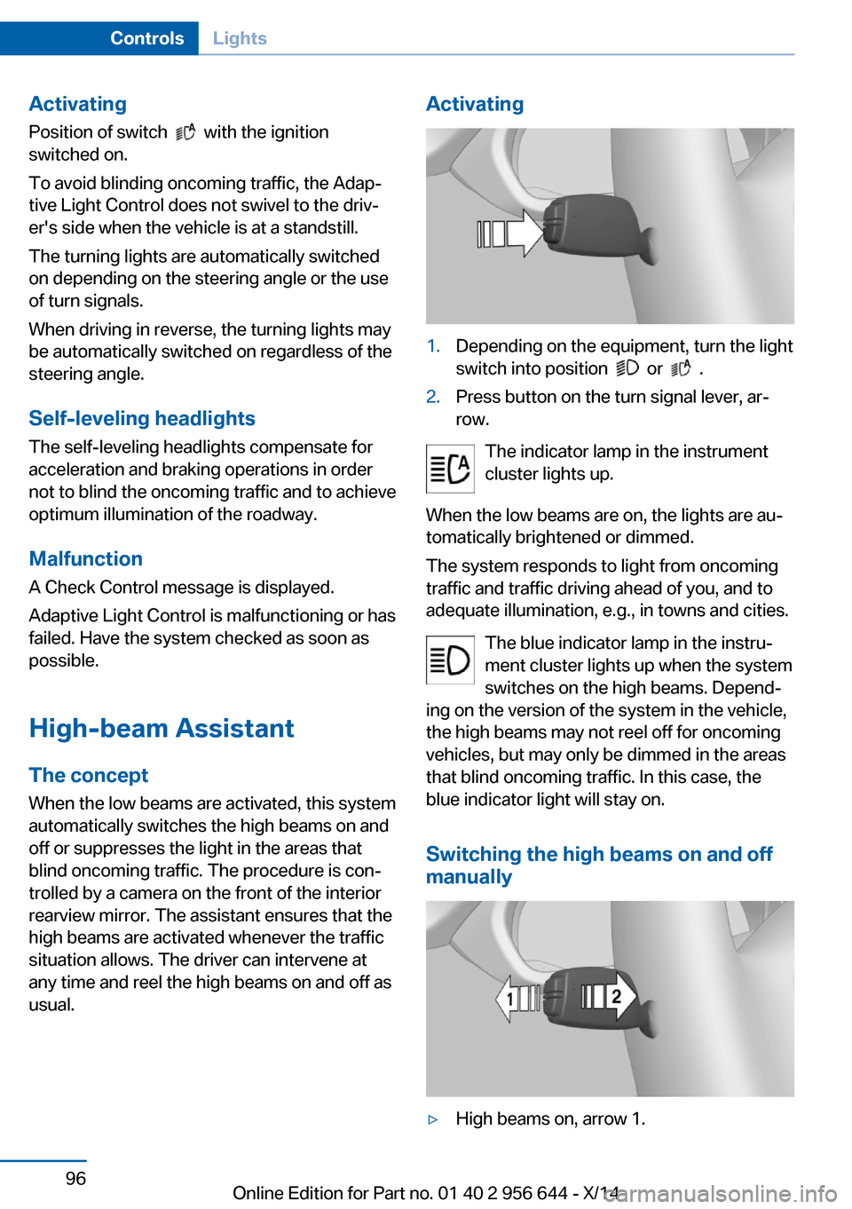
Activating1.Depending on the equipment, turn the light
switch into position
or .
2.Press button on the turn signal lever, ar‐
row.
The indicator lamp in the instrument
cluster lights up.
When the low beams are on, the lights are au‐
tomatically brightened or dimmed.
The system responds to light from oncoming
traffic and traffic driving ahead of you, and to
adequate illumination, e.g., in towns and cities.
The blue indicator lamp in the instru‐
ment cluster lights up when the system
switches on the high beams. Depend‐
ing on the version of the system in the vehicle, the high beams may not reel off for oncoming
vehicles, but may only be dimmed in the areas
that blind oncoming traffic. In this case, the blue indicator light will stay on.
Switching the high beams on and off manually
▷High beams on, arrow 1.Seite 96ControlsLights96
Online Edition for Part no. 01 40 2 956 644 - X/14