brake lamp BMW X3 2014 F25 Owner's Manual
[x] Cancel search | Manufacturer: BMW, Model Year: 2014, Model line: X3, Model: BMW X3 2014 F25Pages: 251, PDF Size: 5.79 MB
Page 73 of 251
Malfunction
The Auto Start/Stop function no longer
switches off the engine automatically. A Check Control message is displayed. It is possible to
continue driving. Have the system checked.
Parking brake The conceptThe parking brake is used to prevent the vehi‐
cle from rolling when it is parked.
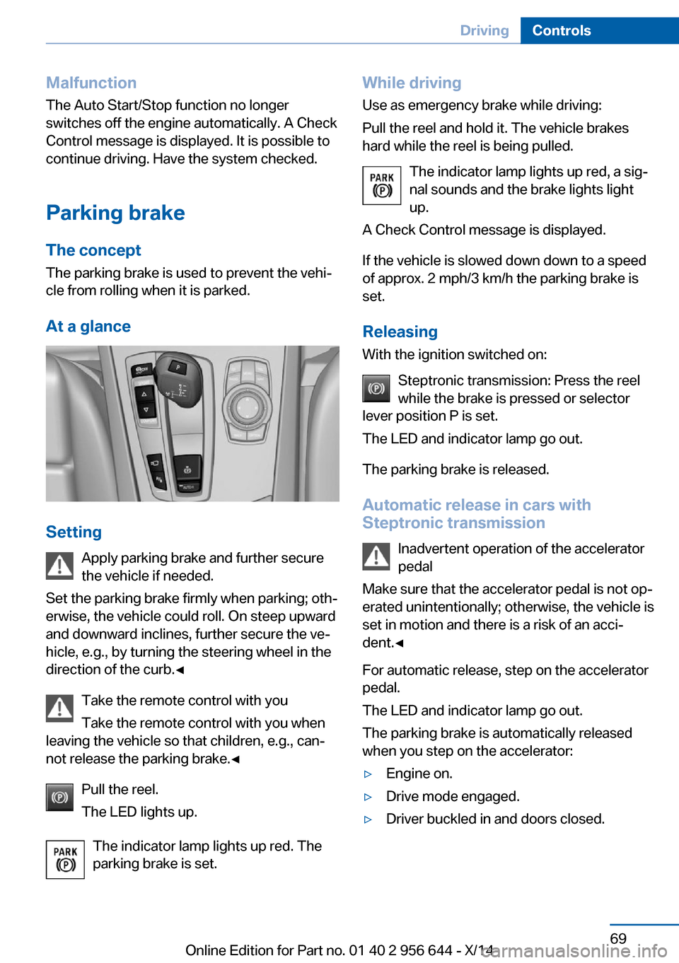
At a glance
Setting Apply parking brake and further secure
the vehicle if needed.
Set the parking brake firmly when parking; oth‐
erwise, the vehicle could roll. On steep upward
and downward inclines, further secure the ve‐
hicle, e.g., by turning the steering wheel in the
direction of the curb.◀
Take the remote control with you
Take the remote control with you when
leaving the vehicle so that children, e.g., can‐
not release the parking brake.◀
Pull the reel.
The LED lights up.
The indicator lamp lights up red. The
parking brake is set.
While driving
Use as emergency brake while driving:
Pull the reel and hold it. The vehicle brakes
hard while the reel is being pulled.
The indicator lamp lights up red, a sig‐
nal sounds and the brake lights light
up.
A Check Control message is displayed.
If the vehicle is slowed down down to a speed
of approx. 2 mph/3 km/h the parking brake is
set.
Releasing
With the ignition switched on:
Steptronic transmission: Press the reel
while the brake is pressed or selector
lever position P is set.
The LED and indicator lamp go out.
The parking brake is released.
Automatic release in cars with
Steptronic transmission
Inadvertent operation of the accelerator
pedal
Make sure that the accelerator pedal is not op‐
erated unintentionally; otherwise, the vehicle is
set in motion and there is a risk of an acci‐
dent.◀
For automatic release, step on the accelerator
pedal.
The LED and indicator lamp go out.
The parking brake is automatically released
when you step on the accelerator:▷Engine on.▷Drive mode engaged.▷Driver buckled in and doors closed.Seite 69DrivingControls69
Online Edition for Part no. 01 40 2 956 644 - X/14
Page 74 of 251
Automatic Hold
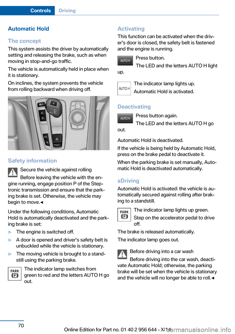
The concept This system assists the driver by automatically
setting and releasing the brake, such as when
moving in stop-and-go traffic.
The vehicle is automatically held in place when
it is stationary.
On inclines, the system prevents the vehicle
from rolling backward when driving off.
Safety information
Secure the vehicle against rolling
Before leaving the vehicle with the en‐
gine running, engage position P of the Step‐
tronic transmission and ensure that the park‐
ing brake is set. Otherwise, the vehicle may
begin to move.◀
Under the following conditions, Automatic
Hold is automatically deactivated and the park‐
ing brake is set:
▷The engine is switched off.▷A door is opened and driver's safety belt is
unbuckled while the vehicle is stationary.▷The moving vehicle is brought to a stand‐
still using the parking brake.
The indicator lamp switches from
green to red and the letters AUTO H go out.
Activating
This function can be activated when the driv‐
er's door is closed, the safety belt is fastened
and the engine is running.
Press button.
The LED and the letters AUTO H light
up.
The indicator lamp lights up.
Automatic Hold is activated.
Deactivating Press button again.
The LED and the letters AUTO H go
out.
Automatic Hold is deactivated.
If the vehicle is being held by Automatic Hold,
press on the brake pedal to deactivate it.
When the parking brake is set manually, Auto‐
matic Hold is deactivated automatically.
sDriving Automatic Hold is activated: the vehicle is au‐
tomatically secured against rolling after brak‐
ing to a standstill.
The indicator lamp lights up green.
Step on the accelerator pedal to drive
off.
The brake is released automatically.
The indicator lamp goes out.
Before driving into a car wash
Before driving into the car wash, deacti‐
vate Automatic Hold; otherwise, the parking
brake will be set when the vehicle is stationary
and the vehicle will no longer be able to roll.◀Seite 70ControlsDriving70
Online Edition for Part no. 01 40 2 956 644 - X/14
Page 75 of 251
Parking
The parking brake is automatically set if the
engine is switched off while the vehicle is be‐
ing held by Automatic Hold.
The indicator lamp changes from green
to red.
The parking brake is not set if the en‐
gine is switched off while the vehicle is coast‐
ing to a halt. Automatic Hold is deactivated.
Automatic Hold remains activated during the
engine stop brought about by the Auto Start/
Stop function.
Take the remote control with you
Take the remote control with you when
leaving the vehicle so that children, e.g., can‐
not release the parking brake.◀
Malfunction In the event of a failure or malfunction of the
parking brake, secure the vehicle against roll‐
ing using a wheel chock, e.g., when leaving it.
After a power failure
Putting the parking brake into
operation1.Switch on the ignition.2. Press the reel while stepping on the
brake pedal or selector lever position P is
set.
It may take several seconds for the brake to be
put into operation. Any sounds associated with
this are normal.
The indicator lamp in the instrument
cluster goes out as soon as the parking
brake is ready for operation.
Turn signal, high beams,
headlight flasher
Turn signal Do not adjust the exterior mirrors
Do not adjust the exterior mirror while
driving and when blinker/hazards are on, or
else the additional blinker lights in the exterior
mirror are out of position and can't be seen.◀
Using turn signals
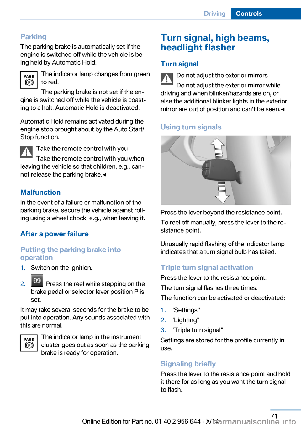
Press the lever beyond the resistance point.
To reel off manually, press the lever to the re‐
sistance point.
Unusually rapid flashing of the indicator lamp
indicates that a turn signal bulb has failed.
Triple turn signal activation Press the lever to the resistance point.
The turn signal flashes three times.
The function can be activated or deactivated:
1."Settings"2."Lighting"3."Triple turn signal"
Settings are stored for the profile currently in
use.
Signaling briefly
Press the lever to the resistance point and hold
it there for as long as you want the turn signal
to flash.
Seite 71DrivingControls71
Online Edition for Part no. 01 40 2 956 644 - X/14
Page 82 of 251
4.Press the selector lever again into posi‐
tion N within approx. 6 seconds.
Position N is displayed in the instrument
cluster.5.Release brake, as soon as the starter
stops.6.Maneuver the vehicle from the danger area
and secure it against moving on its own.
Steptronic Sport transmission:
Launch Control
The concept Launch Control enables optimum accelerationon surfaces with good traction.
Hints Component wear
Do not use Launch Control too often;
otherwise, this may result in premature wear of
components due to the high stress placed on
the vehicle.◀
Do not use Launch Control during the break-in,
refer to page 172, period.
To increase vehicle stability, activate DSC
again as soon as possible.
An experienced driver may be able to achieve
better acceleration values in DSC OFF mode.
Requirements Launch Control is available when the engine is
warmed up, that is, after uninterrupted driving
of at least 6 miles/10 km.
To start with Launch Control do not steer the
steering wheel.
Start with launch controlWhile the engine is running:
1. Press button or select Sport+ with
the Driving Dynamics Control.TRACTION is displayed in the instrument
cluster and the indicator lamp for DSC OFF
lights up.2.Engage selector lever position S.3.With the left foot, forcefully press down on
the brake.4.Press and hold down the accelerator pedal
beyond the resistance point at the full
throttle position.
A flag symbol is displayed in the instru‐
ment cluster.5.The starting engine speed adjusts. Within
3 seconds, release the brake.
Before using Launch Control, allow the trans‐
mission to cool down for approx. 5 minutes.
Launch Control adjusts to the surrounding
conditions, e.g., wet pavement, when used
again.
Seite 78ControlsDriving78
Online Edition for Part no. 01 40 2 956 644 - X/14
Page 126 of 251
Indicator/warning lightsThe indicator lamp flashes: DSC con‐
trols the drive and braking forces.
The indicator lamp lights up: DSC has
failed.
Deactivating DSC: DSC OFF When DSC is deactivated, driving stability is
reduced during acceleration and when driving
in curves.
To increase vehicle stability, activate DSC
again as soon as possible.
Deactivating DSC Press and hold this button but not lon‐
ger than approx. 10 seconds, until the
indicator lamp for DSC OFF lights up in the in‐
strument cluster and displays DSC OFF.
The DSC system is switched off.
The steering and, depending on the equip‐
ment, suspension are tuned for sporty driving.
Activating DSC Press button.
DSC OFF and the DSC OFF indicator
lamp go out.
Indicator/warning lights
When DSC is deactivated, DSC OFF is dis‐
played in the instrument cluster.
The indicator lamp lights up: DSC is
deactivated.
DTC Dynamic Traction
Control
The concept
The DTC system is a version of the DSC where
forward momentum is optimized.The system ensures maximum headway on
special road conditions or loose road surfaces,
e.g., unplowed snowy roads, but with some‐
what limited driving stability.
Activating the Dynamic Traction Control DTC
provides maximum traction. Driving stability is
limited during acceleration and when driving in
curves.
Therefore drive with appropriate caution.
You may find it useful to briefly activate DTC
under the following special circumstances:▷When driving in slush or on uncleared,
snow-covered roads.▷When freeing vehicle from deep snow or
driving off from loose grounds.▷When driving with snow chains.
Deactivating/activating DTC Dynamic
Traction Control
Activating DTC Press button.
TRACTION is displayed in the instru‐
ment cluster and the indicator lamp for DSC
OFF lights up.
Deactivating DTC Press button again.
TRACTION and the DSC OFF indica‐
tor lamp go out.
Performance Control Performance Control enhances the agility of
the vehicle.
To increase maneuverability, with a corre‐
spondingly sporty driving style, wheels are
braked individually. The resulting braking
power is simultaneously largely compensated
by an engine intervention.
Seite 122ControlsDriving stability control systems122
Online Edition for Part no. 01 40 2 956 644 - X/14
Page 140 of 251
Maintaining, storing, and changing the
speed
Hints Adjusting the desired speed
Modify desired speed to road conditions
and be ready to brake at all times; otherwise,
there is the risk of an accident.◀
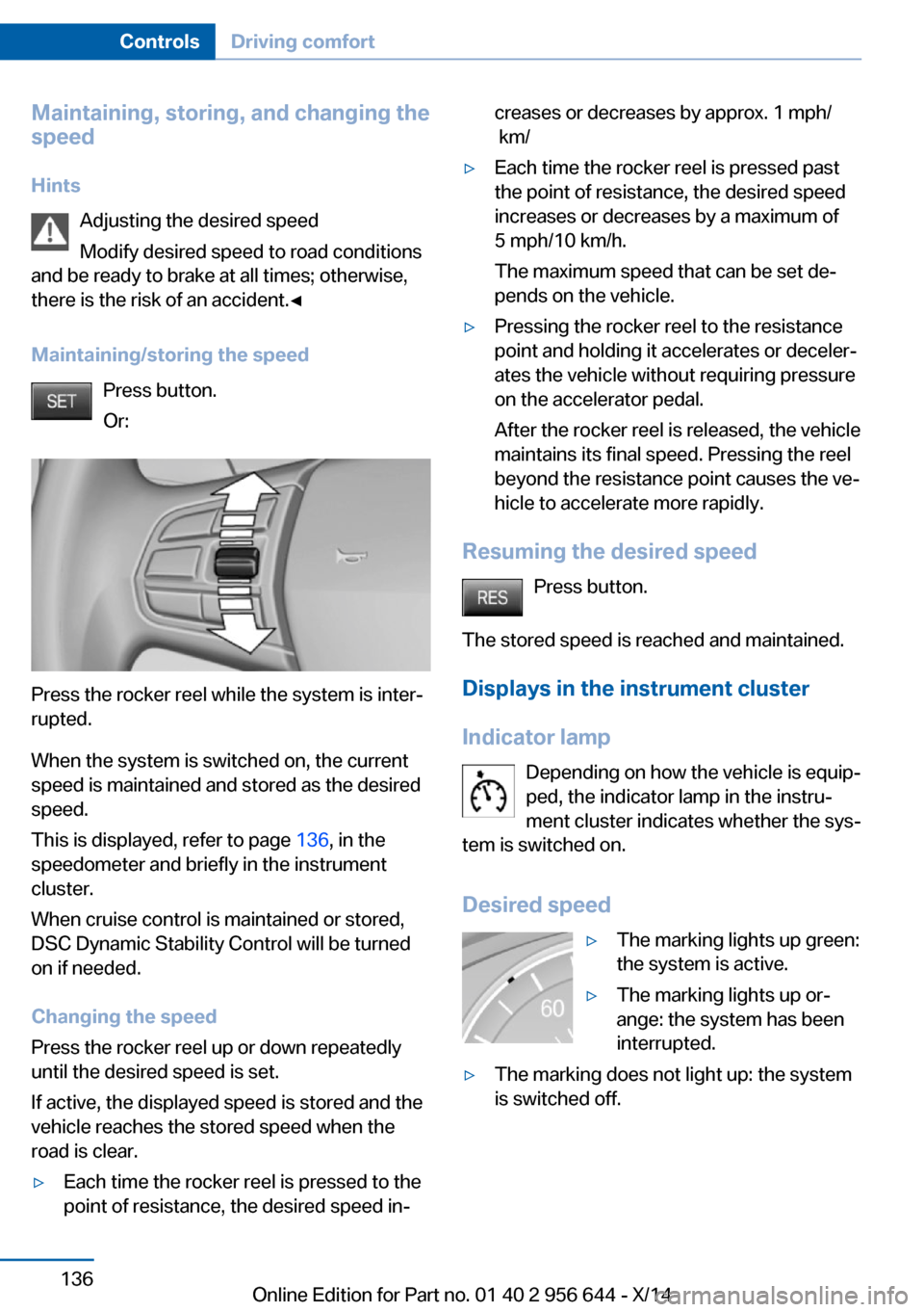
Maintaining/storing the speed Press button.
Or:
Press the rocker reel while the system is inter‐
rupted.
When the system is switched on, the current
speed is maintained and stored as the desired
speed.
This is displayed, refer to page 136, in the
speedometer and briefly in the instrument
cluster.
When cruise control is maintained or stored,
DSC Dynamic Stability Control will be turned
on if needed.
Changing the speed
Press the rocker reel up or down repeatedly
until the desired speed is set.
If active, the displayed speed is stored and the
vehicle reaches the stored speed when the
road is clear.
▷Each time the rocker reel is pressed to the
point of resistance, the desired speed in‐creases or decreases by approx. 1 mph/
km/▷Each time the rocker reel is pressed past
the point of resistance, the desired speed
increases or decreases by a maximum of
5 mph/10 km/h.
The maximum speed that can be set de‐
pends on the vehicle.▷Pressing the rocker reel to the resistance
point and holding it accelerates or deceler‐
ates the vehicle without requiring pressure
on the accelerator pedal.
After the rocker reel is released, the vehicle
maintains its final speed. Pressing the reel
beyond the resistance point causes the ve‐
hicle to accelerate more rapidly.
Resuming the desired speed
Press button.
The stored speed is reached and maintained. Displays in the instrument cluster
Indicator lamp Depending on how the vehicle is equip‐
ped, the indicator lamp in the instru‐
ment cluster indicates whether the sys‐
tem is switched on.
Desired speed
▷The marking lights up green:
the system is active.▷The marking lights up or‐
ange: the system has been
interrupted.▷The marking does not light up: the system
is switched off.Seite 136ControlsDriving comfort136
Online Edition for Part no. 01 40 2 956 644 - X/14
Page 221 of 251
Tail lights, bulb replacement
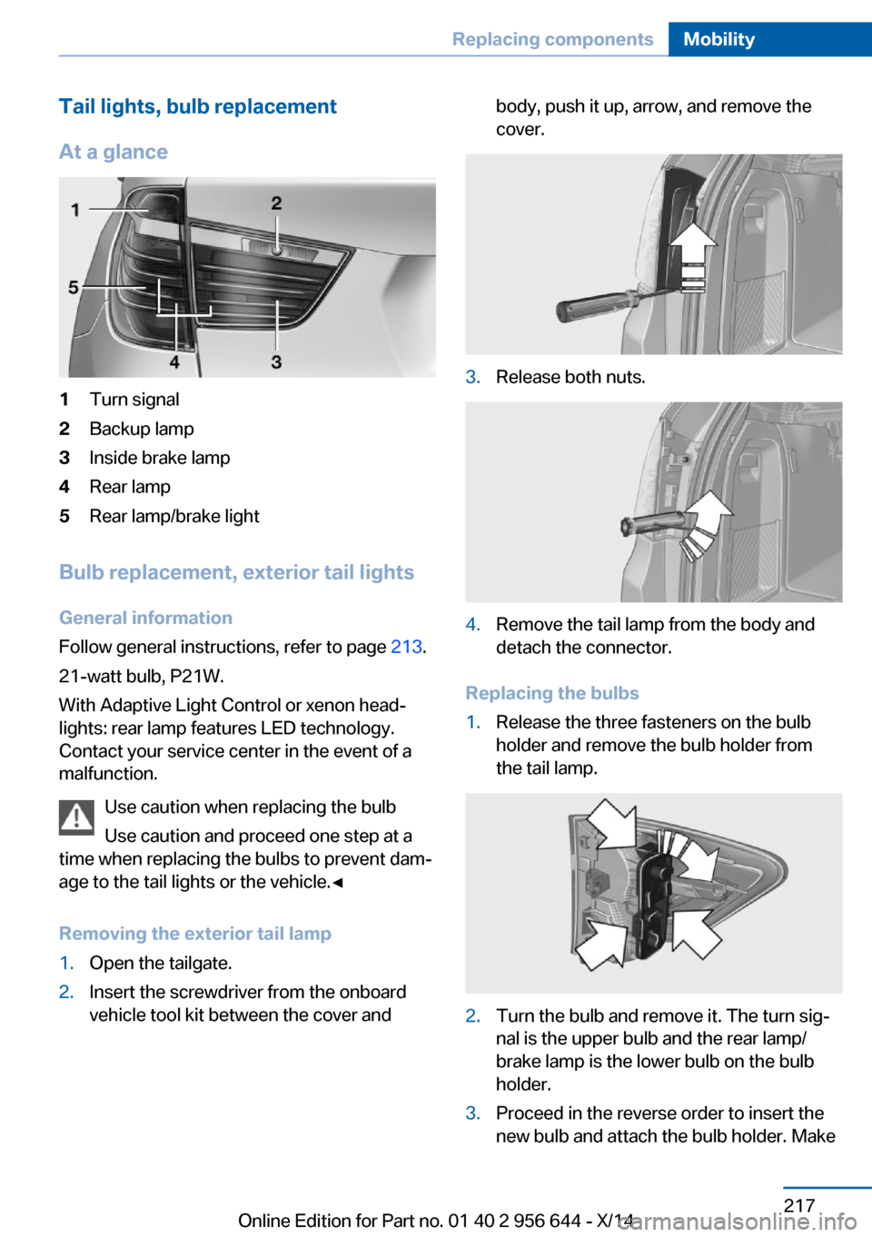
At a glance1Turn signal2Backup lamp3Inside brake lamp4Rear lamp5Rear lamp/brake light
Bulb replacement, exterior tail lights General information
Follow general instructions, refer to page 213.
21-watt bulb, P21W.
With Adaptive Light Control or xenon head‐
lights: rear lamp features LED technology.
Contact your service center in the event of a
malfunction.
Use caution when replacing the bulb
Use caution and proceed one step at a
time when replacing the bulbs to prevent dam‐
age to the tail lights or the vehicle.◀
Removing the exterior tail lamp
1.Open the tailgate.2.Insert the screwdriver from the onboard
vehicle tool kit between the cover andbody, push it up, arrow, and remove the
cover.3.Release both nuts.4.Remove the tail lamp from the body and
detach the connector.
Replacing the bulbs
1.Release the three fasteners on the bulb
holder and remove the bulb holder from
the tail lamp.2.Turn the bulb and remove it. The turn sig‐
nal is the upper bulb and the rear lamp/
brake lamp is the lower bulb on the bulb
holder.3.Proceed in the reverse order to insert the
new bulb and attach the bulb holder. MakeSeite 217Replacing componentsMobility217
Online Edition for Part no. 01 40 2 956 644 - X/14
Page 222 of 251
sure that the bulb holder is engaged in all
fasteners.
Installing the tail lamp
1.Connect and install the tail lamp.2.Insert the cover with the three mountings
in the tail lamp. While applying pressure on
the top and bottom bracket, slide the cover
down to the stop.
Lights in the tailgate
General information
Follow general instructions, refer to page 213.
Reversing lights: 16-watt bulb, W16W.
Inner brake lamp: 21-watt bulb, H21W.
Accessing the lights
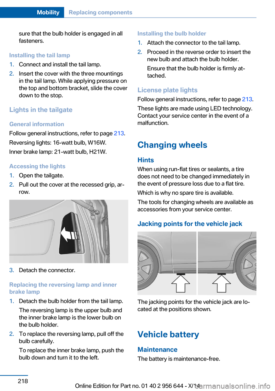
1.Open the tailgate.2.Pull out the cover at the recessed grip, ar‐
row.3.Detach the connector.
Replacing the reversing lamp and inner
brake lamp
1.Detach the bulb holder from the tail lamp.
The reversing lamp is the upper bulb and
the inner brake lamp is the lower bulb on
the bulb holder.2.To replace the reversing lamp, pull off the
bulb carefully.
To replace the inner brake lamp, push the
bulb down and turn it to the left.Installing the bulb holder1.Attach the connector to the tail lamp.2.Proceed in the reverse order to insert the
new bulb and attach the bulb holder.
Ensure that the bulb holder is firmly at‐
tached.
License plate lights
Follow general instructions, refer to page 213.
These lights are made using LED technology.
Contact your service center in the event of a
malfunction.
Changing wheels
Hints
When using run-flat tires or sealants, a tire
does not need to be changed immediately in
the event of pressure loss due to a flat tire.
Which is why no spare tire is available.
The tools for changing wheels are available as
accessories from your service center.
Jacking points for the vehicle jack
The jacking points for the vehicle jack are lo‐
cated at the positions shown.
Vehicle battery Maintenance
The battery is maintenance-free.
Seite 218MobilityReplacing components218
Online Edition for Part no. 01 40 2 956 644 - X/14
Page 232 of 251
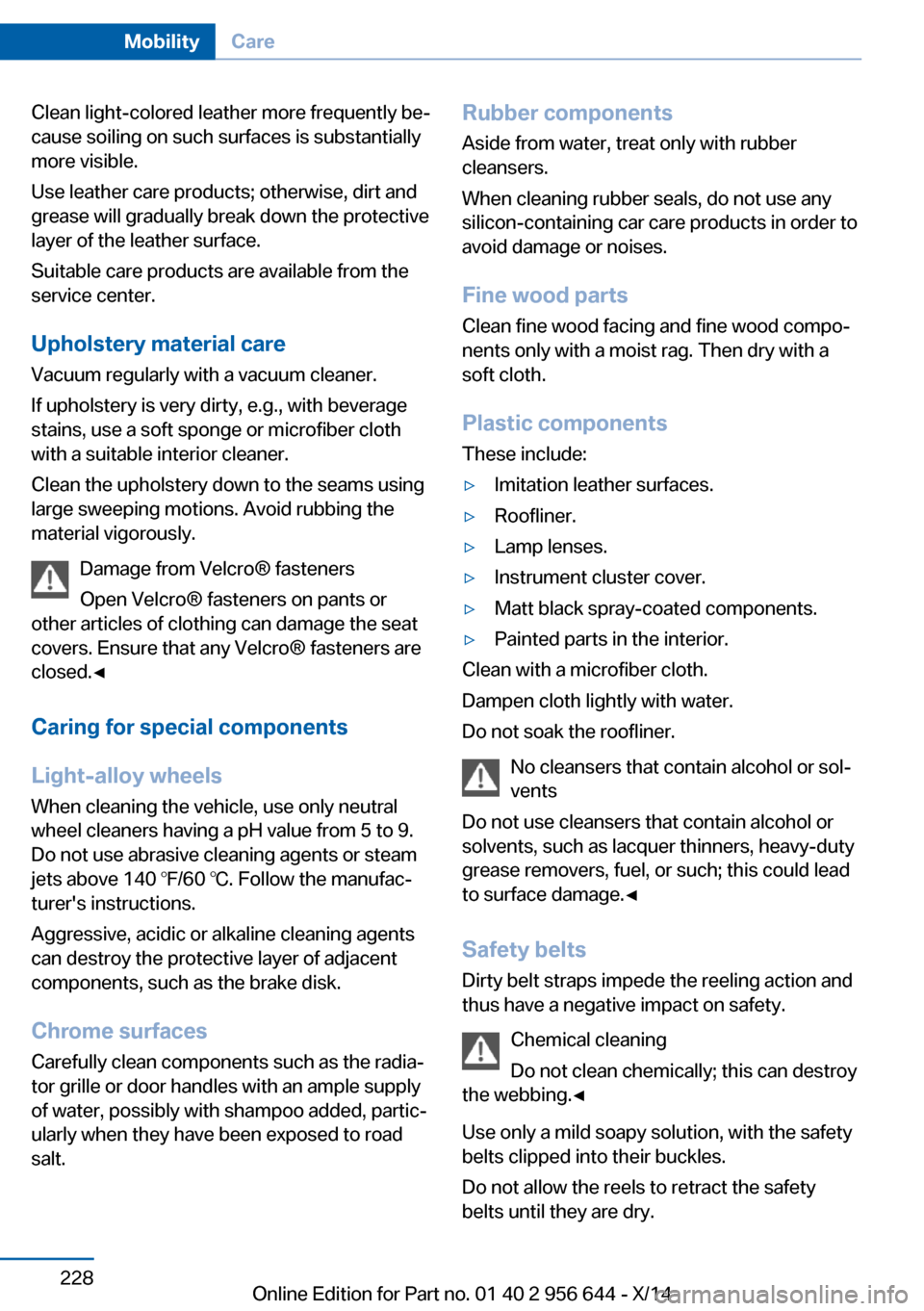
Clean light-colored leather more frequently be‐
cause soiling on such surfaces is substantially
more visible.
Use leather care products; otherwise, dirt and
grease will gradually break down the protective
layer of the leather surface.
Suitable care products are available from the
service center.
Upholstery material care Vacuum regularly with a vacuum cleaner.
If upholstery is very dirty, e.g., with beverage
stains, use a soft sponge or microfiber cloth
with a suitable interior cleaner.
Clean the upholstery down to the seams using
large sweeping motions. Avoid rubbing the
material vigorously.
Damage from Velcro® fasteners
Open Velcro® fasteners on pants or
other articles of clothing can damage the seat
covers. Ensure that any Velcro® fasteners are
closed.◀
Caring for special components
Light-alloy wheels When cleaning the vehicle, use only neutral
wheel cleaners having a pH value from 5 to 9.
Do not use abrasive cleaning agents or steam
jets above 140 ℉/60 ℃. Follow the manufac‐
turer's instructions.
Aggressive, acidic or alkaline cleaning agents
can destroy the protective layer of adjacent
components, such as the brake disk.
Chrome surfaces Carefully clean components such as the radia‐
tor grille or door handles with an ample supply of water, possibly with shampoo added, partic‐
ularly when they have been exposed to road
salt.Rubber components
Aside from water, treat only with rubber
cleansers.
When cleaning rubber seals, do not use any
silicon-containing car care products in order to
avoid damage or noises.
Fine wood partsClean fine wood facing and fine wood compo‐
nents only with a moist rag. Then dry with a
soft cloth.
Plastic components
These include:▷Imitation leather surfaces.▷Roofliner.▷Lamp lenses.▷Instrument cluster cover.▷Matt black spray-coated components.▷Painted parts in the interior.
Clean with a microfiber cloth.
Dampen cloth lightly with water.
Do not soak the roofliner.
No cleansers that contain alcohol or sol‐
vents
Do not use cleansers that contain alcohol or
solvents, such as lacquer thinners, heavy-duty
grease removers, fuel, or such; this could lead
to surface damage.◀
Safety belts
Dirty belt straps impede the reeling action and
thus have a negative impact on safety.
Chemical cleaning
Do not clean chemically; this can destroy
the webbing.◀
Use only a mild soapy solution, with the safety
belts clipped into their buckles.
Do not allow the reels to retract the safety
belts until they are dry.
Seite 228MobilityCare228
Online Edition for Part no. 01 40 2 956 644 - X/14
Page 243 of 251
Engine oil change 207
Engine oil filler neck 206
Engine oil temperature 84
Engine oil types, alterna‐ tive 207
Engine oil types, ap‐ proved 207
Engine start during malfunc‐ tion 35
Engine start, jump-start‐ ing 222
Engine start, refer to Starting the engine 66
Engine stop 66
Engine temperature 84
Entering a car wash 226
Equipment, interior 158
Error displays, see Check Control 80
ESP Electronic Stability Pro‐ gram, refer to DSC 121
Exchanging wheels/tires 200
Exhaust system 173
Exterior mirror, automatic dimming feature 59
Exterior mirrors 58
External start 222
External temperature dis‐ play 84
External temperature warn‐ ing 84
Eyes for securing cargo 177
F
Failure message, see Check Control 80
False alarm, refer to Uninten‐ tional alarm 47
Fan, refer to Air flow 151, 154
Filler neck for engine oil 206
Fine wood, care 228
First aid kit 222
Fitting for towing, see tow fit‐ ting 225 Flat tire, changing
wheels 218
Flat Tire Monitor FTM 105
Flat tire, Tire Pressure Moni‐ tor TPM 102
Flat tire, warning lamp 103, 106
Flooding 174
Floor carpet, care 229
Floor mats, care 229
Fold-out position, wiper 74
Foot brake 174
Front airbags 99
Front-end collision warning with braking function 111
Front-end collision warning with City Braking func‐
tion 108
Front fog lights 97
Front fog lights, bulb replace‐ ment 216
Front fog lights, front, bulb re‐ placement 215
Front lights 214
front-seat passenger airbags, automatic deactivation 101
Front-seat passenger airbags, indicator lamp 101
FTM Flat Tire Monitor 105
Fuel 190
Fuel consumption, current 85
Fuel consumption, refer to Average fuel consump‐
tion 89
Fuel filler flap 188
Fuel gauge 83
Fuel lid 188
Fuel quality 190
Fuel recommendation 190
Fuel, tank capacity 234
Fuse 219 G
Garage door opener, refer to Universal Integrated Remote
Control 158
Gasoline 190
Gear change, Steptronic transmission 75
Gear shift indicator 86
General driving notes 173
Glare shield 160
Glass sunroof, refer to Panor‐ amic glass sunroof 48
Glove compartment 166
Gross vehicle weight, ap‐ proved 233
H
Halogen headlights, bulb re‐ placement 214
Handbrake, refer to Parking brake 69
Hand-held transmitter, alter‐ nating code 159
Hazard warning flashers 221
HDC Hill Descent Con‐ trol 123
Head airbags 99
Headlight control, auto‐ matic 95
Headlight courtesy delay fea‐ ture 95
Headlight courtesy delay fea‐ ture via remote control 38
Headlight flasher 72
Headlight flasher, bulb re‐ placement 214
Headlight glass 213
Headlights 214
Headlights, care 227
Headlight washer system 72
Head restraints 51
Head restraints, front 55
Head restraints, rear 56
Head-up Display 92 Seite 239Everything from A to ZReference239
Online Edition for Part no. 01 40 2 956 644 - X/14