BMW X3 2015 F25 Owner's Manual
Manufacturer: BMW, Model Year: 2015, Model line: X3, Model: BMW X3 2015 F25Pages: 257, PDF Size: 5.26 MB
Page 121 of 257
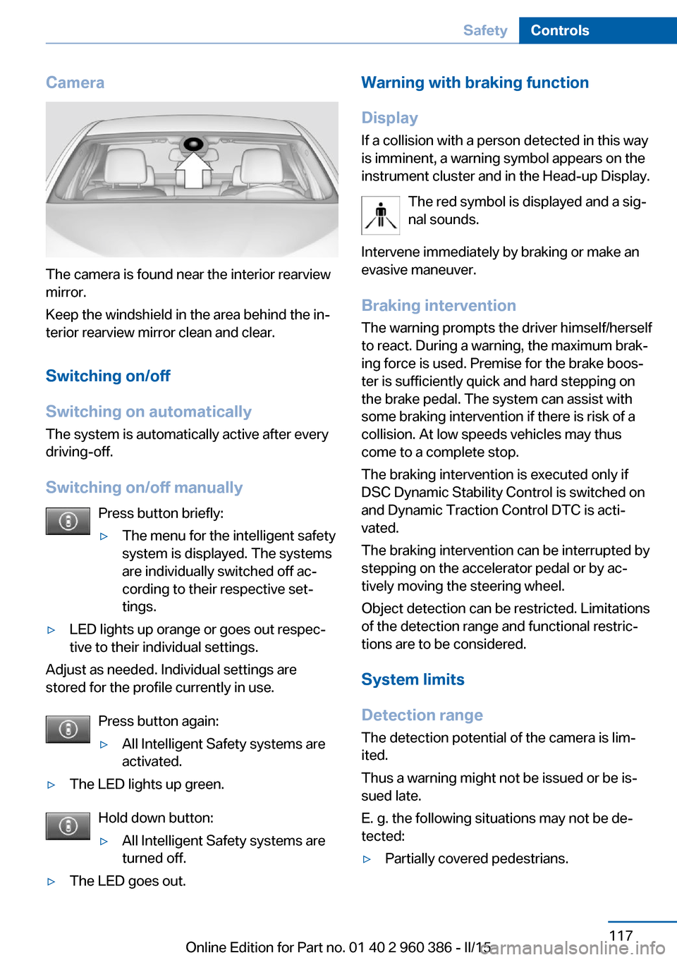
Camera
The camera is found near the interior rearview
mirror.
Keep the windshield in the area behind the in‐
terior rearview mirror clean and clear.
Switching on/off
Switching on automatically The system is automatically active after every
driving-off.
Switching on/off manually Press button briefly:
▷The menu for the intelligent safety
system is displayed. The systems
are individually switched off ac‐
cording to their respective set‐
tings.▷LED lights up orange or goes out respec‐
tive to their individual settings.
Adjust as needed. Individual settings are
stored for the profile currently in use.
Press button again:
▷All Intelligent Safety systems are
activated.▷The LED lights up green.
Hold down button:
▷All Intelligent Safety systems are
turned off.▷The LED goes out.Warning with braking function
Display
If a collision with a person detected in this way
is imminent, a warning symbol appears on the
instrument cluster and in the Head-up Display.
The red symbol is displayed and a sig‐
nal sounds.
Intervene immediately by braking or make an
evasive maneuver.
Braking intervention
The warning prompts the driver himself/herself
to react. During a warning, the maximum brak‐
ing force is used. Premise for the brake boos‐
ter is sufficiently quick and hard stepping on
the brake pedal. The system can assist with
some braking intervention if there is risk of a
collision. At low speeds vehicles may thus
come to a complete stop.
The braking intervention is executed only if
DSC Dynamic Stability Control is switched on
and Dynamic Traction Control DTC is acti‐
vated.
The braking intervention can be interrupted by
stepping on the accelerator pedal or by ac‐
tively moving the steering wheel.
Object detection can be restricted. Limitations
of the detection range and functional restric‐
tions are to be considered.
System limits
Detection range
The detection potential of the camera is lim‐
ited.
Thus a warning might not be issued or be is‐
sued late.
E. g. the following situations may not be de‐
tected:▷Partially covered pedestrians.Seite 117SafetyControls117
Online Edition for Part no. 01 40 2 960 386 - II/15
Page 122 of 257
▷Pedestrians that are not detected as such
because of the viewing angle or contour.▷Pedestrians outside of the detection range.▷Pedestrians having a body size less than
32 in/80 cm.
Functional limitations
The system may not be fully functional or may
not be available in the following situations:
▷In heavy fog, rain, sprayed water or snow‐
fall.▷In tight curves.▷If the driving stability control systems are
deactivated, e.g. DSC OFF.▷If the camera viewing field or the front
windshield are dirty or covered.▷Up to 10 seconds after the start of the en‐
gine, via the Start/Stop knob.▷During calibration of the camera immedi‐
ately after vehicle shipment.▷If there is constant blinding effects be‐
cause of oncoming light, e. g., from the sun
low in the sky.▷When it is dark outside.
Lane departure warning
The concept Starting at a specific speed, this system alerts
you when the vehicle on streets with lane
markings is about to leave the lane. This
speed, depending on the country version, is
between 35 mph/55 km/h and
45 mph/70 km/h.
The steering wheel begins vibrating gently in
the event of warnings. The time of the warning
may vary depending on the current driving sit‐
uation.
The system does not provide a warning if the
turn signal is set before leaving the lane.
Hints
Personal responsibility
The system cannot serve as a substitute
for the driver's personal judgment of the
course of the road and the traffic situation.
In the event of a warning, do not jerk the steer‐
ing wheel, as you may lose control of the vehi‐
cle.◀
At a glance
Button in the vehicle
Intelligent Safety button
Camera
The camera is found near the interior rearview
mirror.
Keep the windshield in the area behind the in‐
terior rearview mirror clean and clear.
Seite 118ControlsSafety118
Online Edition for Part no. 01 40 2 960 386 - II/15
Page 123 of 257
Switching on/off
Switching on automatically The lane departure warning is automatically
activated after departure, if the function was
switched on the last time the engine was stop‐
ped.
Switching on/off manually Press button briefly:▷The menu for the intelligent safety
system is displayed. The systems
are individually switched off ac‐
cording to their respective set‐
tings.▷LED lights up orange or goes out respec‐
tive to their individual settings.
Adjust as needed. Individual settings are
stored for the profile currently in use.
Press button again:
▷All Intelligent Safety systems are
activated.▷The LED lights up green.
Hold down button:
▷All Intelligent Safety systems are
turned off.▷The LED goes out.
Display in the instrument cluster
▷Lines: system is activated.▷Arrows: at least one lane marking
was detected and warnings can be
issued.
Issued warning
If you leave the lane and if a lane marking has
been detected, the steering wheel begins vi‐
brating.
If the turn signal is set before changing the
lane, a warning is not issued.
End of warning
The warning ends:▷Automatically after approx. 3 seconds.▷When returning to your own lane.▷When braking hard.▷When using the turn signal.
System limits
The system may not be fully functional in the
following situations:
▷In heavy fog, rain or snowfall.▷In the event of missing, worn, poorly visi‐
ble, merging, diverging, or multiple lane
markings such as in construction areas.▷When lane markings are covered in snow,
ice, dirt or water.▷In tight curves or on narrow lanes.▷When the lane markings are covered by
objects.▷When driving very close to the vehicle in
front of you.▷When driving toward bright lights.▷When the windshield in front of the interior
rearview mirror is fogged over, dirty or cov‐
ered with stickers, etc.▷During calibration of the camera immedi‐
ately after vehicle shipment.Seite 119SafetyControls119
Online Edition for Part no. 01 40 2 960 386 - II/15
Page 124 of 257
Active Blind Spot Detection
The concept
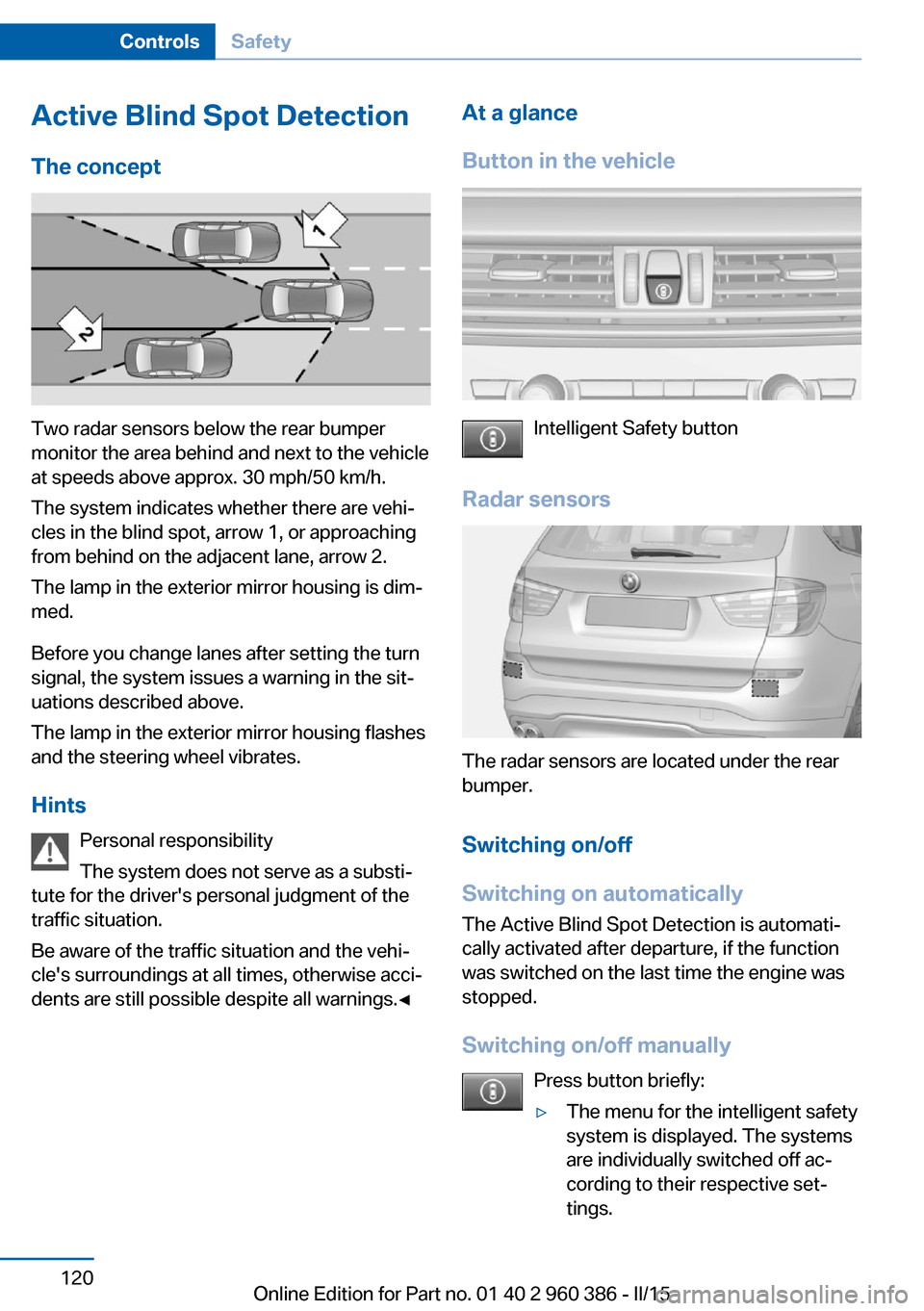
Two radar sensors below the rear bumper
monitor the area behind and next to the vehicle
at speeds above approx. 30 mph/50 km/h.
The system indicates whether there are vehi‐
cles in the blind spot, arrow 1, or approaching
from behind on the adjacent lane, arrow 2.
The lamp in the exterior mirror housing is dim‐
med.
Before you change lanes after setting the turn
signal, the system issues a warning in the sit‐
uations described above.
The lamp in the exterior mirror housing flashes
and the steering wheel vibrates.
Hints Personal responsibility
The system does not serve as a substi‐
tute for the driver's personal judgment of the
traffic situation.
Be aware of the traffic situation and the vehi‐
cle's surroundings at all times, otherwise acci‐
dents are still possible despite all warnings.◀
At a glance
Button in the vehicle
Intelligent Safety button
Radar sensors
The radar sensors are located under the rear
bumper.
Switching on/off
Switching on automatically The Active Blind Spot Detection is automati‐
cally activated after departure, if the function
was switched on the last time the engine was
stopped.
Switching on/off manually Press button briefly:
▷The menu for the intelligent safety
system is displayed. The systems
are individually switched off ac‐
cording to their respective set‐
tings.Seite 120ControlsSafety120
Online Edition for Part no. 01 40 2 960 386 - II/15
Page 125 of 257
▷LED lights up orange or goes out respec‐
tive to their individual settings.
Adjust as needed. Individual settings are
stored for the profile currently in use.
Press button again:
▷All Intelligent Safety systems are
activated.▷The LED lights up green.
Hold down button:
▷All Intelligent Safety systems are
turned off.▷The LED goes out.
Display
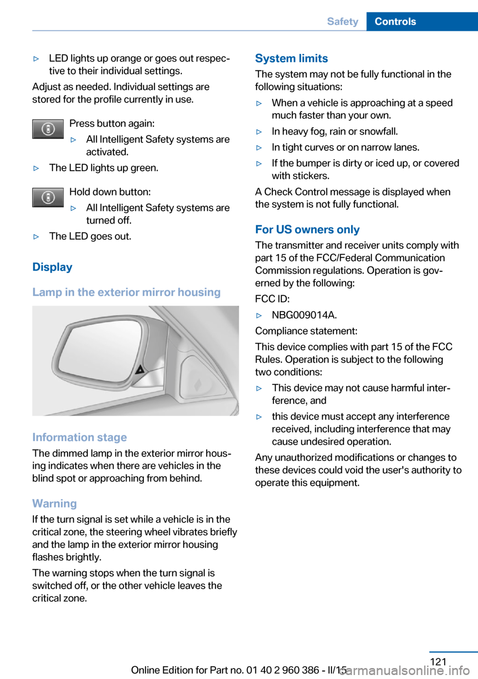
Lamp in the exterior mirror housing
Information stage
The dimmed lamp in the exterior mirror hous‐
ing indicates when there are vehicles in the
blind spot or approaching from behind.
Warning If the turn signal is set while a vehicle is in the
critical zone, the steering wheel vibrates briefly
and the lamp in the exterior mirror housing
flashes brightly.
The warning stops when the turn signal is
switched off, or the other vehicle leaves the
critical zone.
System limits
The system may not be fully functional in the
following situations:▷When a vehicle is approaching at a speed
much faster than your own.▷In heavy fog, rain or snowfall.▷In tight curves or on narrow lanes.▷If the bumper is dirty or iced up, or covered
with stickers.
A Check Control message is displayed when
the system is not fully functional.
For US owners only The transmitter and receiver units comply with
part 15 of the FCC/Federal Communication
Commission regulations. Operation is gov‐
erned by the following:
FCC ID:
▷NBG009014A.
Compliance statement:
This device complies with part 15 of the FCC
Rules. Operation is subject to the following
two conditions:
▷This device may not cause harmful inter‐
ference, and▷this device must accept any interference
received, including interference that may
cause undesired operation.
Any unauthorized modifications or changes to
these devices could void the user's authority to
operate this equipment.
Seite 121SafetyControls121
Online Edition for Part no. 01 40 2 960 386 - II/15
Page 126 of 257
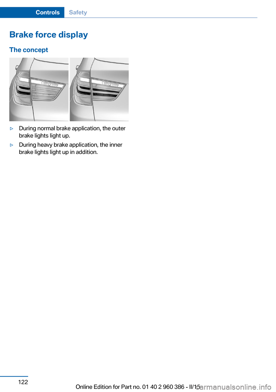
Brake force display
The concept▷During normal brake application, the outer
brake lights light up.▷During heavy brake application, the inner
brake lights light up in addition.Seite 122ControlsSafety122
Online Edition for Part no. 01 40 2 960 386 - II/15
Page 127 of 257
Driving stability control systemsVehicle features and optionsThis chapter describes all standard, country-
specific and optional features offered with the
series. It also describes features that are not
necessarily available in your car, e. g., due to
the selected options or country versions. This
also applies to safety-related functions and
systems. The respectively applicable country
provisions must be observed when using the
respective features and systems.
Antilock Brake System ABS ABS prevents locking of the wheels during
braking.
The vehicle contains its steering power even
during full brake applications, thus increasing
active safety.
ABS is operational every time you start the en‐
gine.
Brake assistant When you apply the brakes rapidly, this system
automatically produces the greatest possible
braking force boost. It reduces the braking dis‐
tance to a minimum during emergency stop.
This system utilizes all of the benefits provided
by ABS.
Do not reduce the pressure on the brake pedal
for the duration of the emergency stop.
DSC Dynamic Stability
Control
The concept DSC prevents traction loss in the power
wheels when driving off and accelerating.DSC also recognizes unstable vehicle condi‐
tions such as fishtailing or nose-diving. Within
the physical limits DSC helps to keep the vehi‐
cle on a steady course by reducing engine
speed and by applying brakes to the individual
wheels.
Note Adjust your driving style to the situation
An appropriate driving style is always the
responsibility of the driver.
The laws of physics cannot be repealed, not
even with DSC.
Therefore, do not reduce the additional safety
margin by driving in a risky manner.◀
Do not deactivate DSC when driving with
roof load
Do not deactivate Dynamic Stability Control DSC when driving with roof load, e.g. roof-
mounted luggage rack.
Otherwise, driving safety is not given in driv‐
ing-critical situation due to the elevated center
of gravity.◀
Overview
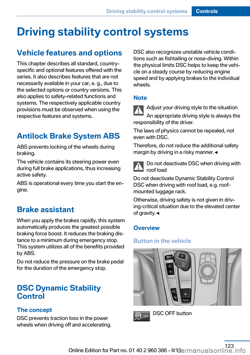
Button in the vehicle
DSC OFF button
Seite 123Driving stability control systemsControls123
Online Edition for Part no. 01 40 2 960 386 - II/15
Page 128 of 257
Indicator/warning lightsThe indicator lamp flashes: DSC con‐
trols the drive and braking forces.
The indicator lamp lights up: DSC has
failed.
Deactivating DSC: DSC OFF When DSC is deactivated, driving stability is
reduced during acceleration and when driving
in curves.
To increase vehicle stability, activate DSC
again as soon as possible.
Deactivating DSC Press and hold this button but not lon‐
ger than approx. 10 seconds, until the
indicator lamp for DSC OFF lights up in the in‐
strument cluster and displays DSC OFF.
The DSC system is switched off.
The steering and, depending on the equip‐
ment, suspension are tuned for sporty driving.
Activating DSC Press button.
DSC OFF and the DSC OFF indicator
lamp go out.
Indicator/warning lights
When DSC is deactivated, DSC OFF is dis‐
played in the instrument cluster.
The indicator lamp lights up: DSC is
deactivated.
DTC Dynamic Traction
Control
The concept
The DTC system is a version of the DSC where
forward momentum is optimized.The system ensures maximum headway on
special road conditions or loose road surfaces,
e.g., unplowed snowy roads, but with some‐
what limited driving stability.
Activating the Dynamic Traction Control DTC
provides maximum traction. Driving stability is
limited during acceleration and when driving in
curves.
Therefore drive with appropriate caution.
You may find it useful to briefly activate DTC
under the following special circumstances:▷When driving in slush or on uncleared,
snow-covered roads.▷When freeing vehicle from deep snow or
driving off from loose grounds.▷When driving with snow chains.
Deactivating/activating DTC Dynamic
Traction Control
Activating DTC Press button.
TRACTION is displayed in the instru‐
ment cluster and the indicator lamp for DSC
OFF lights up.
Deactivating DTC Press button again.
TRACTION and the DSC OFF indica‐
tor lamp go out.
Performance Control Performance Control enhances the agility of
the vehicle.
To increase maneuverability, with a corre‐
spondingly sporty driving style, wheels are
braked individually. The resulting braking
power is simultaneously largely compensated
by an engine intervention.
Seite 124ControlsDriving stability control systems124
Online Edition for Part no. 01 40 2 960 386 - II/15
Page 129 of 257
xDrivexDrive is the all-wheel-drive system of your ve‐
hicle. Concerted action by the xDrive and DSC
further optimize traction and driving dynamics.
The xDrive all-wheel-drive system variably dis‐
tributes the drive forces to the front and rear
axles as demanded by the driving situation and
road surface.
Display on the Control Display
Displaying xDrive view1."Vehicle info"2."xDrive status"
The following information is displayed:
▷With a navigation system: compass display
for the driving direction▷Pitch attitude with degree and percentage▷Transverse gradient with degree indication▷Graphic display for the steering
HDC Hill Descent Control
The concept HDC is a downhill driving assistant that auto‐
matically controls vehicle speed on steep
downhill gradients. Without applying the
brakes, the vehicle moves at slightly more than
walking speed.
Hill Descent Control can be activated at
speeds below approx. 22 mph/35 km/h. When
driving downhill, the vehicle reduces its speed
to approx. walking speed and then keeps its
speed constant.
As long as there is active braking, the system
is on standby. The system does not brake the
vehicle during this time.
Only use HDC in low gears or in selector lever
position D or R.
Increasing or decreasing vehicle
speed
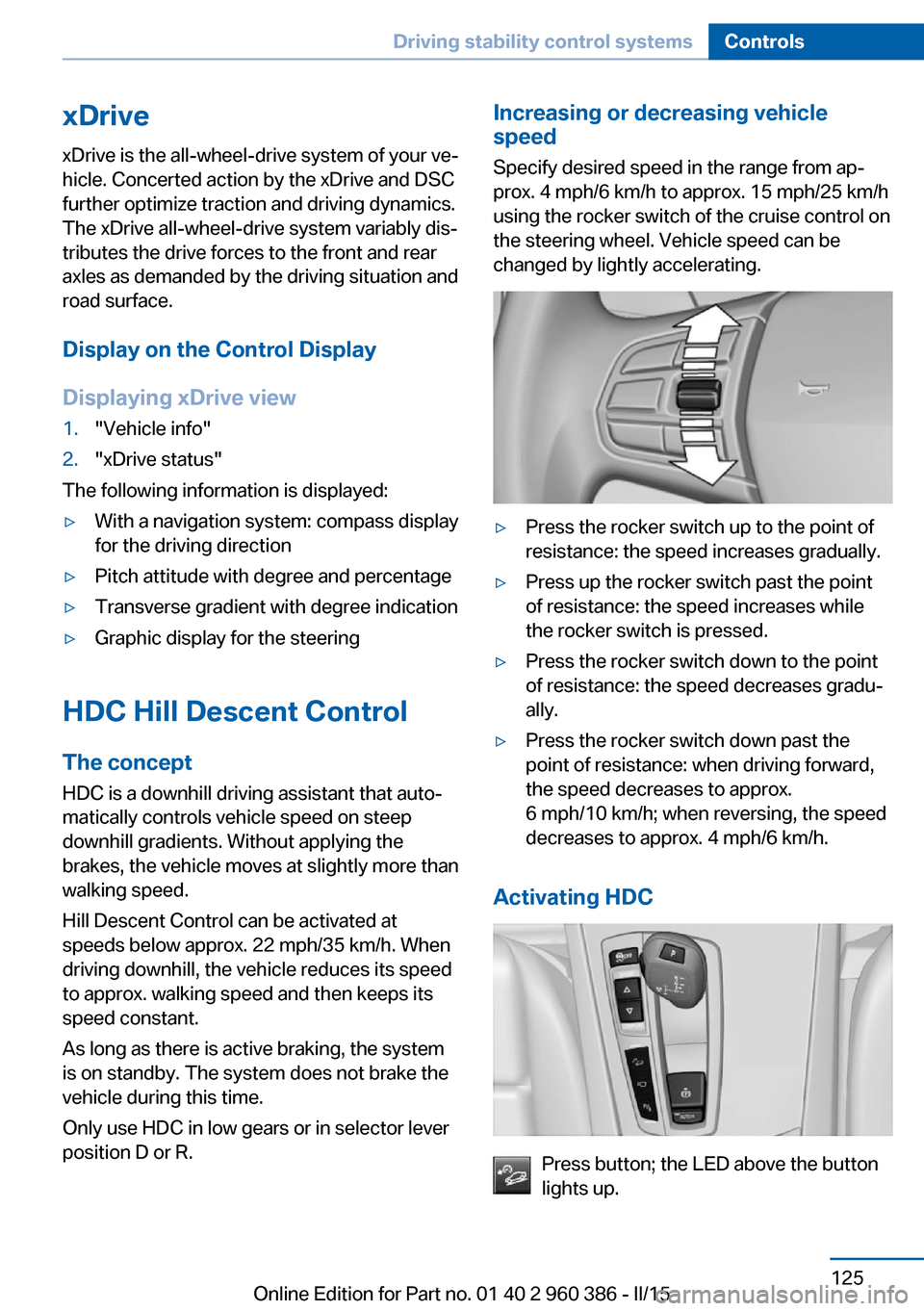
Specify desired speed in the range from ap‐
prox. 4 mph/6 km/h to approx. 15 mph/25 km/h
using the rocker switch of the cruise control on
the steering wheel. Vehicle speed can be
changed by lightly accelerating.▷Press the rocker switch up to the point of
resistance: the speed increases gradually.▷Press up the rocker switch past the point
of resistance: the speed increases while
the rocker switch is pressed.▷Press the rocker switch down to the point
of resistance: the speed decreases gradu‐
ally.▷Press the rocker switch down past the
point of resistance: when driving forward,
the speed decreases to approx.
6 mph/10 km/h; when reversing, the speed
decreases to approx. 4 mph/6 km/h.
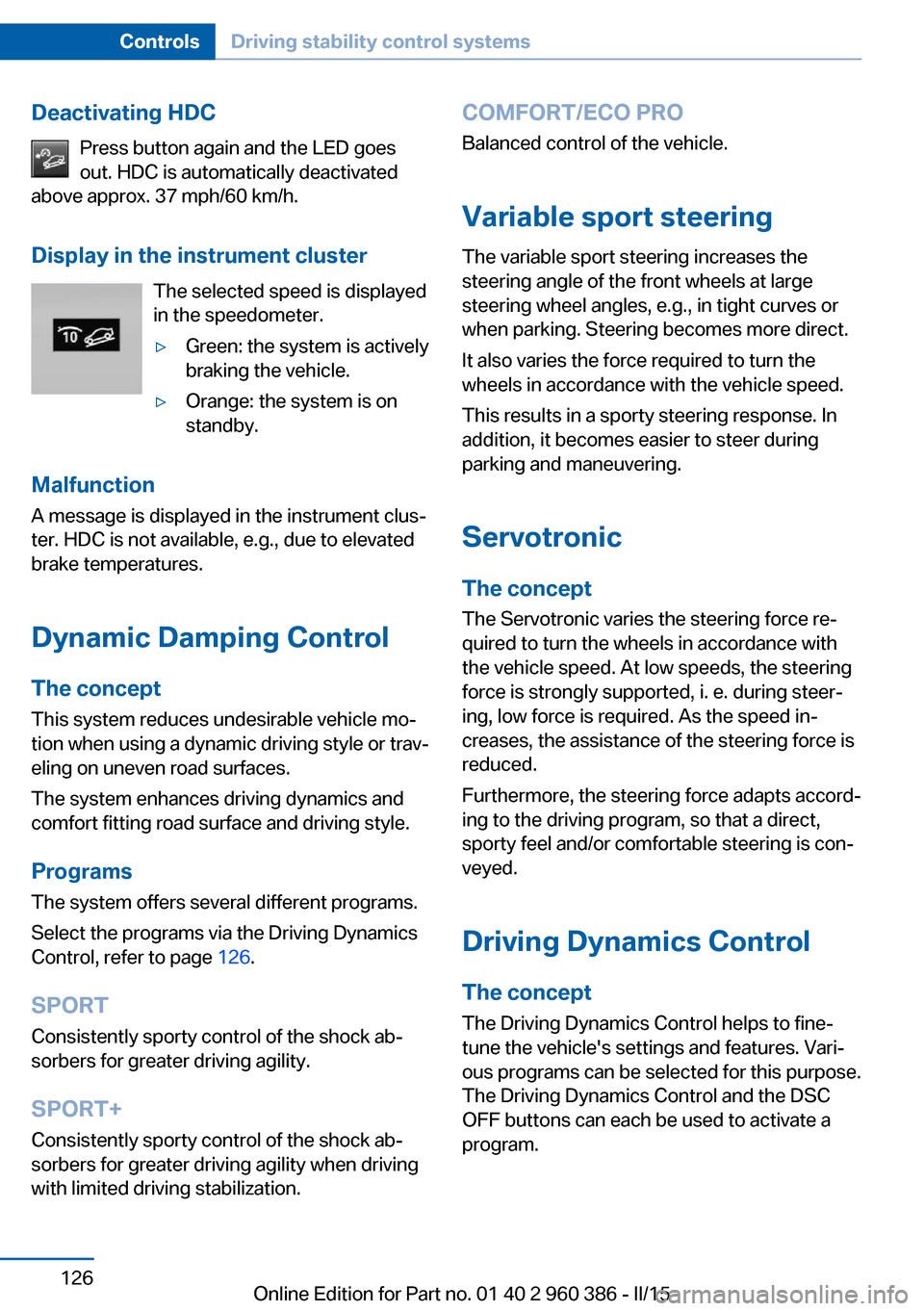
Activating HDC
Press button; the LED above the button
lights up.
Seite 125Driving stability control systemsControls125
Online Edition for Part no. 01 40 2 960 386 - II/15
Page 130 of 257
Deactivating HDCPress button again and the LED goes
out. HDC is automatically deactivated
above approx. 37 mph/60 km/h.
Display in the instrument cluster The selected speed is displayed
in the speedometer.▷Green: the system is actively
braking the vehicle.▷Orange: the system is on
standby.
Malfunction
A message is displayed in the instrument clus‐
ter. HDC is not available, e.g., due to elevated
brake temperatures.
Dynamic Damping Control
The concept This system reduces undesirable vehicle mo‐
tion when using a dynamic driving style or trav‐
eling on uneven road surfaces.
The system enhances driving dynamics and
comfort fitting road surface and driving style.
Programs The system offers several different programs.
Select the programs via the Driving Dynamics
Control, refer to page 126.
SPORT Consistently sporty control of the shock ab‐
sorbers for greater driving agility.
SPORT+ Consistently sporty control of the shock ab‐
sorbers for greater driving agility when driving
with limited driving stabilization.
COMFORT/ECO PRO
Balanced control of the vehicle.
Variable sport steering The variable sport steering increases the
steering angle of the front wheels at large
steering wheel angles, e.g., in tight curves or
when parking. Steering becomes more direct.
It also varies the force required to turn the
wheels in accordance with the vehicle speed.
This results in a sporty steering response. In
addition, it becomes easier to steer during
parking and maneuvering.
Servotronic The conceptThe Servotronic varies the steering force re‐
quired to turn the wheels in accordance with
the vehicle speed. At low speeds, the steering
force is strongly supported, i. e. during steer‐
ing, low force is required. As the speed in‐ creases, the assistance of the steering force is
reduced.
Furthermore, the steering force adapts accord‐
ing to the driving program, so that a direct, sporty feel and/or comfortable steering is con‐
veyed.
Driving Dynamics Control
The concept The Driving Dynamics Control helps to fine-
tune the vehicle's settings and features. Vari‐
ous programs can be selected for this purpose.
The Driving Dynamics Control and the DSC
OFF buttons can each be used to activate a
program.Seite 126ControlsDriving stability control systems126
Online Edition for Part no. 01 40 2 960 386 - II/15