ECO mode BMW X3 2017 Owners Manual
[x] Cancel search | Manufacturer: BMW, Model Year: 2017, Model line: X3, Model: BMW X3 2017Pages: 265, PDF Size: 5.37 MB
Page 7 of 265
Enumerations
Enumerations without mandatory order or al‐
ternative possibilities are presented as list with
bullet points.▷First possibility.▷Second possibility.
Symbols on vehicle components
Indicates that you should consult the
relevant section of this Owner's Manual for
information on a particular part or assembly.
Vehicle features and options
This Owner's Manual describes all models and
all standard, country-specific and optional
equipment that is offered in the model series.
Therefore, in this Owner's Manual, we also de‐
scribe and illustrate features that are not avail‐
able in your vehicle, for example, because of
the selected optional features or the country-
specific version.
This also applies to safety-related functions
and systems.
The respectively applicable country provisions
must be observed when using the respective
features and systems.
For any options and equipment not described
in this Owner's Manual, refer to the Supple‐
mentary Owner's Manuals.
On right-hand drive vehicles, some control ele‐ ments are arranged differently from what is
shown in the illustrations.
Status of the Owner's
Manual
Basic information
The manufacturer of your vehicle pursues a
policy of constant development that is con‐
ceived to ensure that our vehicles continue to
embody the highest quality and safety stand‐
ards. In rare cases, therefore, the features de‐
scribed in this Owner's Manual may differ from
those in your vehicle.
Updates made after the editorial
deadline
Due to updates after the editorial deadline, dif‐
ferences may exist between the printed Own‐
er's Manual and the following Owner's Man‐
uals:▷Integrated Owner's Manual in the vehicle.▷Online Owner's Manual.▷BMW Driver’s Guide app.
Notes on updates can be found in the appen‐
dix of the printed Owner's Manual for the vehi‐
cle.
Own safety
Warranty
Your vehicle is technically configured for the
operating conditions and registration require‐
ments applying in the country of first delivery
also known as homologation. If your vehicle is
to be operated in a different country it might be
necessary to adapt your vehicle to potentially
differing operating conditions and permit re‐
quirements. If your vehicle does not comply
with the homologation requirements in a cer‐
tain country you may not be able to lodge war‐
ranty claims for your vehicle there. Further in‐
formation on warranty is available from a
dealer’s service center.
Maintenance and repairs
Advanced technology, e.g., the use of modern
materials and high-performance electronics,
requires suitable maintenance and repair work.
The manufacturer of the vehicle recommends
that you entrust corresponding procedures to
a BMW dealer’s service center. If you choose
to use another service facility, BMW recom‐
mends use of a facility that performs work, e.g.
Seite 7Information7
Online Edition for Part no. 01 40 2 969 976 - II/16
Page 8 of 265
maintenance and repair, according to BMW
specifications with properly trained personnel,
referred to in this Owner's Manual as "another
qualified service center or repair shop".
If work is performed improperly, e.g. mainte‐
nance and repair, there is a risk of subsequent
damage and related safety risks.
Parts and accessories
BMW recommends the use of parts and ac‐
cessory products approved by BMW.
Approved parts and accessories, and advice
on their use and installation are available from
a BMW dealer's service center.
BMW parts and accessories were tested by
BMW for their safety and suitability in BMW
vehicles.
BMW warrants genuine BMW parts and acces‐
sories.
BMW does not evaluate whether each individ‐
ual product from another manufacturer can be
used with BMW vehicles without presenting a
safety hazard, even if a country-specific official
approval was issued. BMW does not evaluate
whether these products are suitable for BMW
vehicles under all usage conditions.
California Proposition 65 Warning
California laws require us to state the following
warning:
Engine exhaust and a wide variety of automo‐ bile components and parts, including compo‐
nents found in the interior furnishings in a vehi‐
cle, contain or emit chemicals known to the State of California to cause cancer and birth
defects and reproductive harm. In addition,
certain fluids contained in vehicles and certain
products of component wear contain or emit
chemicals known to the State of California to
cause cancer and birth defects or other repro‐
ductive harm. Battery posts, terminals and re‐
lated accessories contain lead and lead com‐
pounds. Wash your hands after handling. Used
engine oil contains chemicals that have causedcancer in laboratory animals. Always protect
your skin by washing thoroughly with soap and
water.
Service and warranty
We recommend that you read this publication
thoroughly. Your vehicle is covered by the fol‐
lowing warranties:▷New Vehicle Limited Warranty.▷Rust Perforation Limited Warranty.▷Federal Emissions System Defect War‐
ranty.▷Federal Emissions Performance Warranty.▷California Emission Control System Lim‐
ited Warranty.
Detailed information about these warranties is
listed in the Service and Warranty Information
Booklet for US models or in the Warranty and
Service Guide Booklet for Canadian models.
Your vehicle has been specifically adapted and
designed to meet the particular operating con‐
ditions and homologation requirements in your
country and continental region in order to de‐
liver the full driving pleasure while the vehicle
is operated under those conditions. If you wish
to operate your vehicle in another country or
region, you may be required to adapt your ve‐
hicle to meet different prevailing operating
conditions and homologation requirements.
You should also be aware of any applicable
warranty limitations or exclusions for such
country or region. In such case, please contact
Customer Relations for further information.
Maintenance
Maintain the vehicle regularly to sustain the
road safety, operational reliability and the New
Vehicle Limited Warranty.
Specifications for required maintenance meas‐
ures:
▷BMW Maintenance system▷Service and Warranty Information Booklet
for US modelsSeite 8Information8
Online Edition for Part no. 01 40 2 969 976 - II/16
Page 9 of 265
▷Warranty and Service Guide Booklet for
Canadian models
If the vehicle is not maintained according to
these specifications, this could result in seri‐
ous damage to the vehicle. Such damage is
not covered by the BMW New Vehicle Limited
Warranty.
Data memory
Many electronic components on your vehicle
are equipped with data memories that tempo‐
rarily or permanently store technical informa‐
tion about the condition of the vehicle, events
and faults. This technical information generally
records the state of a component, a module, a system or the environment:
▷Operating mode of system components, fill
levels for instance.▷Status messages for the vehicle and from
its individual components, for example,
wheel rotation speed/vehicle speed, decel‐
eration, transverse acceleration.▷Malfunctions and faults in important sys‐
tem components, for example, lights and
brakes.▷Responses by the vehicle to special situa‐
tions such as airbag deployment or engag‐
ing the stability control system.▷Ambient conditions, such as temperature.
This data is purely technical in nature and is
used to detect and correct faults and to opti‐
mize vehicle functions. Motion profiles over
routes traveled cannot be created from this
data. When service offerings are used, for ex‐
ample, repair services, service processes, war‐
ranty claims, quality assurance, this technical
information can be read out from the event and
fault memories by employees of the dealer’s
service center or another qualified service cen‐
ter or repair shop, including the manufacturer,
using special diagnostic tools. You can obtain
further information there if you need it. After an
error is corrected, the information in the fault
memory is deleted or overwritten on a continu‐
ous basis.
With the vehicle in use there are situations
where you can associate these technical data
with individuals if combined with other infor‐
mation, for example, an accident report, dam‐
age to the vehicle, eye witness accounts —
possibly with the assistance of an expert.
Additional functions that are contractually
agreed with the customer - such as vehicle
emergency locating - you can transmit certain
vehicle data from the vehicle.
Event Data Recorder EDR
This vehicle is equipped with an event data re‐
corder EDR. The main purpose of an EDR is to
record, in certain crash or near crash-like situa‐
tions, such as an air bag deployment or hitting
a road obstacle, data that will assist in under‐
standing how a vehicle’s systems performed.
The EDR is designed to record data related to
vehicle dynamics and safety systems for a
short period of time, typically 30 seconds or
less.
The EDR in this vehicle is designed to record
such data as:▷How various systems in your vehicle were
operating.▷Whether or not the driver and passenger
safety belts were fastened.▷How far, if at all, the driver was depressing
the accelerator and/or brake pedal.▷How fast the vehicle was traveling.
These data can help provide a better under‐
standing of the circumstances in which
crashes and injuries occur.
EDR data are recorded by your vehicle only if a
nontrivial crash situation occurs; no data are
recorded by the EDR under normal driving
conditions and no personal data, e. g., name,
gender, age, and crash location, are recorded.
Seite 9Information9
Online Edition for Part no. 01 40 2 969 976 - II/16
Page 38 of 265
Using the remote control
Information WARNING
People or animals in the vehicle can lock
the doors from the inside and lock themselves
in. The vehicle can then not be opened from
the outside. There is a risk of injury. Take the
remote control along so that the vehicle can be
opened from the outside.◀
Unlocking Press button on the remote control.
Depending on the settings, refer to page 46,
the following access points are unlocked.▷Driver's door and fuel filler flap.▷All doors, tailgate, and fuel filler flap.
In addition, the following functions are exe‐
cuted:
▷The interior lights are switched on, when it
is dark outside, the courtesy lamps are also
switched on. This function is not available,
if the interior lamps were switched off man‐
ually.▷The welcome lamps are switched on, if this
function was activated.▷The alarm system, refer to page 47, is
switched off.
Convenient opening
Press and hold this button on the re‐
mote control after unlocking.
The windows and the glass sunroof are
opened, as long as the button on the remote
control is pressed.
Locking WARNING
Unlocking from the inside is only possi‐
ble with special knowledge.
If people must spend a longer time in the vehi‐
cle while it is very hot or cold outside, there is a
risk of injuries or danger to life. Do not lock the
vehicle from the outside when there are people
in it.◀
The driver's door must be closed. Press button on the remote control.
All doors, the tailgate, and the fuel filler flap are
being locked.
The alarm system, refer to page 47, is
switched on.
Switching on interior lights and
courtesy lights
Press button on the remote control with
the vehicle locked.
The courtesy lamps are only switched on when
it is dark outside. This function is not available,
if the interior lamps were switched off man‐
ually.
If the button is pressed again within 10 sec‐
onds after vehicle was locked, the interior mo‐
tion sensor and tilt alarm sensor of the anti-
theft warning system, refer to page 48, are
turned off. After locking, wait 10 seconds be‐
fore pressing the button again.
Panic mode You can trigger the alarm system if you find
yourself in a dangerous situation.
Press button on the remote control for
at least 3 seconds.
To switch off the alarm: press any button.
Unlocking the tailgate With automatic tailgate operation:
To avoid locking it into the vehicle, do not
place the remote control in the cargo area.
Press button on the remote control for
approx. 1 second.Seite 38ControlsOpening and closing38
Online Edition for Part no. 01 40 2 969 976 - II/16
Page 47 of 265
The vehicle locks automatically after a
short period of time if no door is
opened after unlocking.▷"Lock after start driving"
The vehicle locks automatically after
you drive off.
Retrieving the seat and mirror settings
The driver's seat and exterior mirror positions
used last are stored for the remote control cur‐
rently used.
When the vehicle is unlocked, these positions
are automatically retrieved if this function was
activated.
WARNING
There is risk of jamming when moving
the seats. There is a risk of injury or risk of
property damage. Make sure that the area of
movement of the seat is clear prior to any ad‐
justment.◀
The adjustment procedure is interrupted:
▷When a seat position switch is pressed.▷When a button of the seat and mirror mem‐
ory is pressed.
Activating the setting
1."Settings"2."Doors/key"3."Last seat position autom."
Alarm system
The conceptWhen the vehicle is locked, the vehicle alarm
system responds to:
▷Opening a door, the hood or the tailgate.▷Movements in the interior.▷Changes in the vehicle tilt, e.g., during at‐
tempts at stealing a wheel or when towing
the car.▷Disconnected battery voltage.
The alarm system briefly signals tampering:
▷Acoustic alarm.▷By switching on the hazard warning sys‐
tem.▷By flashing the daytime running lights.
Switching on and off
When you unlock or lock the vehicle, either
with the remote control or with Comfort Ac‐
cess, the alarm system is switched on and off
at the same time.
Door lock with the alarm system
switched on
The alarm system is triggered when the door is
opened, when the vehicle is unlocked via the
door lock.
Switching off the alarm, refer to page 48.
Tailgate with the alarm system
switched on
The tailgate can be opened even when the alarm system is switched on.
After the tailgate is closed, it is locked and
monitored again when the doors are locked.
The hazard warning system flashes once.
Panic mode You can trigger the alarm system if you find
yourself in a dangerous situation.
Press button on the remote control for
at least 3 seconds.
To switch off the alarm: press any button.
Seite 47Opening and closingControls47
Online Edition for Part no. 01 40 2 969 976 - II/16
Page 81 of 265
The engaged gear is displayed in the instru‐
ment cluster, for example, S1.
The sport program of the transmission is acti‐
vated.
Activating the M/S manual mode1.Press the selector lever to the left out of
selector lever position D.2.Push the selector lever forward or pull it
backward.
Manual mode M/S becomes active and the
gear is changed.
The engaged gear is displayed in the instru‐
ment cluster, for example, M1.
If the situation requires, the Steptronic trans‐
mission continues to shift automatically.
Example: once maximum engine speed is at‐
tained, M/S manual mode is automatically up‐
shifted as needed.
Switching to manual mode
▷To shift down: press the selector lever for‐
ward.▷To shift up: pull the selector lever rear‐
wards.
Gears will only be shifted at appropriate engine
and road speeds, for example downshifting is
not possible if the engine speed is too high.
The selected gear is briefly displayed in the in‐
strument cluster, followed by the currently se‐
lected gear.
Steptronic Sport transmission: avoid automatic upshifting in M/S manual
mode
The Steptronic Sport transmission does not
automatically upshift in M/S manual mode
once the maximum speed is reached, if one of
the following conditions is met:
▷DSC deactivated.▷TRACTION activated.▷SPORT+ activated.In addition, there is no downshifting for kick‐
down.
With the respective transmission version, the
lowest possible gear can be selected by simul‐
taneously operating the kickdown and the left
shift paddle. This is not possible, when switch‐
ing briefly via the shift paddles from selector
lever position D to manual mode M/S.
Ending the sport program/manual
mode
Push the selector lever to the right.
D is displayed in the instrument cluster.
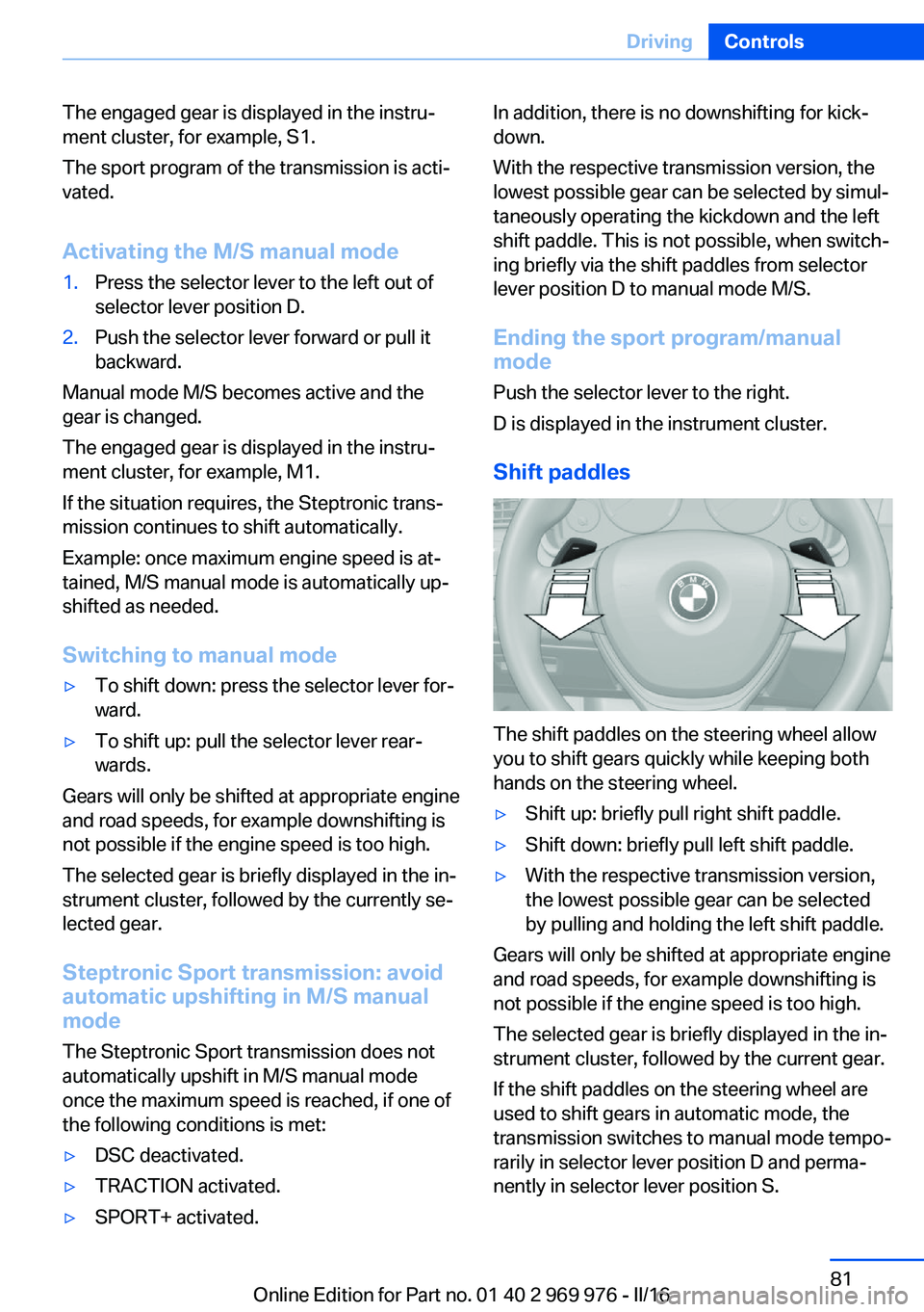
Shift paddles
The shift paddles on the steering wheel allow
you to shift gears quickly while keeping both
hands on the steering wheel.
▷Shift up: briefly pull right shift paddle.▷Shift down: briefly pull left shift paddle.▷With the respective transmission version,
the lowest possible gear can be selected
by pulling and holding the left shift paddle.
Gears will only be shifted at appropriate engine
and road speeds, for example downshifting is
not possible if the engine speed is too high.
The selected gear is briefly displayed in the in‐
strument cluster, followed by the current gear.
If the shift paddles on the steering wheel are
used to shift gears in automatic mode, the
transmission switches to manual mode tempo‐
rarily in selector lever position D and perma‐
nently in selector lever position S.
Seite 81DrivingControls81
Online Edition for Part no. 01 40 2 969 976 - II/16
Page 82 of 265
In selector lever position D, after conservative
driving for a certain amount of time in manual
mode or if there has been no acceleration or
shifting of the shift paddles within a certain
amount of time, the transmission switches
back to automatic mode.
Displays in the instrument cluster The selector lever position is dis‐played, for example: P.
Electronic unlocking of the
transmission lock
General information
Electronically unlock the transmission lock to
maneuver vehicle from the danger area.
Unlocking is possible, if the starter can spin the
engine.
Before unlocking the transmission lock, apply
the parking brake to prevent the vehicle from
rolling away.
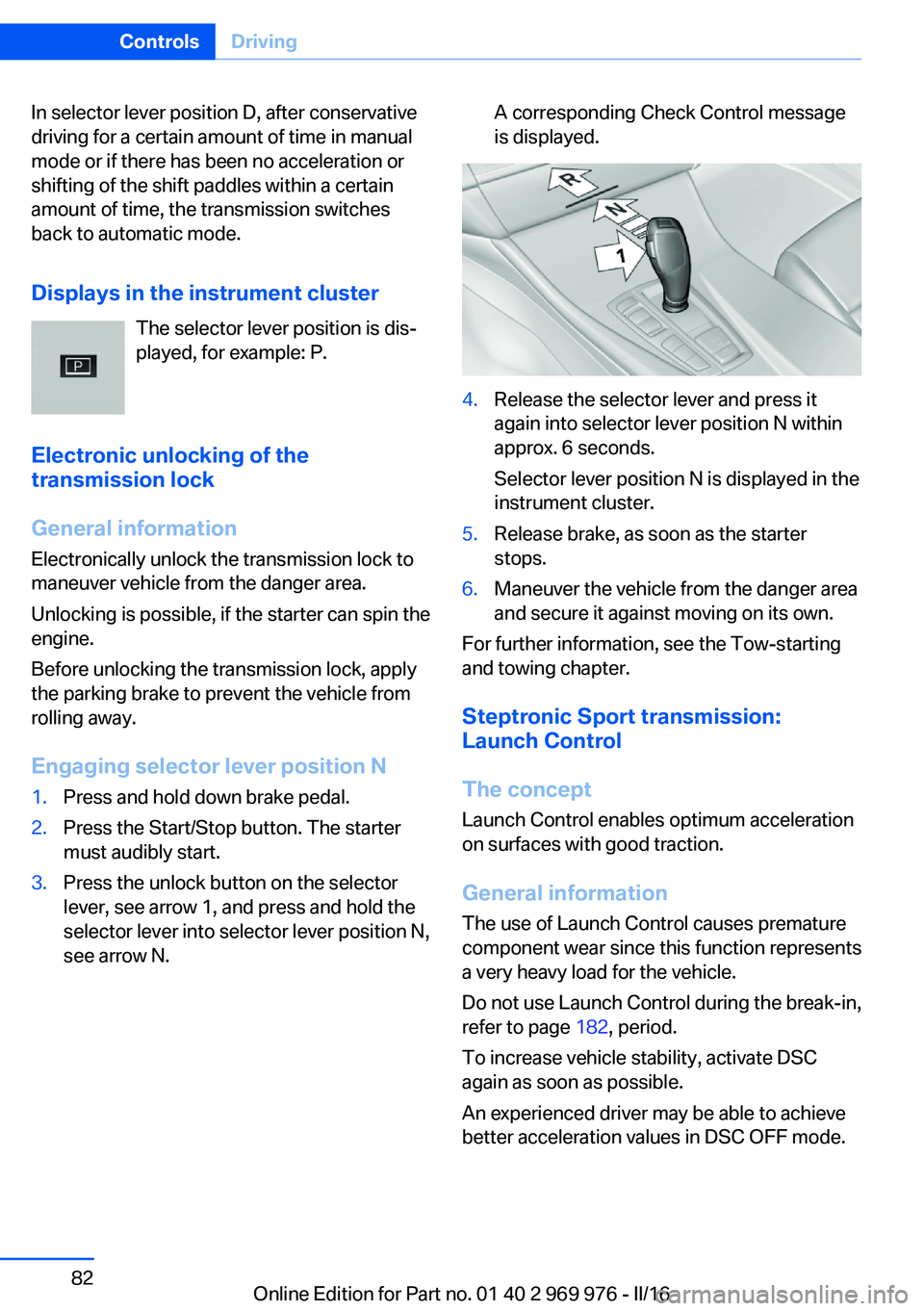
Engaging selector lever position N1.Press and hold down brake pedal.2.Press the Start/Stop button. The starter
must audibly start.3.Press the unlock button on the selector
lever, see arrow 1, and press and hold the
selector lever into selector lever position N,
see arrow N.A corresponding Check Control message
is displayed.4.Release the selector lever and press it
again into selector lever position N within
approx. 6 seconds.
Selector lever position N is displayed in the
instrument cluster.5.Release brake, as soon as the starter
stops.6.Maneuver the vehicle from the danger area
and secure it against moving on its own.
For further information, see the Tow-starting
and towing chapter.
Steptronic Sport transmission:
Launch Control
The concept Launch Control enables optimum acceleration
on surfaces with good traction.
General information
The use of Launch Control causes premature
component wear since this function represents
a very heavy load for the vehicle.
Do not use Launch Control during the break-in,
refer to page 182, period.
To increase vehicle stability, activate DSC
again as soon as possible.
An experienced driver may be able to achieve
better acceleration values in DSC OFF mode.
Seite 82ControlsDriving82
Online Edition for Part no. 01 40 2 969 976 - II/16
Page 89 of 265
Fuel gaugeVehicle tilt position may cause
the display to vary.
Depending on the equipment
version, the arrow beside the
fuel pump symbol shows which
side of the vehicle the fuel filler flap is on.
Information on refueling, refer to page 198.
Tachometer Always avoid engine speeds in the red warning
field. In this range, the fuel supply is inter‐
rupted to protect the engine.
Engine oil temperature▷Cold engine: the pointer is at
the low temperature end.
Drive at moderate engine
and vehicle speeds.▷Normal operating tempera‐
ture: the pointer is in the
middle or in the left half of
the temperature display.▷Hot engine: the pointer is at the high end of
the temperature range. In addition, a Check
Control message is displayed.
Coolant temperature
If the coolant along with the engine becomes
too hot, a Check Control message is displayed.
Check the coolant level.
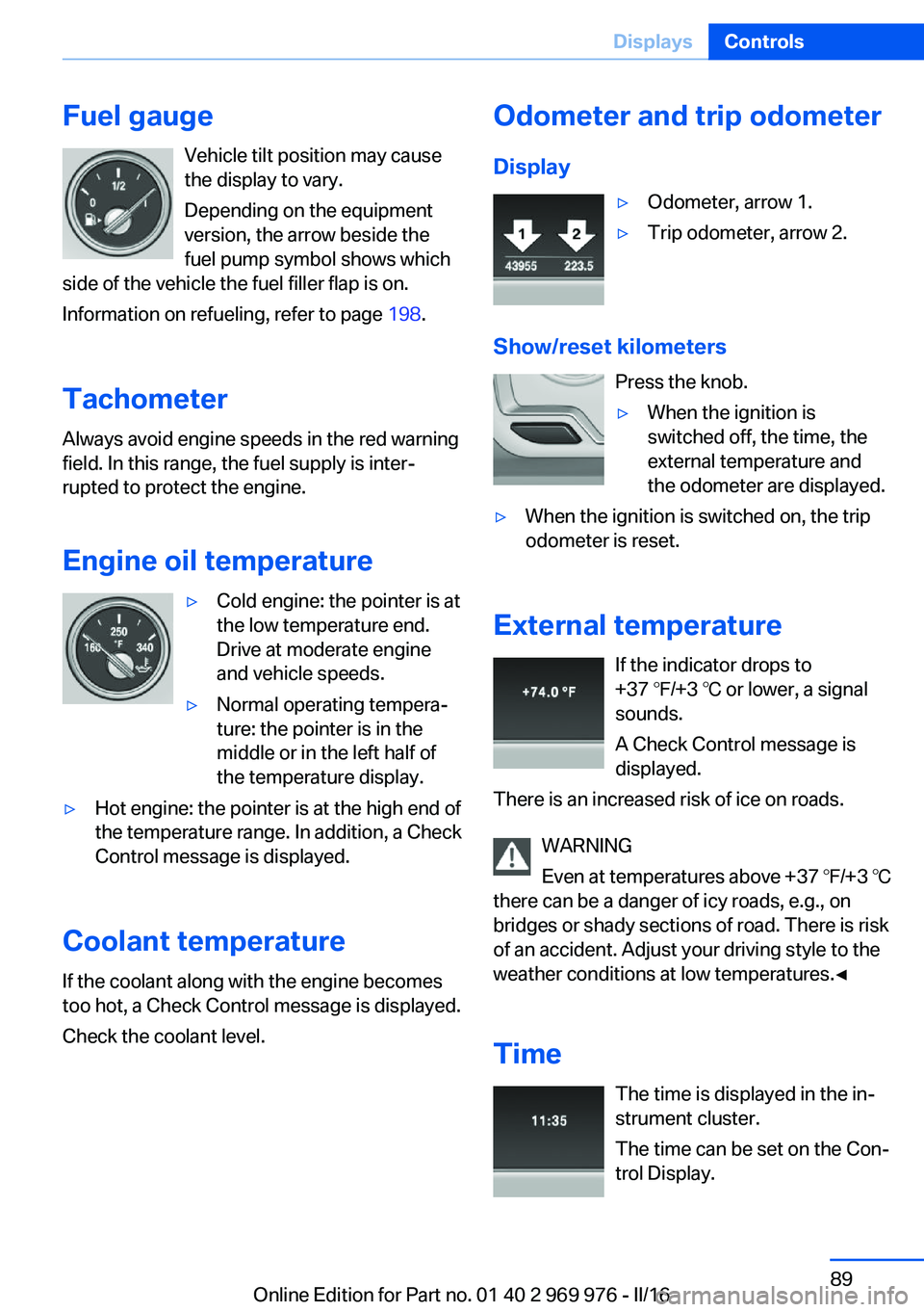
Odometer and trip odometer
Display▷Odometer, arrow 1.▷Trip odometer, arrow 2.
Show/reset kilometers Press the knob.
▷When the ignition is
switched off, the time, the
external temperature and
the odometer are displayed.▷When the ignition is switched on, the trip
odometer is reset.
External temperature
If the indicator drops to
+37 ℉/+3 ℃ or lower, a signal
sounds.
A Check Control message is displayed.
There is an increased risk of ice on roads.
WARNING
Even at temperatures above +37 ℉/+3 ℃
there can be a danger of icy roads, e.g., on
bridges or shady sections of road. There is risk
of an accident. Adjust your driving style to the
weather conditions at low temperatures.◀
Time The time is displayed in the in‐
strument cluster.
The time can be set on the Con‐
trol Display.
Seite 89DisplaysControls89
Online Edition for Part no. 01 40 2 969 976 - II/16
Page 91 of 265
Service requirements
The concept After the ignition is turned on the instrument
cluster briefly displays available driving dis‐
tance or time to the next scheduled mainte‐
nance.
A service advisor can read out the current
service requirements from your remote con‐
trol.
Display
Detailed information on service
requirements
More information on the scope of service re‐
quired can be displayed on the Control Dis‐
play.1."Vehicle info"2."Vehicle status"3. "Service required"
Required maintenance procedures and le‐
gally mandated inspections are displayed.4.Select an entry to call up detailed informa‐
tion.
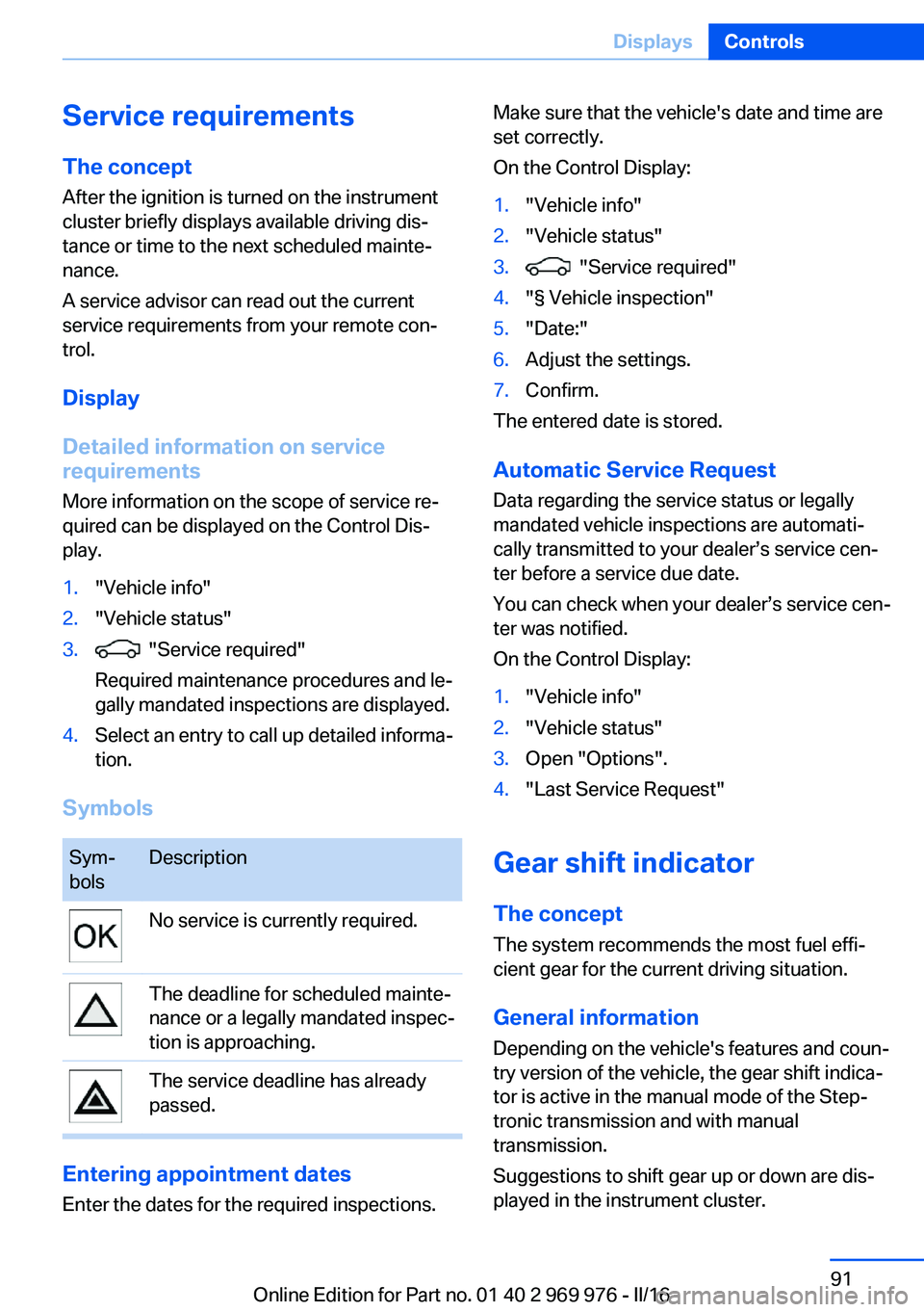
Symbols
Sym‐
bolsDescriptionNo service is currently required.The deadline for scheduled mainte‐
nance or a legally mandated inspec‐
tion is approaching.The service deadline has already
passed.
Entering appointment dates
Enter the dates for the required inspections.
Make sure that the vehicle's date and time are
set correctly.
On the Control Display:1."Vehicle info"2."Vehicle status"3. "Service required"4."§ Vehicle inspection"5."Date:"6.Adjust the settings.7.Confirm.
The entered date is stored.
Automatic Service Request
Data regarding the service status or legally
mandated vehicle inspections are automati‐
cally transmitted to your dealer’s service cen‐
ter before a service due date.
You can check when your dealer’s service cen‐
ter was notified.
On the Control Display:
1."Vehicle info"2."Vehicle status"3.Open "Options".4."Last Service Request"
Gear shift indicator
The conceptThe system recommends the most fuel effi‐
cient gear for the current driving situation.
General information
Depending on the vehicle's features and coun‐
try version of the vehicle, the gear shift indica‐
tor is active in the manual mode of the Step‐
tronic transmission and with manual
transmission.
Suggestions to shift gear up or down are dis‐
played in the instrument cluster.
Seite 91DisplaysControls91
Online Edition for Part no. 01 40 2 969 976 - II/16
Page 111 of 265
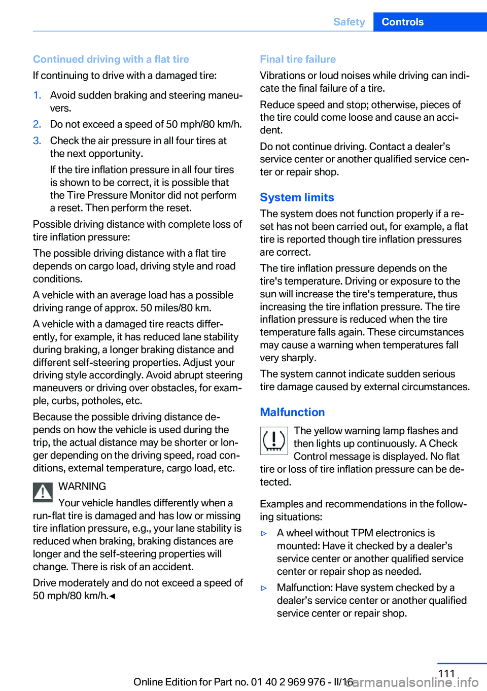
Continued driving with a flat tire
If continuing to drive with a damaged tire:1.Avoid sudden braking and steering maneu‐
vers.2.Do not exceed a speed of 50 mph/80 km/h.3.Check the air pressure in all four tires at
the next opportunity.
If the tire inflation pressure in all four tires
is shown to be correct, it is possible that
the Tire Pressure Monitor did not perform
a reset. Then perform the reset.
Possible driving distance with complete loss of
tire inflation pressure:
The possible driving distance with a flat tire
depends on cargo load, driving style and road
conditions.
A vehicle with an average load has a possible
driving range of approx. 50 miles/80 km.
A vehicle with a damaged tire reacts differ‐
ently, for example, it has reduced lane stability
during braking, a longer braking distance and
different self-steering properties. Adjust your
driving style accordingly. Avoid abrupt steering
maneuvers or driving over obstacles, for exam‐
ple, curbs, potholes, etc.
Because the possible driving distance de‐
pends on how the vehicle is used during the
trip, the actual distance may be shorter or lon‐
ger depending on the driving speed, road con‐
ditions, external temperature, cargo load, etc.
WARNING
Your vehicle handles differently when a
run-flat tire is damaged and has low or missing
tire inflation pressure, e.g., your lane stability is
reduced when braking, braking distances are
longer and the self-steering properties will
change. There is risk of an accident.
Drive moderately and do not exceed a speed of
50 mph/80 km/h.◀
Final tire failure
Vibrations or loud noises while driving can indi‐
cate the final failure of a tire.
Reduce speed and stop; otherwise, pieces of
the tire could come loose and cause an acci‐
dent.
Do not continue driving. Contact a dealer’s
service center or another qualified service cen‐
ter or repair shop.
System limits
The system does not function properly if a re‐
set has not been carried out, for example, a flat
tire is reported though tire inflation pressures
are correct.
The tire inflation pressure depends on the
tire's temperature. Driving or exposure to the
sun will increase the tire's temperature, thus
increasing the tire inflation pressure. The tire
inflation pressure is reduced when the tire
temperature falls again. These circumstances
may cause a warning when temperatures fall
very sharply.
The system cannot indicate sudden serious
tire damage caused by external circumstances.
Malfunction The yellow warning lamp flashes and
then lights up continuously. A Check
Control message is displayed. No flat
tire or loss of tire inflation pressure can be de‐
tected.
Examples and recommendations in the follow‐
ing situations:▷A wheel without TPM electronics is
mounted: Have it checked by a dealer’s
service center or another qualified service
center or repair shop as needed.▷Malfunction: Have system checked by a
dealer’s service center or another qualified
service center or repair shop.Seite 111SafetyControls111
Online Edition for Part no. 01 40 2 969 976 - II/16