relé BMW X3 3.0I 2007 E83 User Guide
[x] Cancel search | Manufacturer: BMW, Model Year: 2007, Model line: X3 3.0I, Model: BMW X3 3.0I 2007 E83Pages: 139, PDF Size: 4.74 MB
Page 54 of 139
Technology for comfort, convenience and safety
52
Activating HDC
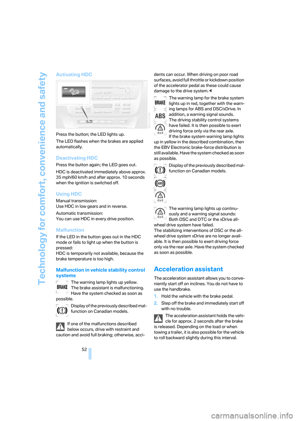
Press the button; the LED lights up.
The LED flashes when the brakes are applied
automatically.
Deactivating HDC
Press the button again; the LED goes out.
HDC is deactivated immediately above approx.
35 mph/60 km/h and after approx. 10 seconds
when the ignition is switched off.
Using HDC
Manual transmission:
Use HDC in low gears and in reverse.
Automatic transmission:
You can use HDC in every drive position.
Malfunction
If the LED in the button goes out in the HDC
mode or fails to light up when the button is
pressed:
HDC is temporarily not available, because the
brake temperature is too high.
Malfunction in vehicle stability control
systems
The warning lamp lights up yellow.
The brake assistant is malfunctioning.
Have the system checked as soon as
possible.
Display of the previously described mal-
function on Canadian models.
If one of the malfunctions described
below occurs, drive with restraint and
caution and avoid full braking; otherwise, acci-dents can occur. When driving on poor road
surfaces, avoid full throttle or kickdown position
of the accelerator pedal as these could cause
damage to the drive system.<
The warning lamp for the brake system
lights up in red, together with the warn-
ing lamps for ABS and DSC/xDrive. In
addition, a warning signal sounds.
The driving stability control systems
have failed. It is then possible to exert
driving force only via the rear axle.
If the brake system warning lamp lights
up in yellow in the described combination, then
the EBV Electronic brake-force distribution is
still available. Have the system checked as soon
as possible.
Display of the previously described mal-
function on Canadian models.
The warning lamp lights up continu-
ously and a warning signal sounds:
Both DSC and DTC or the xDrive all-
wheel drive system have failed.
The stabilizing interventions of DSC or the all-
wheel drive system xDrive are no longer avail-
able. It is then possible to exert driving force
only via the rear axle. Have the system checked
as soon as possible.
Acceleration assistant
The acceleration assistant allows you to conve-
niently start off on inclines. You do not have to
use the handbrake.
1.Hold the vehicle with the brake pedal.
2.Step off the brake and immediately start off
with no trouble.
The acceleration assistant holds the vehi-
cle for approx. 2 seconds after the brake
is released. Depending on the load or when
towing a trailer, it is also possible for the vehicle
to roll backward slightly during this interval.
Page 55 of 139
Reference
At a glance
Controls
Driving tips
Mobility
53
After releasing the brake, start driving immedi-
ately; otherwise, the acceleration assistant will
no longer hold the vehicle after approx. 2 sec-
onds and the vehicle will start to roll back-
ward.<
Malfunction
The warning lamp for the brake system
lights up in yellow. The acceleration
assistant has failed. The vehicle will not
be held after the brake is released. Have the
system checked as soon as possible.
Flat Tire Monitor FTM*
The concept
The Flat Tire Monitor keeps track of the infla-
tion pressures in the four mounted tires as you
drive. The system triggers an alert whenever
the inflation pressure in one tire drops signifi-
cantly in relation to the pressure in another tire.
When a loss of pressure occurs, the rolling
radius changes and with it, the rotational speed
of the wheels. This change is detected and sig-
naled as a flat tire.
Functional requirement
To ensure the reliable signaling of a flat tire, the
system must be initialized at the correct tire
inflation pressure.
The initialization must be carried out after
each correction of the tire inflation pres-
sure and after every tire or wheel change.<
System limits
The Flat Tire Monitor cannot predict sud-
den severe tire damage caused by out-
side factors and does not detect a natural, even
pressure drop in all four tires.<
In the following situations, the system could be
delayed or malfunction:
>When the system has not been initialized
>When driving on snow-covered or slippery
road surfaces>Sporty driving style: slip in the drive wheels,
high lateral acceleration.
>When driving with snow chains
*
When driving with a compact wheel, the Flat
Tire Monitor cannot operate.
Initializing system
The initialization is completed while driv-
ing and can be interrupted at any time.
The initialization automatically continues when
driving resumes.
Do not initialize the system when driving with
snow chains
* or with a compact wheel.<
1.Start the engine just before driving, but do
not begin to drive.
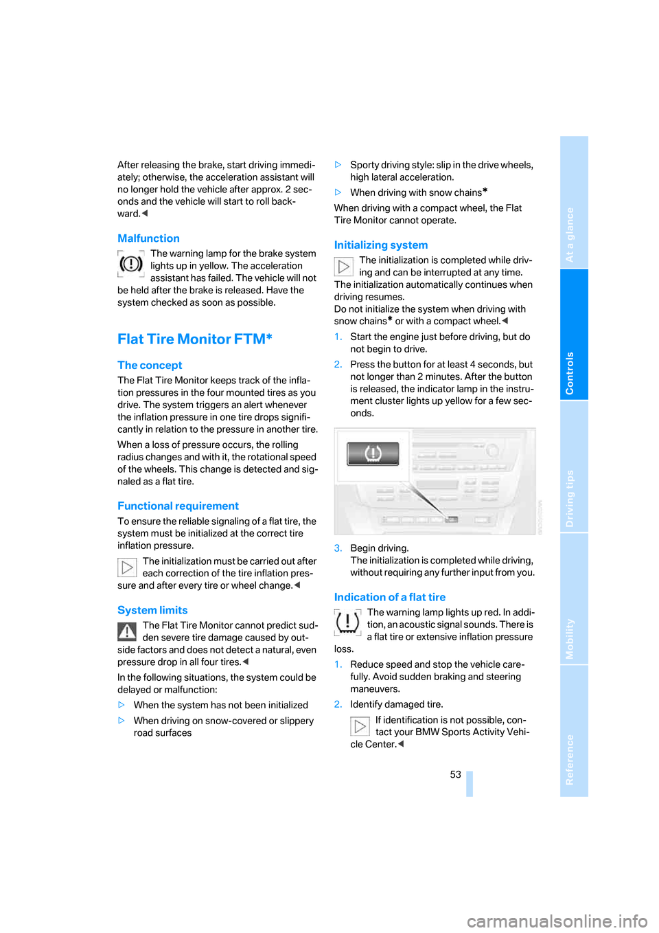
2.Press the button for at least 4 seconds, but
not longer than 2 minutes. After the button
is released, the indicator lamp in the instru-
ment cluster lights up yellow for a few sec-
onds.
3.Begin driving.
The initialization is completed while driving,
without requiring any further input from you.
Indication of a flat tire
The warning lamp lights up red. In addi-
tion, an acoustic signal sounds. There is
a flat tire or extensive inflation pressure
loss.
1.Reduce speed and stop the vehicle care-
fully. Avoid sudden braking and steering
maneuvers.
2.Identify damaged tire.
If identification is not possible, con-
tact your BMW Sports Activity Vehi-
cle Center.<
Page 58 of 139
Technology for comfort, convenience and safety
56
Airbags
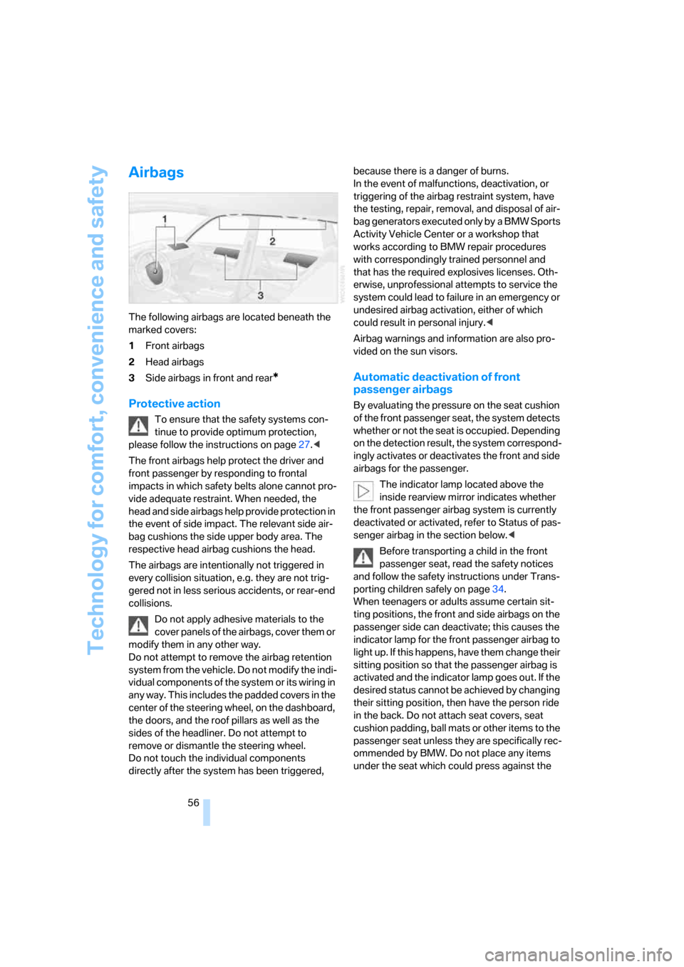
The following airbags are located beneath the
marked covers:
1Front airbags
2Head airbags
3Side airbags in front and rear
*
Protective action
To ensure that the safety systems con-
tinue to provide optimum protection,
please follow the instructions on page27.<
The front airbags help protect the driver and
front passenger by responding to frontal
impacts in which safety belts alone cannot pro-
vide adequate restraint. When needed, the
head and side airbags help provide protection in
the event of side impact. The relevant side air-
bag cushions the side upper body area. The
respective head airbag cushions the head.
The airbags are intentionally not triggered in
every collision situation, e.g. they are not trig-
gered not in less serious accidents, or rear-end
collisions.
Do not apply adhesive materials to the
cover panels of the airbags, cover them or
modify them in any other way.
Do not attempt to remove the airbag retention
system from the vehicle. Do not modify the indi-
vidual components of the system or its wiring in
any way. This includes the padded covers in the
center of the steering wheel, on the dashboard,
the doors, and the roof pillars as well as the
sides of the headliner. Do not attempt to
remove or dismantle the steering wheel.
Do not touch the individual components
directly after the system has been triggered, because there is a danger of burns.
In the event of malfunctions, deactivation, or
triggering of the airbag restraint system, have
the testing, repair, removal, and disposal of air-
bag generators executed only by a BMW Sports
Activity Vehicle Center or a workshop that
works according to BMW repair procedures
with correspondingly trained personnel and
that has the required explosives licenses. Oth-
erwise, unprofessional attempts to service the
system could lead to failure in an emergency or
undesired airbag activation, either of which
could result in personal injury.<
Airbag warnings and information are also pro-
vided on the sun visors.
Automatic deactivation of front
passenger airbags
By evaluating the pressure on the seat cushion
of the front passenger seat, the system detects
whether or not the seat is occupied. Depending
on the detection result, the system correspond-
ingly activates or deactivates the front and side
airbags for the passenger.
The indicator lamp located above the
inside rearview mirror indicates whether
the front passenger airbag system is currently
deactivated or activated, refer to Status of pas-
senger airbag in the section below.<
Before transporting a child in the front
passenger seat, read the safety notices
and follow the safety instructions under Trans-
porting children safely on page34.
When teenagers or adults assume certain sit-
ting positions, the front and side airbags on the
passenger side can deactivate; this causes the
indicator lamp for the front passenger airbag to
light up. If this happens, have them change their
sitting position so that the passenger airbag is
activated and the indicator lamp goes out. If the
desired status cannot be achieved by changing
their sitting position, then have the person ride
in the back. Do not attach seat covers, seat
cushion padding, ball mats or other items to the
passenger seat unless they are specifically rec-
ommended by BMW. Do not place any items
under the seat which could press against the
Page 69 of 139
Reference
At a glance
Controls
Driving tips
Mobility
67
Practical interior accessories
Integrated universal remote
control*
The concept
The integrated universal remote control can
replace as many as three hand-held transmit-
ters for various radio-controlled accessories,
such as garages, exterior gates, or lighting sys-
tems. The integrated universal remote control
recognizes and learns the transmitted signal of
each of the original hand-held transmitters.
The signal of an original hand-held transmitter
can be programmed on one of the three mem-
ory buttons1. Then, the programmed memory
button1 can operate the device whenever the
ignition is switched on. The LED2 indicates
transmission of the signal.
Should you sell your vehicle one day, be sure to
delete the stored programs beforehand for your
security, refer to page68.
To prevent possible damage or injury,
before programming or using the inte-
grated universal remote control, always inspect
the immediate area to make certain that no peo-
ple, animals or objects are within the travel
range of the device. Also, comply with the
safety precautions of the original hand-held
transmitter.<
Checking compatibility
If you see this symbol on the packaging
or in the manual supplied with the origi-
nal hand-held transmitter, then it is safe
to assume that the radio-controlled device is
compatible with the integrated universal
remote control.
If you have additional questions, please
ask at your BMW Sports Activity Vehicle
Center or call: 1-800-355-3515.
You can find also information on the Internet at:
www.bmwusa.com or
www.homelink.com. HomeLink is a registered trademark of
Johnson Controls, Inc.<
Programming
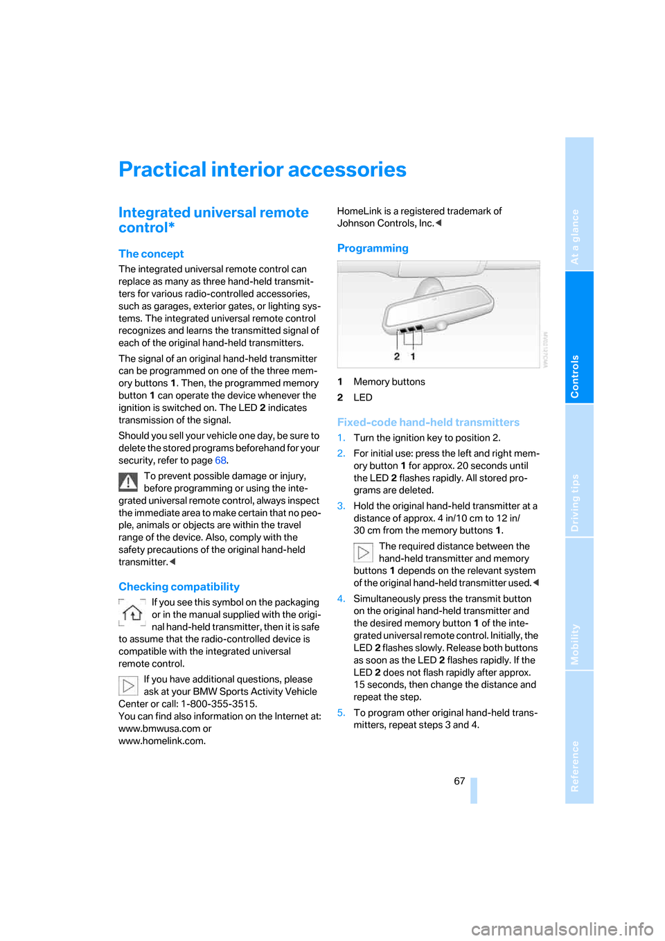
1Memory buttons
2LED
Fixed-code hand-held transmitters
1.Turn the ignition key to position 2.
2.For initial use: press the left and right mem-
ory button1 for approx. 20 seconds until
the LED2 flashes rapidly. All stored pro-
grams are deleted.
3.Hold the original hand-held transmitter at a
distance of approx. 4 in/10 cm to 12 in/
30 cm from the memory buttons1.
The required distance between the
hand-held transmitter and memory
buttons1 depends on the relevant system
of the original hand-held transmitter used.<
4.Simultaneously press the transmit button
on the original hand-held transmitter and
the desired memory button 1 of the inte-
grated universal remote control. Initially, the
LED2 flashes slowly. Release both buttons
as soon as the LED2 flashes rapidly. If the
LED2 does not flash rapidly after approx.
15 seconds, then change the distance and
repeat the step.
5.To program other original hand-held trans-
mitters, repeat steps 3 and 4.
Page 78 of 139
Practical interior accessories
76
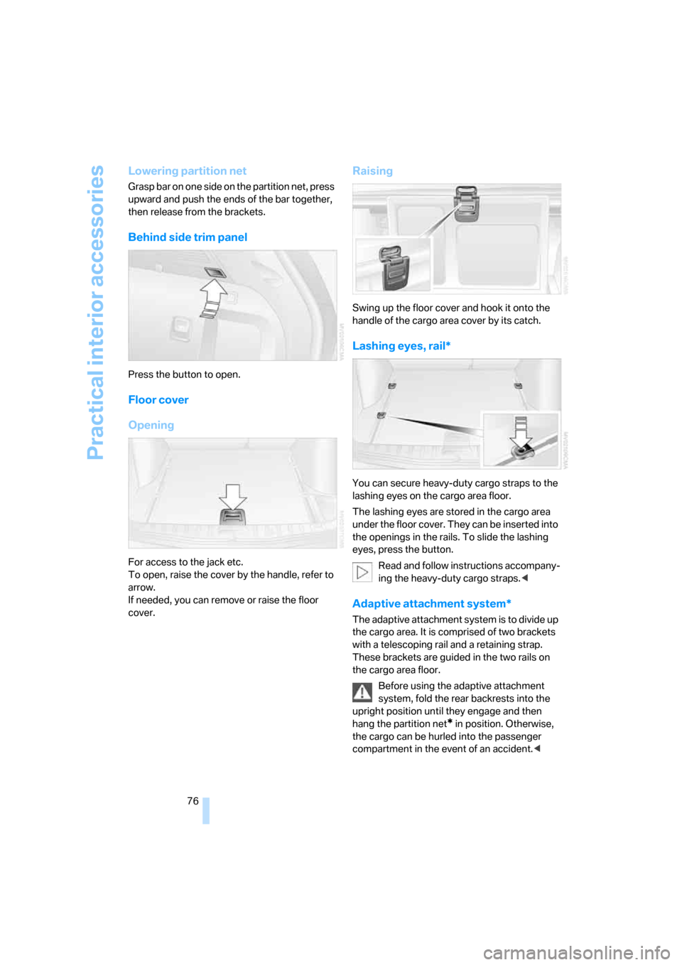
Lowering partition net
Grasp bar on one side on the partition net, press
upward and push the ends of the bar together,
then release from the brackets.
Behind side trim panel
Press the button to open.
Floor cover
Opening
For access to the jack etc.
To open, raise the cover by the handle, refer to
arrow.
If needed, you can remove or raise the floor
cover.
Raising
Swing up the floor cover and hook it onto the
handle of the cargo area cover by its catch.
Lashing eyes, rail*
You can secure heavy-duty cargo straps to the
lashing eyes on the cargo area floor.
The lashing eyes are stored in the cargo area
under the floor cover. They can be inserted into
the openings in the rails. To slide the lashing
eyes, press the button.
Read and follow instructions accompany-
ing the heavy-duty cargo straps.<
Adaptive attachment system*
The adaptive attachment system is to divide up
the cargo area. It is comprised of two brackets
with a telescoping rail and a retaining strap.
These brackets are guided in the two rails on
the cargo area floor.
Before using the adaptive attachment
system, fold the rear backrests into the
upright position until they engage and then
hang the partition net
* in position. Otherwise,
the cargo can be hurled into the passenger
compartment in the event of an accident.<
Page 90 of 139
Refueling
88
Refueling
Fuel cap
Opening
Always switch off the engine before
refueling. Otherwise, no fuel can be dis-
pensed into the tank and the Service Engine
Soon lamp lights up.<
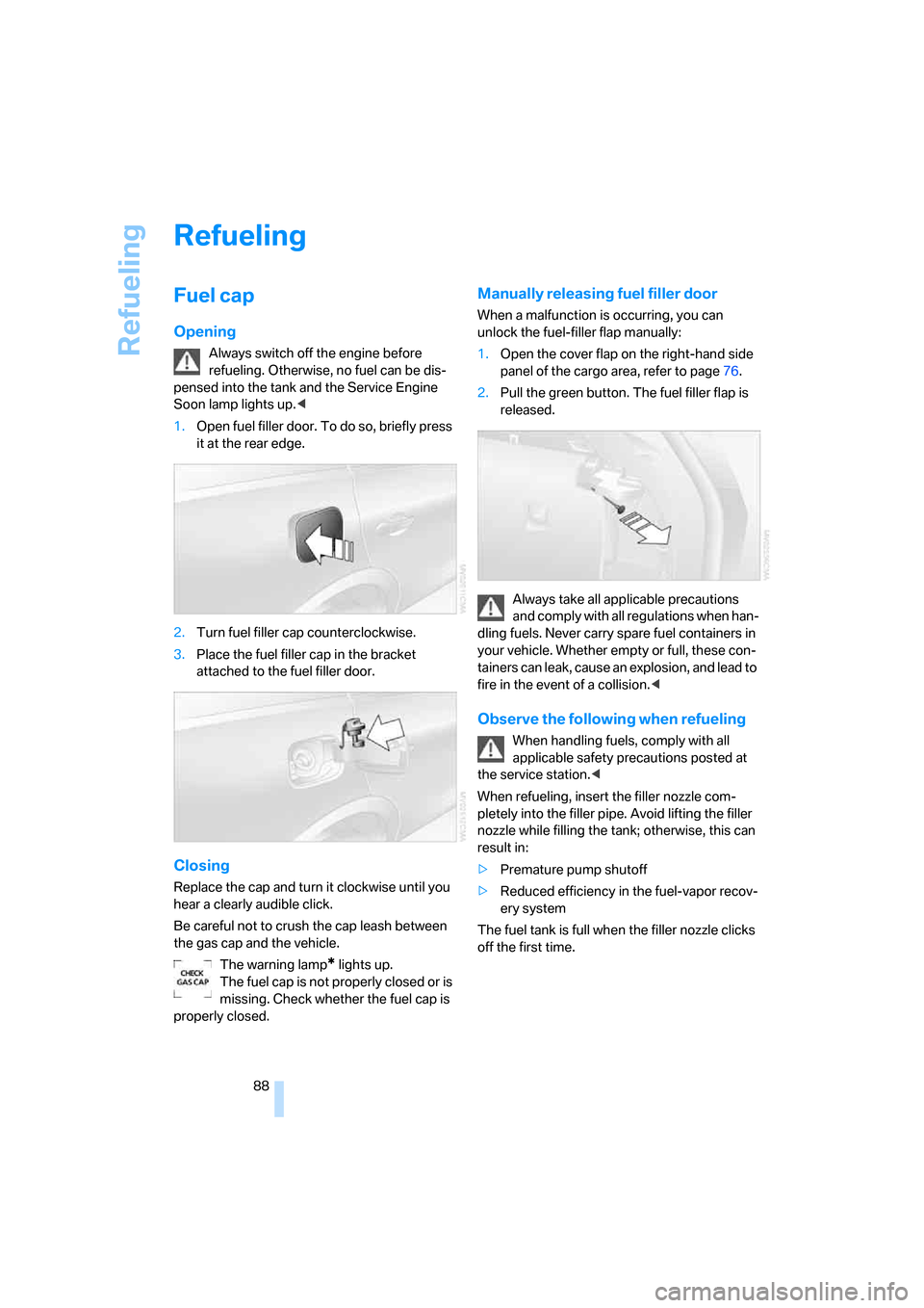
1.Open fuel filler door. To do so, briefly press
it at the rear edge.
2.Turn fuel filler cap counterclockwise.
3.Place the fuel filler cap in the bracket
attached to the fuel filler door.
Closing
Replace the cap and turn it clockwise until you
hear a clearly audible click.
Be careful not to crush the cap leash between
the gas cap and the vehicle.
The warning lamp
* lights up.
The fuel cap is not properly closed or is
missing. Check whether the fuel cap is
properly closed.
Manually releasing fuel filler door
When a malfunction is occurring, you can
unlock the fuel-filler flap manually:
1.Open the cover flap on the right-hand side
panel of the cargo area, refer to page76.
2.Pull the green button. The fuel filler flap is
released.
Always take all applicable precautions
and comply with all regulations when han-
dling fuels. Never carry spare fuel containers in
your vehicle. Whether empty or full, these con-
tainers can leak, cause an explosion, and lead to
fire in the event of a collision.<
Observe the following when refueling
When handling fuels, comply with all
applicable safety precautions posted at
the service station.<
When refueling, insert the filler nozzle com-
pletely into the filler pipe. Avoid lifting the filler
nozzle while filling the tank; otherwise, this can
result in:
>Premature pump shutoff
>Reduced efficiency in the fuel-vapor recov-
ery system
The fuel tank is full when the filler nozzle clicks
off the first time.
Page 99 of 139
Reference
At a glance
Controls
Driving tips
Mobility
97
Under the hood
Never attempt to perform any service or
repair operations on your vehicle without
the required professional technical training. If
you are not familiar with the regulations to be
observed, have work on your vehicle carried out
only by your BMW Sports Activity Vehicle Cen-
ter or at a workshop that works according to
BMW repair procedures with appropriately
trained personnel. If this work is not carried out
properly, there is a danger of subsequent dam-
age and related safety hazards.<
Hood
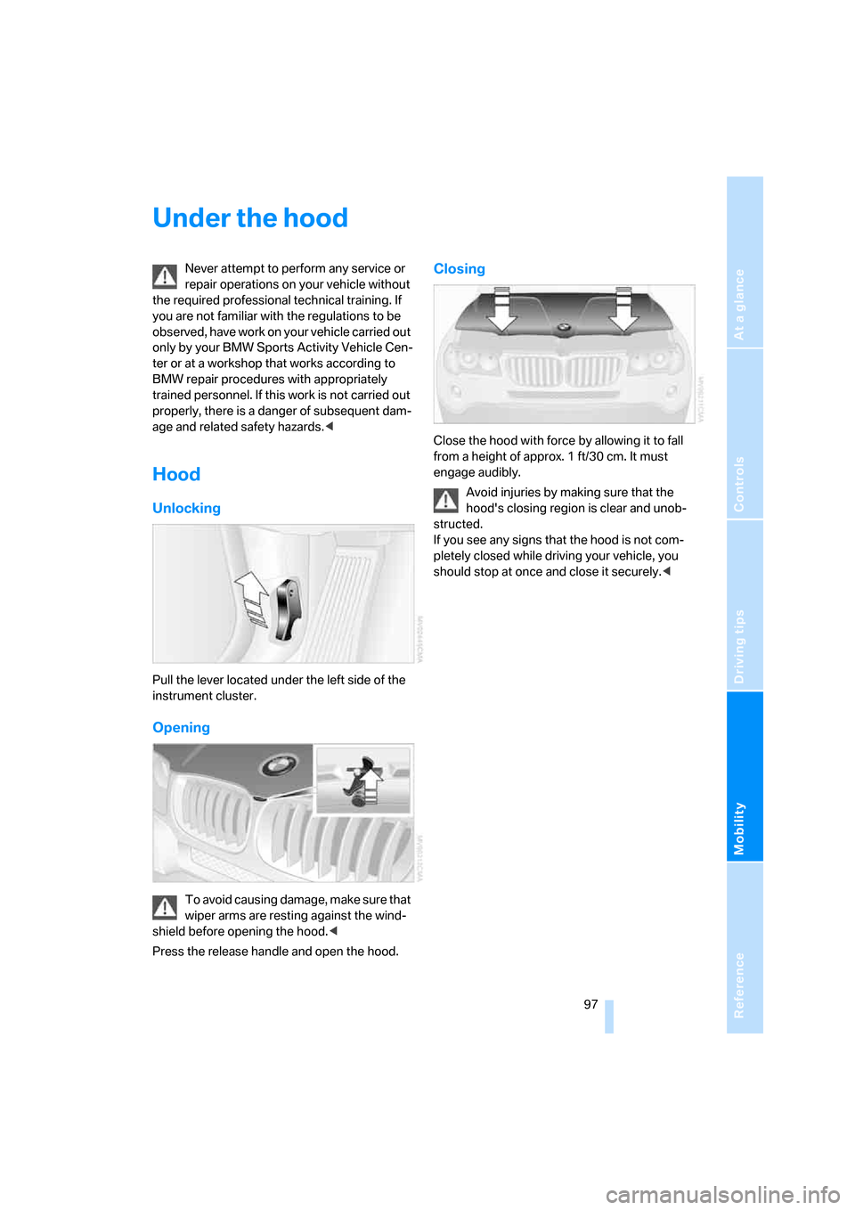
Unlocking
Pull the lever located under the left side of the
instrument cluster.
Opening
To avoid causing damage, make sure that
wiper arms are resting against the wind-
shield before opening the hood.<
Press the release handle and open the hood.
Closing
Close the hood with force by allowing it to fall
from a height of approx. 1 ft/30 cm. It must
engage audibly.
Avoid injuries by making sure that the
hood's closing region is clear and unob-
structed.
If you see any signs that the hood is not com-
pletely closed while driving your vehicle, you
should stop at once and close it securely.<
Page 103 of 139
Reference
At a glance
Controls
Driving tips
Mobility
101
Coolant
Warning lamp
The warning lamp lights up: coolant
level is too low; top off at the next
opportunity.
Do not open the cooling system when the
engine is hot. Escaping coolant can cause
burns.<
Coolant consists of water and coolant additive.
Not all commercially available additives are suit-
able for your BMW. Ask your BMW Sports
Activity Vehicle Center for suitable additives.
Only use suitable additives; otherwise,
engine damage may result. The additives
are harmful to your health, so follow the instruc-
tions on the containers.<
Always observe all applicable environ-
mental laws and regulations when dis-
posing of used coolant additives.<
Checking coolant level
1.Allow engine to cool.
2.Turn the cap of the expansion tank counter-
clockwise to allow any accumulated pres-
sure to escape, then continue turning to
open.
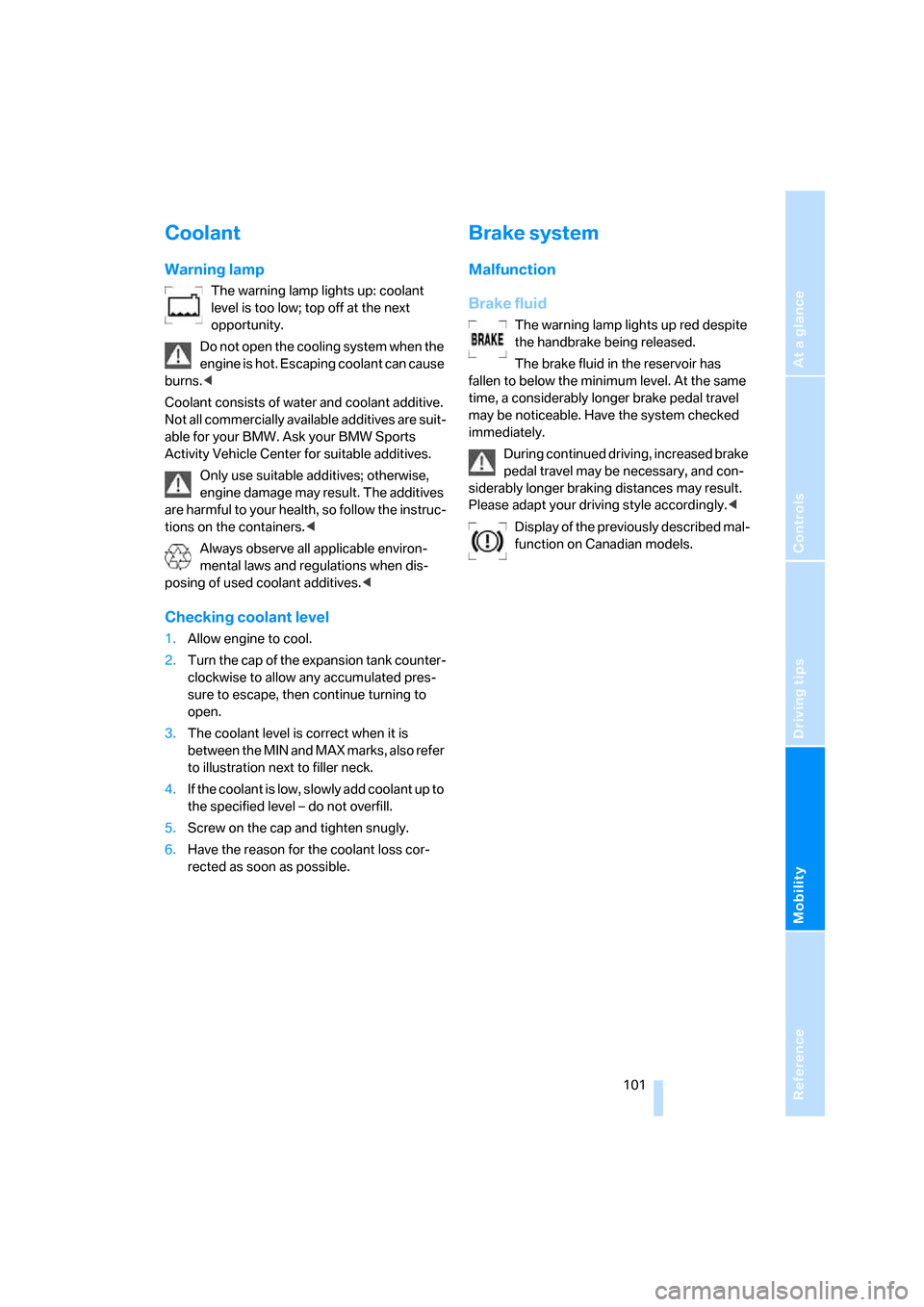
3.The coolant level is correct when it is
between the MIN and MAX marks, also refer
to illustration next to filler neck.
4.If the coolant is low, slowly add coolant up to
the specified level – do not overfill.
5.Screw on the cap and tighten snugly.
6.Have the reason for the coolant loss cor-
rected as soon as possible.
Brake system
Malfunction
Brake fluid
The warning lamp lights up red despite
the handbrake being released.
The brake fluid in the reservoir has
fallen to below the minimum level. At the same
time, a considerably longer brake pedal travel
may be noticeable. Have the system checked
immediately.
During continued driving, increased brake
pedal travel may be necessary, and con-
siderably longer braking distances may result.
Please adapt your driving style accordingly.<
Display of the previously described mal-
function on Canadian models.
Page 106 of 139
Replacing components
104
Replacing components
Onboard tool kit
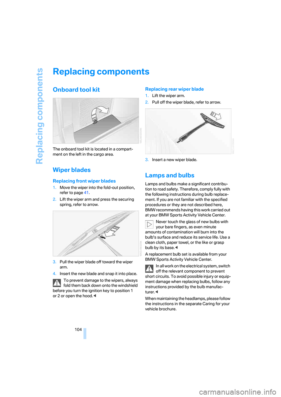
The onboard tool kit is located in a compart-
ment on the left in the cargo area.
Wiper blades
Replacing front wiper blades
1.Move the wiper into the fold-out position,
refer to page41.
2.Lift the wiper arm and press the securing
spring, refer to arrow.
3.Pull the wiper blade off toward the wiper
arm.
4.Insert the new blade and snap it into place.
To prevent damage to the wipers, always
fold them back down onto the windshield
before you turn the ignition key to position 1
or 2 or open the hood.<
Replacing rear wiper blade
1.Lift the wiper arm.
2.Pull off the wiper blade, refer to arrow.
3.Insert a new wiper blade.
Lamps and bulbs
Lamps and bulbs make a significant contribu-
tion to road safety. Therefore, comply fully with
the following instructions during bulb replace-
ment. If you are not familiar with the specified
procedures or they are not described here,
BMW recommends having this work carried out
at your BMW Sports Activity Vehicle Center.
Never touch the glass of new bulbs with
your bare fingers, as even minute
amounts of contamination will burn into the
bulb's surface and reduce its service life. Use a
clean cloth, paper towel, or the like or grasp
bulb by its base.<
A replacement bulb set is available from your
BMW Sports Activity Vehicle Center.
In all work on the electrical system, switch
off the relevant component to prevent
short circuits. To avoid possible injury or equip-
ment damage when replacing bulbs, follow any
instructions provided by the bulb manufac-
turer.<
When maintaining the headlamps, please follow
the instructions in the separate Caring for your
vehicle brochure.
Page 111 of 139
Reference
At a glance
Controls
Driving tips
Mobility
109
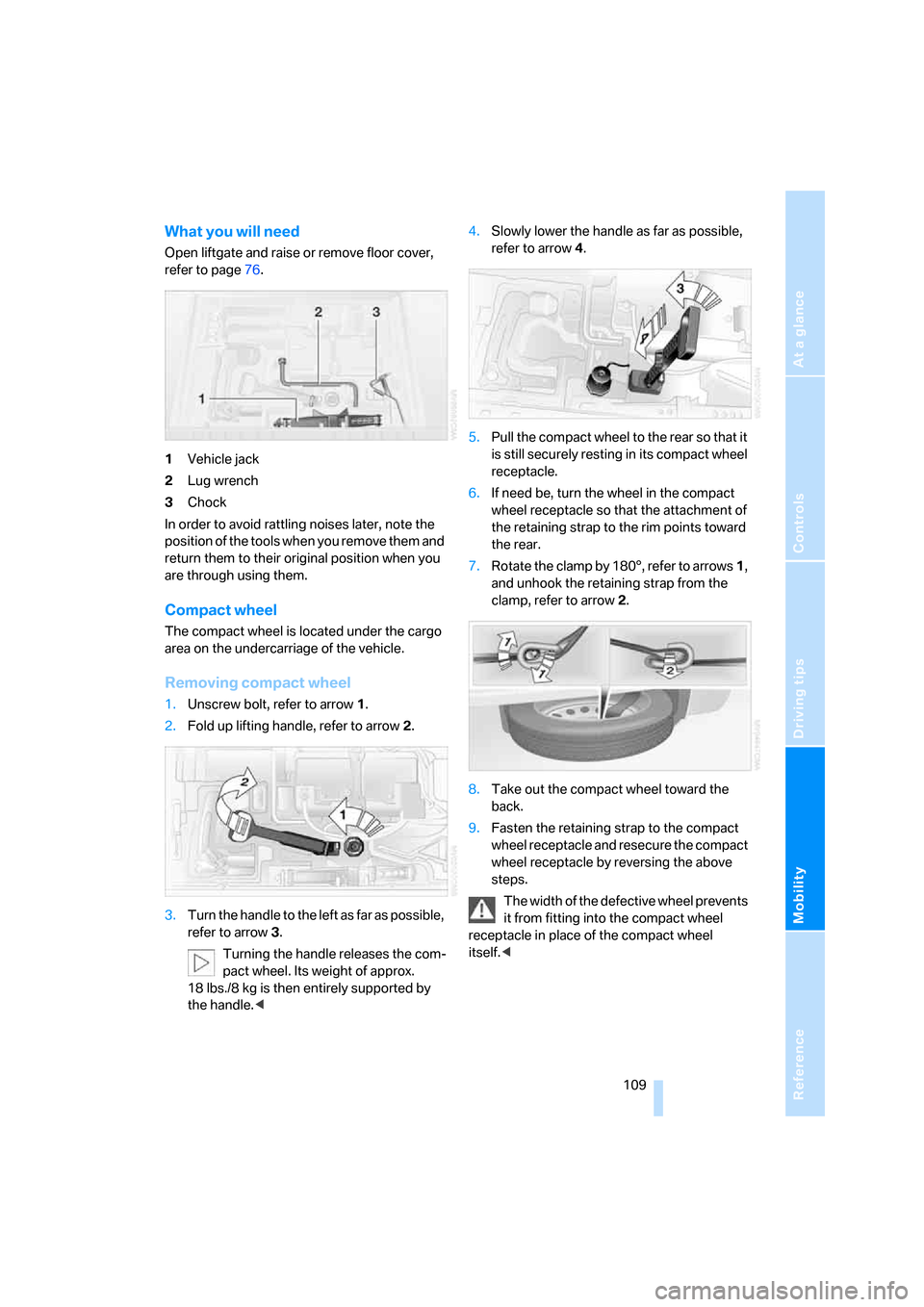
What you will need
Open liftgate and raise or remove floor cover,
refer to page76.
1Vehicle jack
2Lug wrench
3Chock
In order to avoid rattling noises later, note the
position of the tools when you remove them and
return them to their original position when you
are through using them.
Compact wheel
The compact wheel is located under the cargo
area on the undercarriage of the vehicle.
Removing compact wheel
1.Unscrew bolt, refer to arrow1.
2.Fold up lifting handle, refer to arrow2.
3.Turn the handle to the left as far as possible,
refer to arrow3.
Turning the handle releases the com-
pact wheel. Its weight of approx.
18 lbs./8 kg is then entirely supported by
the handle.<4.Slowly lower the handle as far as possible,
refer to arrow4.
5.Pull the compact wheel to the rear so that it
is still securely resting in its compact wheel
receptacle.
6.If need be, turn the wheel in the compact
wheel receptacle so that the attachment of
the retaining strap to the rim points toward
the rear.
7.Rotate the clamp by 180°, refer to arrows 1,
and unhook the retaining strap from the
clamp, refer to arrow 2.
8.Take out the compact wheel toward the
back.
9.Fasten the retaining strap to the compact
wheel receptacle and resecure the compact
wheel receptacle by reversing the above
steps.
The width of the defective wheel prevents
it from fitting into the compact wheel
receptacle in place of the compact wheel
itself.<