BMW X3 XDRIVE 28I 2013 Manual PDF
Manufacturer: BMW, Model Year: 2013, Model line: X3 XDRIVE 28I, Model: BMW X3 XDRIVE 28I 2013Pages: 211, PDF Size: 8.62 MB
Page 71 of 211
The vehicle only shifts up or down at appropriate
engine and road speeds, e.g., it does not shift
down if the engine speed is too high.
The selected gear is briefly displayed in the in‐
strument cluster, followed by the current gear.
Displays in the instrument cluster The transmission position is dis‐
played, e.g.: P.Seite 71DrivingControls71
Online Edition for Part no. 01 40 2 903 813 - 07 12 490
Page 72 of 211
DisplaysVehicle equipment
All standard, country-specific and optional
equipment that is offered in the model series is
described in this chapter. Therefore, equipmentis also described that is not available in a vehicle,
e. g., because of the selected optional equip‐
ment or country variant. This also applies for
safety-related functions and systems.
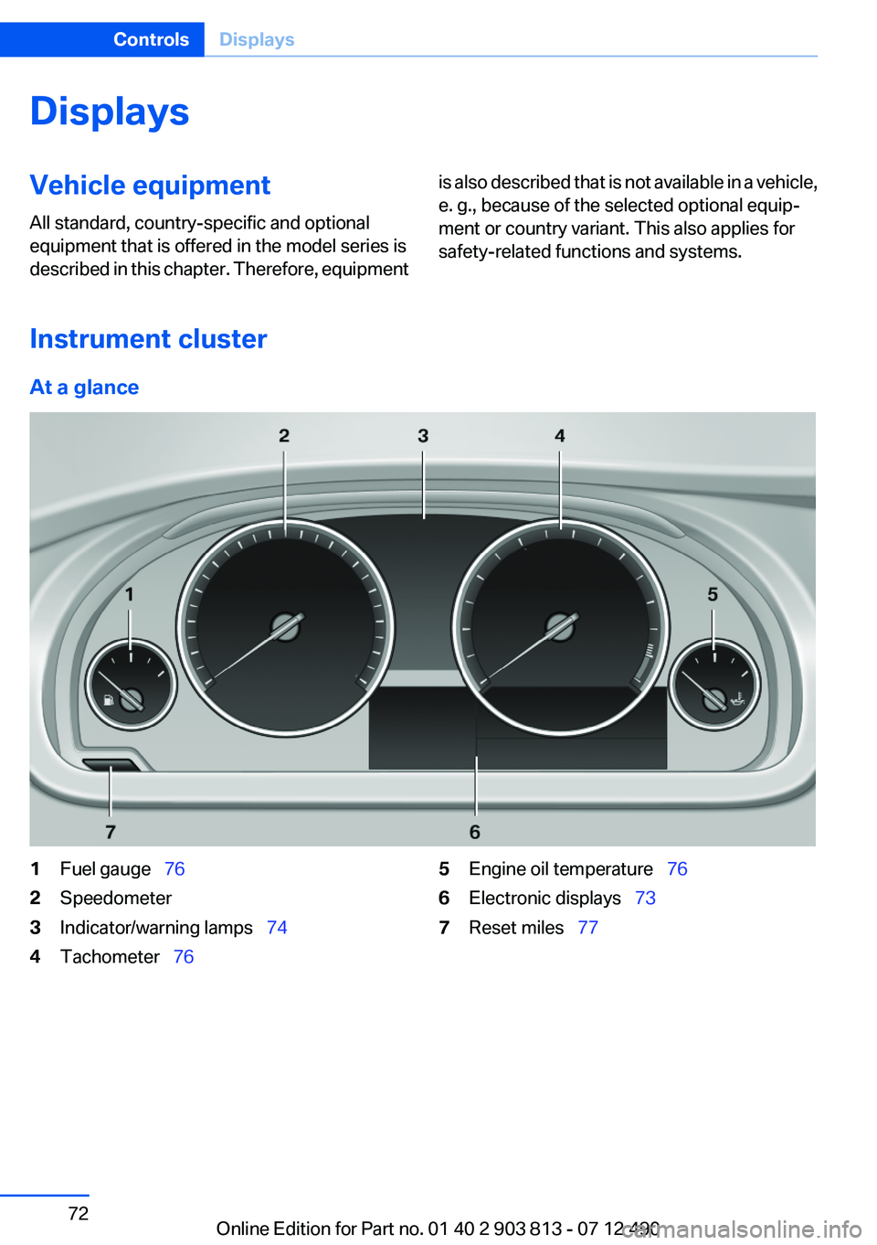
Instrument cluster
At a glance
1Fuel gauge 762Speedometer3Indicator/warning lamps 744Tachometer 765Engine oil temperature 766Electronic displays 737Reset miles 77Seite 72ControlsDisplays72
Online Edition for Part no. 01 40 2 903 813 - 07 12 490
Page 73 of 211
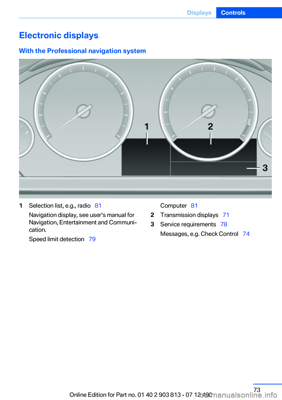
Electronic displays
With the Professional navigation system1Selection list, e.g., radio 81
Navigation display, see user's manual for
Navigation, Entertainment and Communi‐
cation.
Speed limit detection 79Computer 812Transmission displays 713Service requirements 78
Messages, e.g. Check Control 74Seite 73DisplaysControls73
Online Edition for Part no. 01 40 2 903 813 - 07 12 490
Page 74 of 211
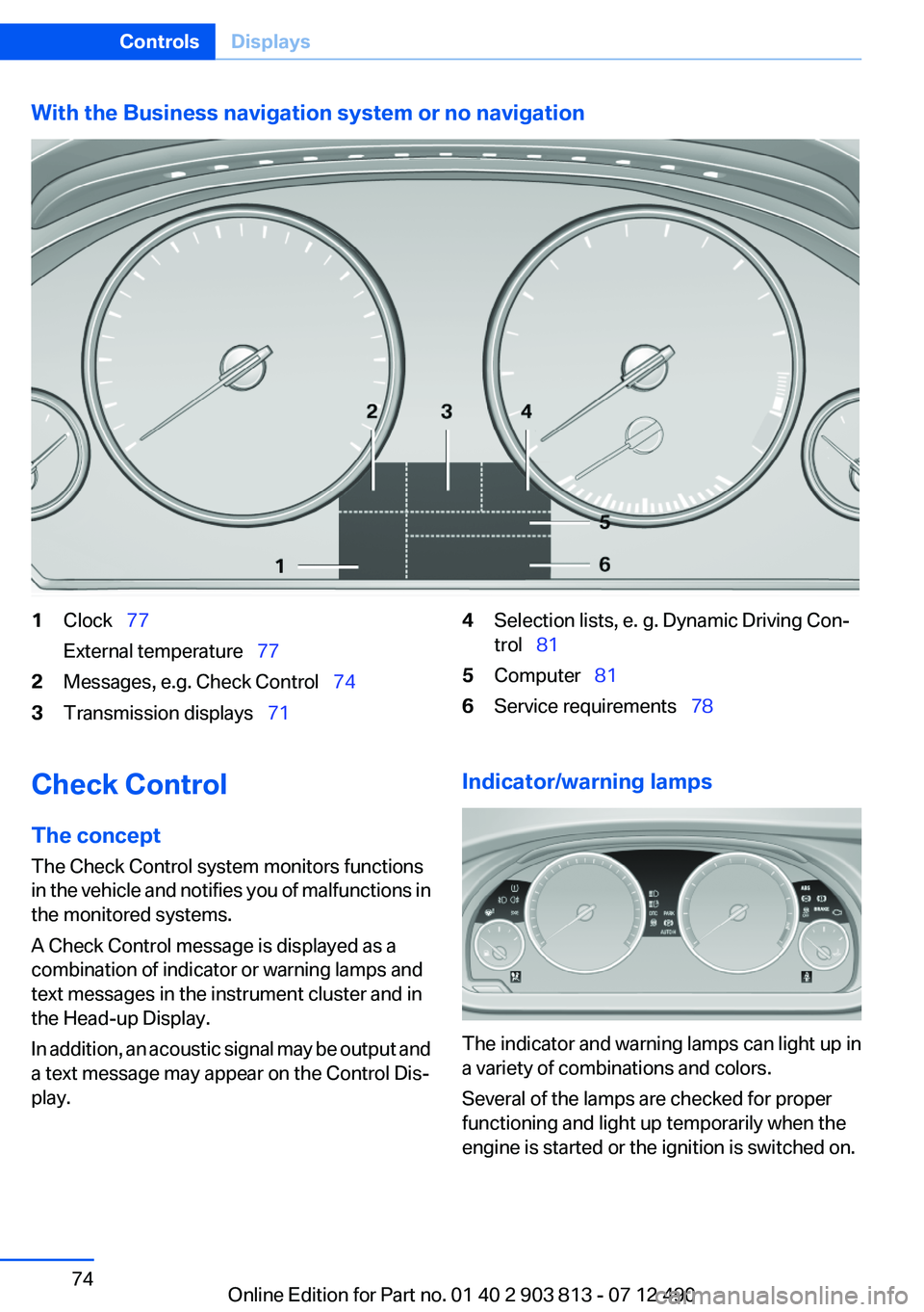
With the Business navigation system or no navigation1Clock 77
External temperature 772Messages, e.g. Check Control 743Transmission displays 714Selection lists, e. g. Dynamic Driving Con‐
trol 815Computer 816Service requirements 78Check Control
The concept
The Check Control system monitors functions
in the vehicle and notifies you of malfunctions in
the monitored systems.
A Check Control message is displayed as a
combination of indicator or warning lamps and
text messages in the instrument cluster and in
the Head-up Display.
In addition, an acoustic signal may be output and
a text message may appear on the Control Dis‐
play.Indicator/warning lamps
The indicator and warning lamps can light up in
a variety of combinations and colors.
Several of the lamps are checked for proper
functioning and light up temporarily when the
engine is started or the ignition is switched on.
Seite 74ControlsDisplays74
Online Edition for Part no. 01 40 2 903 813 - 07 12 490
Page 75 of 211
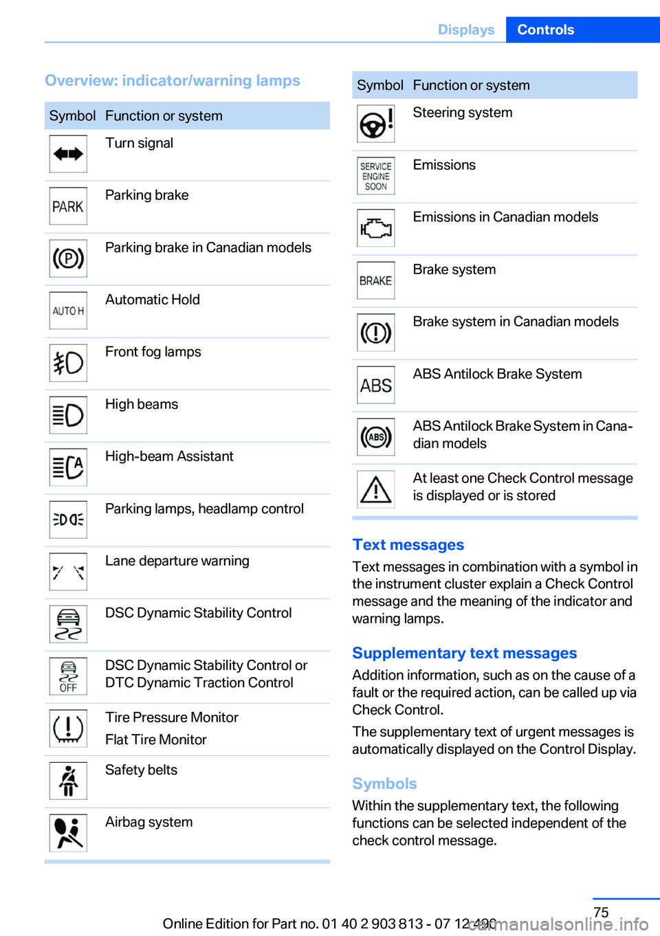
Overview: indicator/warning lampsSymbolFunction or systemTurn signalParking brakeParking brake in Canadian modelsAutomatic HoldFront fog lampsHigh beamsHigh-beam AssistantParking lamps, headlamp controlLane departure warningDSC Dynamic Stability ControlDSC Dynamic Stability Control or
DTC Dynamic Traction ControlTire Pressure Monitor
Flat Tire MonitorSafety beltsAirbag systemSymbolFunction or systemSteering systemEmissionsEmissions in Canadian modelsBrake systemBrake system in Canadian modelsABS Antilock Brake SystemABS Antilock Brake System in Cana‐
dian modelsAt least one Check Control message
is displayed or is stored
Text messages
Text messages in combination with a symbol in
the instrument cluster explain a Check Control
message and the meaning of the indicator and
warning lamps.
Supplementary text messages
Addition information, such as on the cause of a
fault or the required action, can be called up via
Check Control.
The supplementary text of urgent messages is
automatically displayed on the Control Display.
Symbols
Within the supplementary text, the following
functions can be selected independent of the
check control message.
Seite 75DisplaysControls75
Online Edition for Part no. 01 40 2 903 813 - 07 12 490
Page 76 of 211
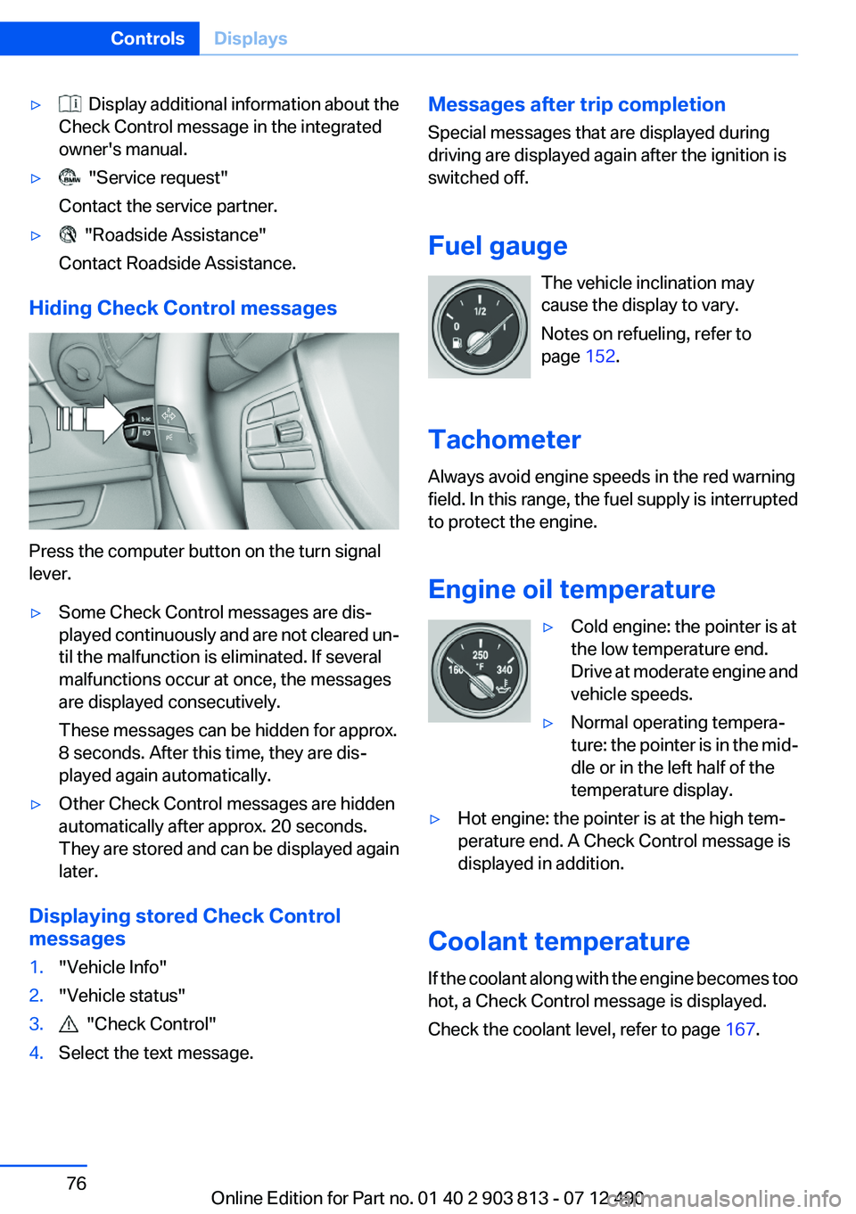
▷ Display additional information about the
Check Control message in the integrated
owner's manual.▷ "Service request"
Contact the service partner.▷ "Roadside Assistance"
Contact Roadside Assistance.
Hiding Check Control messages
Press the computer button on the turn signal
lever.
▷Some Check Control messages are dis‐
played continuously and are not cleared un‐
til the malfunction is eliminated. If several
malfunctions occur at once, the messages
are displayed consecutively.
These messages can be hidden for approx.
8 seconds. After this time, they are dis‐
played again automatically.▷Other Check Control messages are hidden
automatically after approx. 20 seconds.
They are stored and can be displayed again
later.
Displaying stored Check Control
messages
1."Vehicle Info"2."Vehicle status"3. "Check Control"4.Select the text message.Messages after trip completion
Special messages that are displayed during
driving are displayed again after the ignition is
switched off.
Fuel gauge The vehicle inclination may
cause the display to vary.
Notes on refueling, refer to
page 152.
Tachometer
Always avoid engine speeds in the red warning
field. In this range, the fuel supply is interrupted
to protect the engine.
Engine oil temperature▷Cold engine: the pointer is at
the low temperature end.
Drive at moderate engine and
vehicle speeds.▷Normal operating tempera‐
ture: the pointer is in the mid‐
dle or in the left half of the
temperature display.▷Hot engine: the pointer is at the high tem‐
perature end. A Check Control message is
displayed in addition.
Coolant temperature
If the coolant along with the engine becomes too
hot, a Check Control message is displayed.
Check the coolant level, refer to page 167.
Seite 76ControlsDisplays76
Online Edition for Part no. 01 40 2 903 813 - 07 12 490
Page 77 of 211
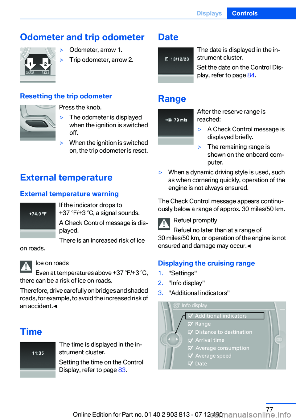
Odometer and trip odometer▷Odometer, arrow 1.▷Trip odometer, arrow 2.
Resetting the trip odometerPress the knob.
▷The odometer is displayed
when the ignition is switched
off.▷When the ignition is switched
on, the trip odometer is reset.
External temperature
External temperature warning If the indicator drops to
+37 ℉/+3 ℃, a signal sounds.
A Check Control message is dis‐
played.
There is an increased risk of ice
on roads.
Ice on roads
Even at temperatures above +37 ℉/+3 ℃,
there can be a risk of ice on roads.
Therefore, drive carefully on bridges and shaded
roads, for example, to avoid the increased risk of
an accident.◀
Time The time is displayed in the in‐
strument cluster.
Setting the time on the Control
Display, refer to page 83.
Date
The date is displayed in the in‐
strument cluster.
Set the date on the Control Dis‐
play, refer to page 84.
Range After the reserve range is
reached:▷A Check Control message is
displayed briefly.▷The remaining range is
shown on the onboard com‐
puter.▷When a dynamic driving style is used, such
as when cornering quickly, operation of the
engine is not always ensured.
The Check Control message appears continu‐
ously below a range of approx. 30 miles/50 km.
Refuel promptly
Refuel no later than at a range of
30 miles/50 km, or operation of the engine is not
ensured and damage may occur.◀
Displaying the cruising range
1."Settings"2."Info display"3."Additional indicators"Seite 77DisplaysControls77
Online Edition for Part no. 01 40 2 903 813 - 07 12 490
Page 78 of 211
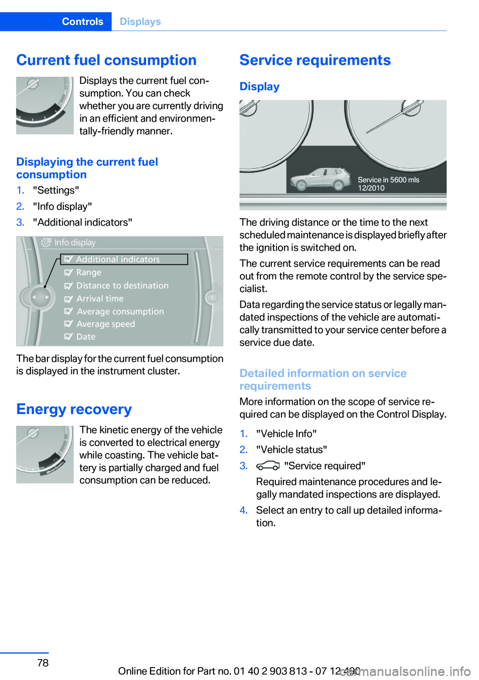
Current fuel consumptionDisplays the current fuel con‐
sumption. You can check
whether you are currently driving
in an efficient and environmen‐
tally-friendly manner.
Displaying the current fuel
consumption1."Settings"2."Info display"3."Additional indicators"
The bar display for the current fuel consumption
is displayed in the instrument cluster.
Energy recovery The kinetic energy of the vehicle
is converted to electrical energy
while coasting. The vehicle bat‐
tery is partially charged and fuel
consumption can be reduced.
Service requirements
Display
The driving distance or the time to the next
scheduled maintenance is displayed briefly after
the ignition is switched on.
The current service requirements can be read
out from the remote control by the service spe‐
cialist.
Data regarding the service status or legally man‐
dated inspections of the vehicle are automati‐
cally transmitted to your service center before a
service due date.
Detailed information on service
requirements
More information on the scope of service re‐
quired can be displayed on the Control Display.
1."Vehicle Info"2."Vehicle status"3. "Service required"
Required maintenance procedures and le‐
gally mandated inspections are displayed.4.Select an entry to call up detailed informa‐
tion.Seite 78ControlsDisplays78
Online Edition for Part no. 01 40 2 903 813 - 07 12 490
Page 79 of 211
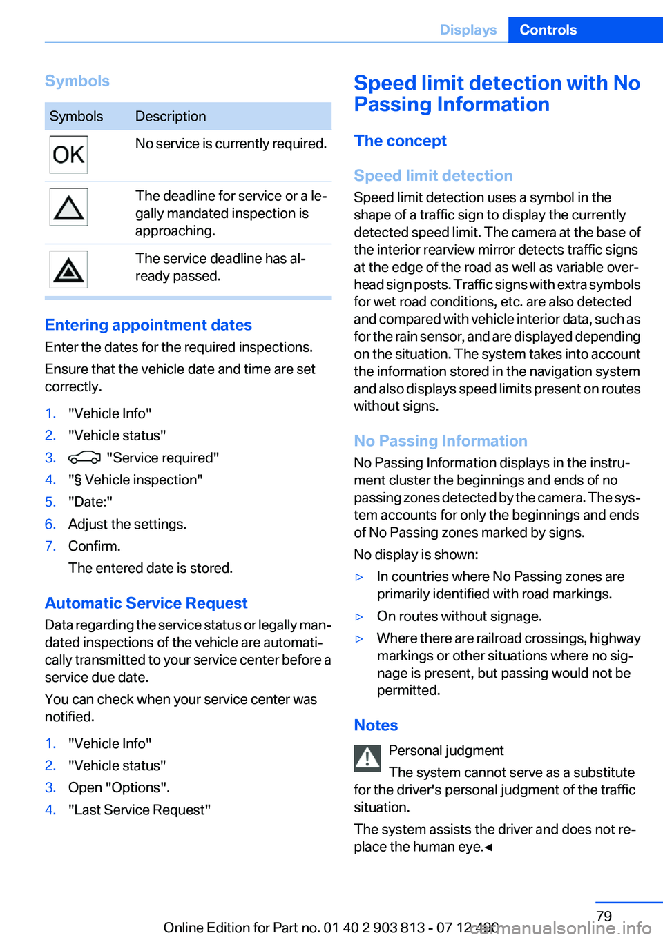
SymbolsSymbolsDescriptionNo service is currently required.The deadline for service or a le‐
gally mandated inspection is
approaching.The service deadline has al‐
ready passed.
Entering appointment dates
Enter the dates for the required inspections.
Ensure that the vehicle date and time are set
correctly.
1."Vehicle Info"2."Vehicle status"3. "Service required"4."§ Vehicle inspection"5."Date:"6.Adjust the settings.7.Confirm.
The entered date is stored.
Automatic Service Request
Data regarding the service status or legally man‐
dated inspections of the vehicle are automati‐
cally transmitted to your service center before a
service due date.
You can check when your service center was
notified.
1."Vehicle Info"2."Vehicle status"3.Open "Options".4."Last Service Request"Speed limit detection with No
Passing Information
The concept
Speed limit detection
Speed limit detection uses a symbol in the
shape of a traffic sign to display the currently
detected speed limit. The camera at the base of
the interior rearview mirror detects traffic signs
at the edge of the road as well as variable over‐
head sign posts. Traffic signs with extra symbols
for wet road conditions, etc. are also detected
and compared with vehicle interior data, such as
for the rain sensor, and are displayed depending
on the situation. The system takes into account
the information stored in the navigation system
and also displays speed limits present on routes
without signs.
No Passing Information
No Passing Information displays in the instru‐
ment cluster the beginnings and ends of no
passing zones detected by the camera. The sys‐
tem accounts for only the beginnings and ends
of No Passing zones marked by signs.
No display is shown:▷In countries where No Passing zones are
primarily identified with road markings.▷On routes without signage.▷Where there are railroad crossings, highway
markings or other situations where no sig‐
nage is present, but passing would not be
permitted.
Notes
Personal judgment
The system cannot serve as a substitute
for the driver's personal judgment of the traffic
situation.
The system assists the driver and does not re‐
place the human eye.◀
Seite 79DisplaysControls79
Online Edition for Part no. 01 40 2 903 813 - 07 12 490
Page 80 of 211
At a glance
Camera
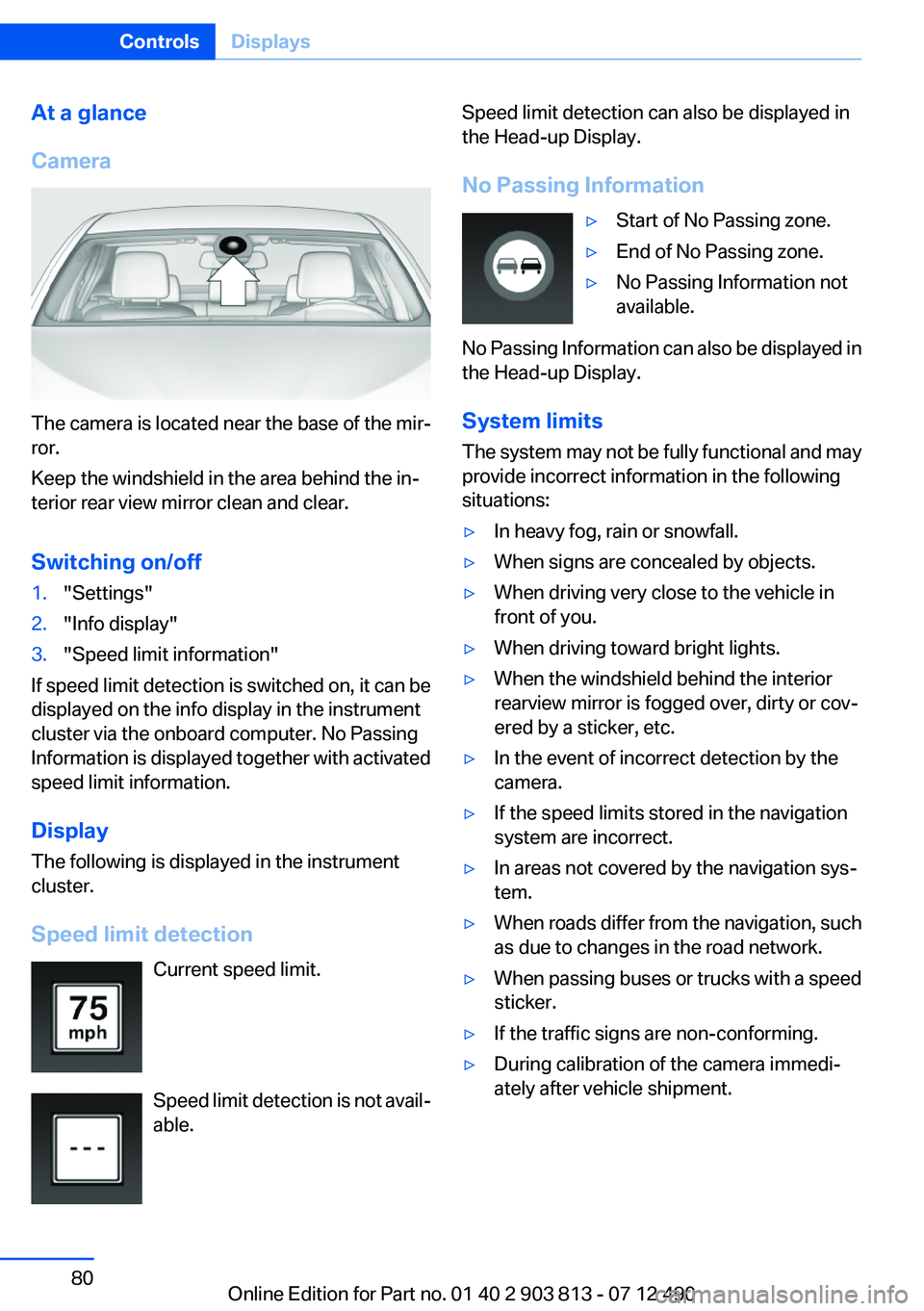
The camera is located near the base of the mir‐
ror.
Keep the windshield in the area behind the in‐
terior rear view mirror clean and clear.
Switching on/off
1."Settings"2."Info display"3."Speed limit information"
If speed limit detection is switched on, it can be
displayed on the info display in the instrument
cluster via the onboard computer. No Passing
Information is displayed together with activated
speed limit information.
Display
The following is displayed in the instrument
cluster.
Speed limit detection Current speed limit.
Speed limit detection is not avail‐
able.
Speed limit detection can also be displayed in
the Head-up Display.
No Passing Information▷Start of No Passing zone.▷End of No Passing zone.▷No Passing Information not
available.
No Passing Information can also be displayed in
the Head-up Display.
System limits
The system may not be fully functional and may
provide incorrect information in the following
situations:
▷In heavy fog, rain or snowfall.▷When signs are concealed by objects.▷When driving very close to the vehicle in
front of you.▷When driving toward bright lights.▷When the windshield behind the interior
rearview mirror is fogged over, dirty or cov‐
ered by a sticker, etc.▷In the event of incorrect detection by the
camera.▷If the speed limits stored in the navigation
system are incorrect.▷In areas not covered by the navigation sys‐
tem.▷When roads differ from the navigation, such
as due to changes in the road network.▷When passing buses or trucks with a speed
sticker.▷If the traffic signs are non-conforming.▷During calibration of the camera immedi‐
ately after vehicle shipment.Seite 80ControlsDisplays80
Online Edition for Part no. 01 40 2 903 813 - 07 12 490