lock BMW X5 1999 E53 Central Body Electronics Owner's Manual
[x] Cancel search | Manufacturer: BMW, Model Year: 1999, Model line: X5, Model: BMW X5 1999 E53Pages: 64, PDF Size: 4.03 MB
Page 45 of 64
ZKE - 45
AUTOMATIC CONTROL FUNCTION
The GM provides 12 volts (linear application providing soft on feature) to the interior light-
ing circuit when the one of the following input signal statuses change:
• Door contact hall sensor active (door opened)
• An Unlock request from the driver's door key lock hall sensors are received. This only
occurs if the ignition switch is off.
• An Unlock request is from the FZV keyless entry system is received via the K bus. This
only occurs if the ignition switch is off as well.
• The ignition switch is switched off and the vehicle exterior lights (LCM III) have been on
for a minimum of 2 minutes prior. This information is provided to the GM via the K bus.
• Active crash signal from the MRS III control module.
• Lock button of FZV key is pressed with the vehicle is already locked (interior search
function).
The GM gradually reduces the full 12 volt power supply (linear reduction providing soft off)
until the lights are off when the following input signal statuses change:
• Immediately after the ignition switch is turned to KL R with the driver's door hall sensor
door contact closed.
• When the vehicle is locked (single or double) with the door contacts closed.
• When the vehicle door contacts are closed. The lights remain on for 20 seconds and
then go to soft off.
• After the interior search function is activated, the lights will automatically turn off (soft off)
after 8 seconds.
• After 16 minutes with a door contact active (open door) and the key off, the lights are
switched off (consumer cutoff function).
• The component activation function of the DIS also has the ability to switch the lights.
The Interior lighting output circuit of the GM is approximately 3.5 amps with all lights on.
Page 46 of 64
ZKE - 46
ANTI-THEFT (DWA) SYSTEM
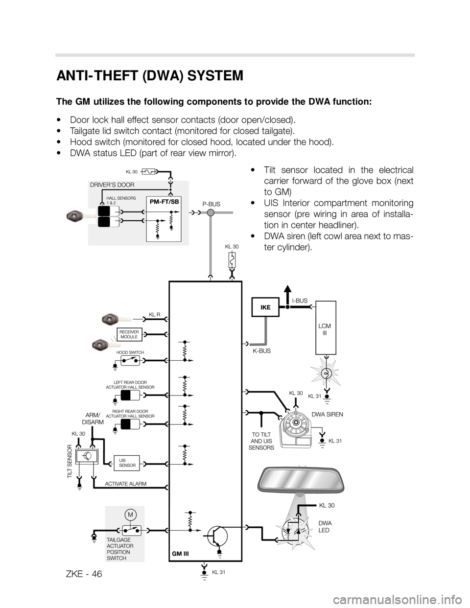
The GM utilizes the following components to provide the DWA function:
• Door lock hall effect sensor contacts (door open/closed).
• Tailgate lid switch contact (monitored for closed tailgate).
• Hood switch (monitored for closed hood, located under the hood).
• DWA status LED (part of rear view mirror).
• Tilt sensor located in the electrical
carrier forward of the glove box (next
to GM)
• UIS Interior compartment monitoring
sensor (pre wiring in area of installa-
tion in center headliner).
• DWA siren (left cowl area next to mas-
ter cylinder).
Page 47 of 64
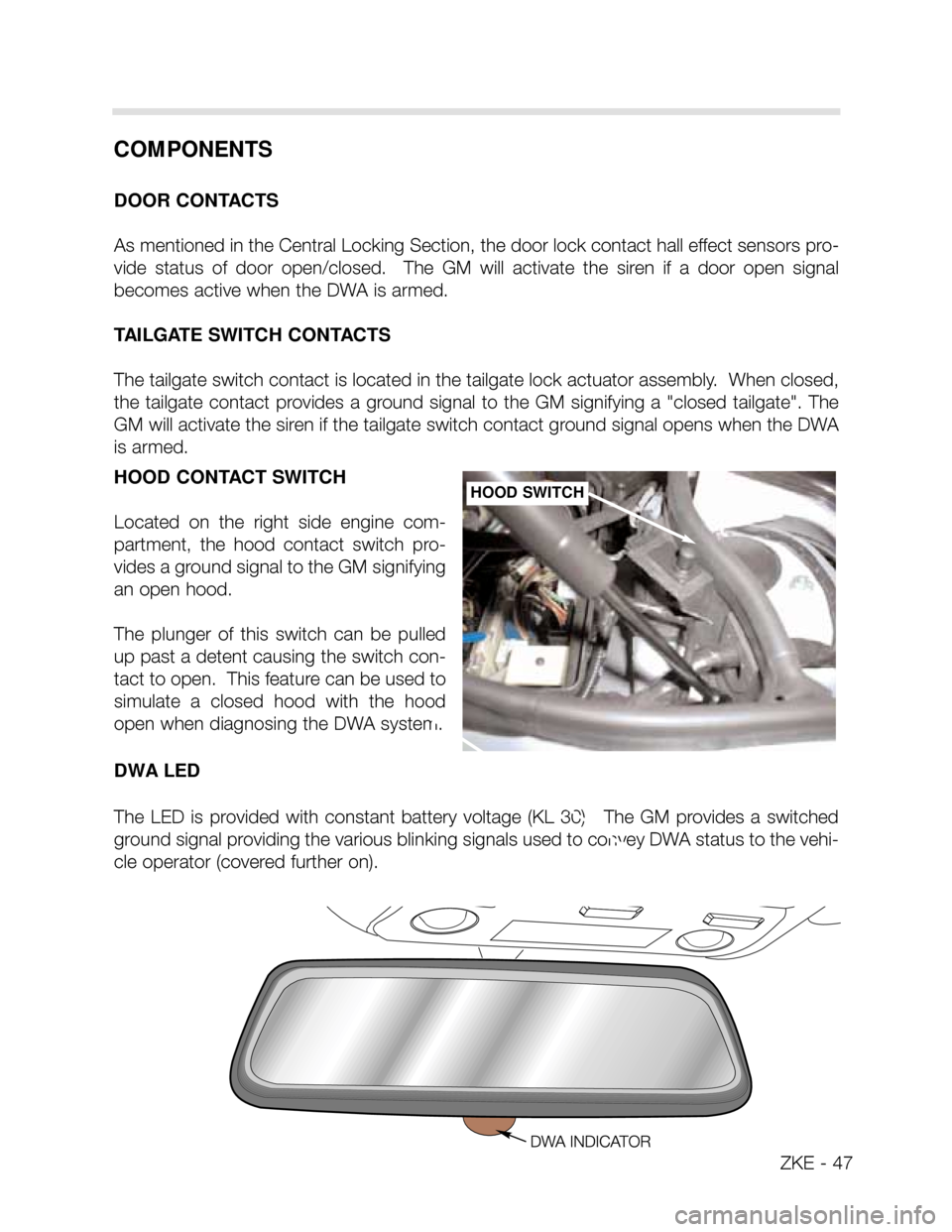
HOOD CONTACT SWITCH
Located on the right side engine com-
partment, the hood contact switch pro-
vides a ground signal to the GM signifying
an open hood.
The plunger of this switch can be pulled
up past a detent causing the switch con-
tact to open. This feature can be used to
simulate a closed hood with the hood
open when diagnosing the DWA system.
DWA LED
The LED is provided with constant battery voltage (KL 30). The GM provides a switched
ground signal providing the various blinking signals used to convey DWA status to the vehi-
cle operator (covered further on).HOOD SWITCH
COMPONENTS
DOOR CONTACTS
As mentioned in the Central Locking Section, the door lock contact hall effect sensors pro-
vide status of door open/closed. The GM will activate the siren if a door open signal
becomes active when the DWA is armed.
TAILGATE SWITCH CONTACTS
The tailgate switch contact is located in the tailgate lock actuator assembly. When closed,
the tailgate contact provides a ground signal to the GM signifying a "closed tailgate". The
GM will activate the siren if the tailgate switch contact ground signal opens when the DWA
is armed.
ZKE - 47
Page 49 of 64
ZKE - 49
INTERIOR PROTECTION (UIS)
The UIS monitors the vehicle interior for motion through ultrasonic sound waves. The UIS
is a combined transmitter and receiver.
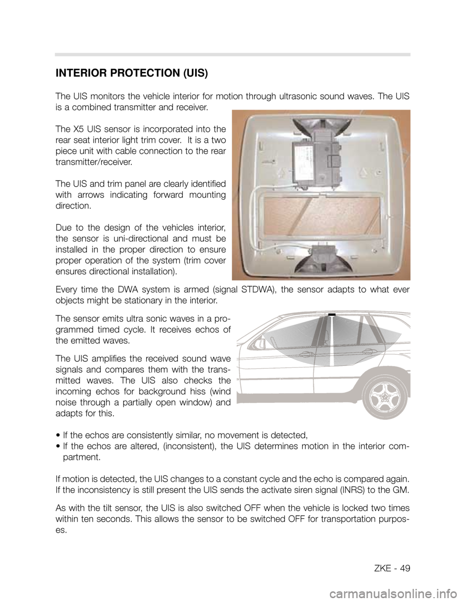
The X5 UIS sensor is incorporated into the
rear seat interior light trim cover. It is a two
piece unit with cable connection to the rear
transmitter/receiver.
The UIS and trim panel are clearly identified
with arrows indicating forward mounting
direction.
Due to the design of the vehicles interior,
the sensor is uni-directional and must be
installed in the proper direction to ensure
proper operation of the system (trim cover
ensures directional installation).
Every time the DWA system is armed (signal STDWA), the sensor adapts to what ever
objects might be stationary in the interior.
The sensor emits ultra sonic waves in a pro-
grammed timed cycle. It receives echos of
the emitted waves.
The UIS amplifies the received sound wave
signals and compares them with the trans-
mitted waves. The UIS also checks the
incoming echos for background hiss (wind
noise through a partially open window) and
adapts for this.
• If the echos are consistently similar, no movement is detected,
• If the echos are altered, (inconsistent), the UIS determines motion in the interior com-
partment.
If motion is detected, the UIS changes to a constant cycle and the echo is compared again.
If the inconsistency is still present the UIS sends the activate siren signal (INRS) to the GM.
As with the tilt sensor, the UIS is also switched OFF when the vehicle is locked two times
within ten seconds. This allows the sensor to be switched OFF for transportation purpos-
es.
Page 51 of 64
ZKE - 51
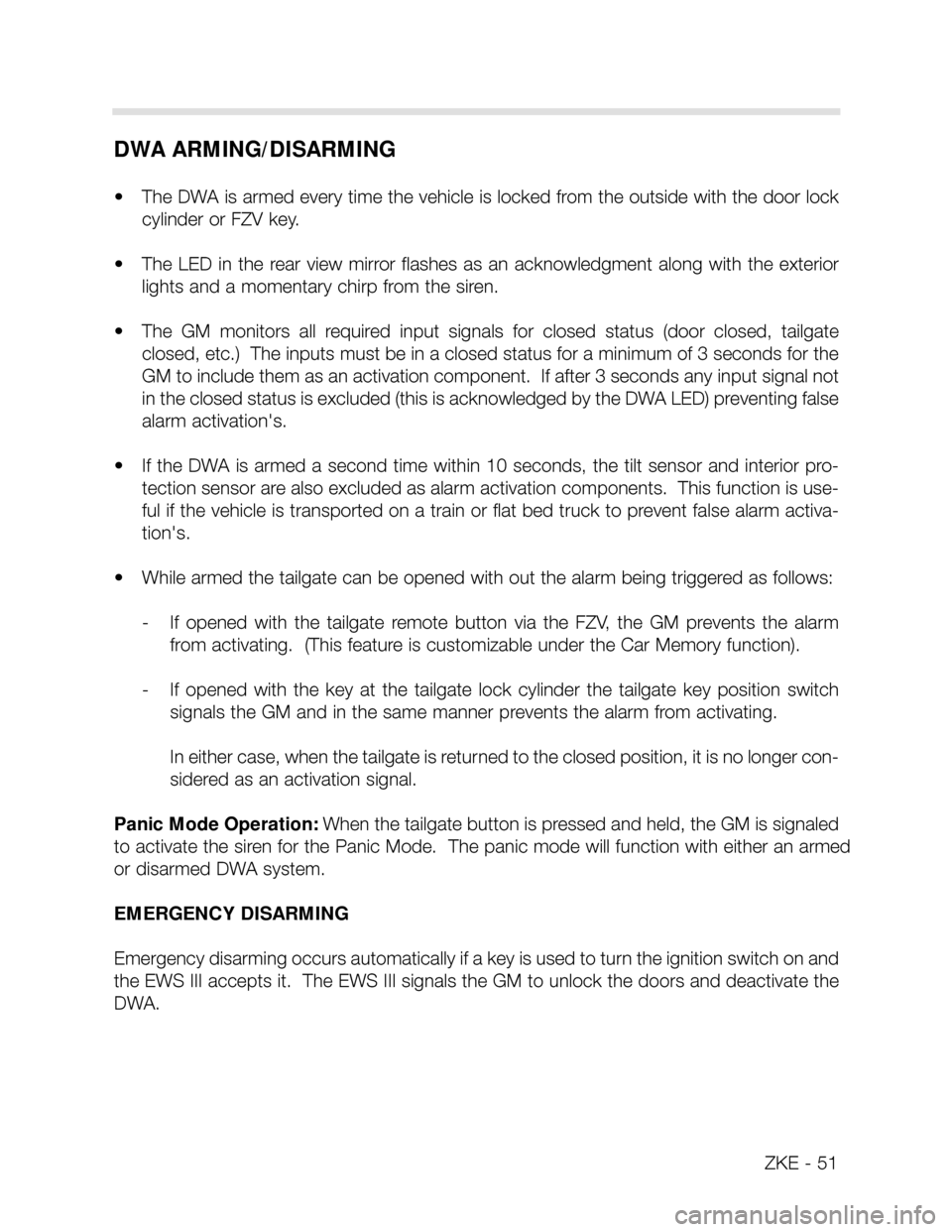
DWA ARMING/DISARMING
• The DWA is armed every time the vehicle is locked from the outside with the door lock
cylinder or FZV key.
• The LED in the rear view mirror flashes as an acknowledgment along with the exterior
lights and a momentary chirp from the siren.
• The GM monitors all required input signals for closed status (door closed, tailgate
closed, etc.) The inputs must be in a closed status for a minimum of 3 seconds for the
GM to include them as an activation component. If after 3 seconds any input signal not
in the closed status is excluded (this is acknowledged by the DWA LED) preventing false
alarm activation's.
• If the DWA is armed a second time within 10 seconds, the tilt sensor and interior pro-
tection sensor are also excluded as alarm activation components. This function is use-
ful if the vehicle is transported on a train or flat bed truck to prevent false alarm activa-
tion's.
• While armed the tailgate can be opened with out the alarm being triggered as follows:
- If opened with the tailgate remote button via the FZV, the GM prevents the alarm
from activating. (This feature is customizable under the Car Memory function).
- If opened with the key at the tailgate lock cylinder the tailgate key position switch
signals the GM and in the same manner prevents the alarm from activating.
In either case, when the tailgate is returned to the closed position, it is no longer con-
sidered as an activation signal.
Panic Mode Operation: When the tailgate button is pressed and held, the GM is signaled
to activate the siren for the Panic Mode. The panic mode will function with either an armed
or disarmed DWA system.
EMERGENCY DISARMING
Emergency disarming occurs automatically if a key is used to turn the ignition switch on and
the EWS III accepts it. The EWS III signals the GM to unlock the doors and deactivate the
DWA.
Page 54 of 64
ZKE -54
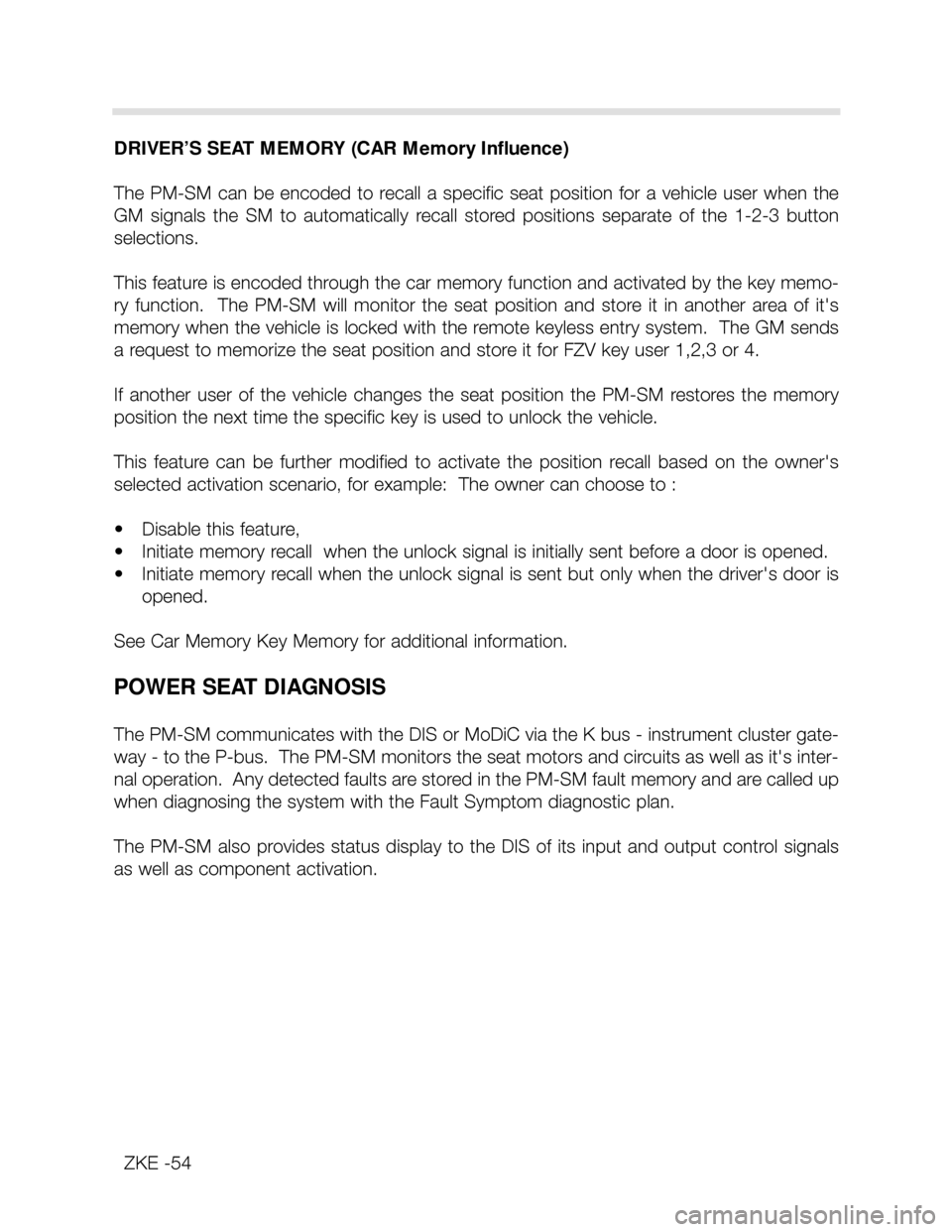
DRIVER’S SEAT MEMORY (CAR Memory Influence)
The PM-SM can be encoded to recall a specific seat position for a vehicle user when the
GM signals the SM to automatically recall stored positions separate of the 1-2-3 button
selections.
This feature is encoded through the car memory function and activated by the key memo-
ry function. The PM-SM will monitor the seat position and store it in another area of it's
memory when the vehicle is locked with the remote keyless entry system. The GM sends
a request to memorize the seat position and store it for FZV key user 1,2,3 or 4.
If another user of the vehicle changes the seat position the PM-SM restores the memory
position the next time the specific key is used to unlock the vehicle.
This feature can be further modified to activate the position recall based on the owner's
selected activation scenario, for example: The owner can choose to :
• Disable this feature,
• Initiate memory recall when the unlock signal is initially sent before a door is opened.
• Initiate memory recall when the unlock signal is sent but only when the driver's door is
opened.
See Car Memory Key Memory for additional information.
POWER SEAT DIAGNOSIS
The PM-SM communicates with the DIS or MoDiC via the K bus - instrument cluster gate-
way - to the P-bus. The PM-SM monitors the seat motors and circuits as well as it's inter-
nal operation. Any detected faults are stored in the PM-SM fault memory and are called up
when diagnosing the system with the Fault Symptom diagnostic plan.
The PM-SM also provides status display to the DIS of its input and output control signals
as well as component activation.
Page 55 of 64
MIRROR OPERATION
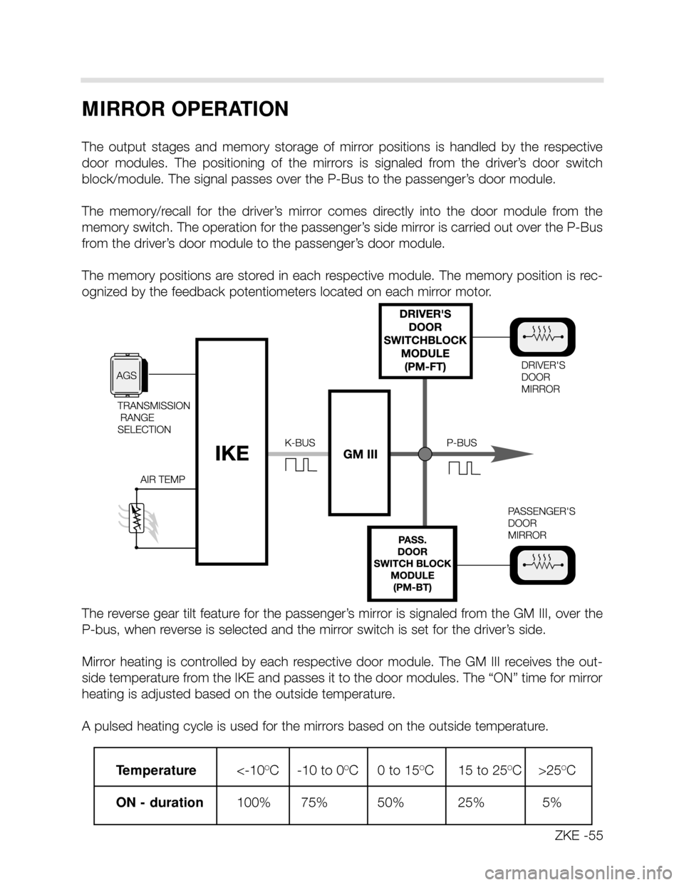
The output stages and memory storage of mirror positions is handled by the respective
door modules. The positioning of the mirrors is signaled from the driver’s door switch
block/module. The signal passes over the P-Bus to the passenger’s door module.
The memory/recall for the driver’s mirror comes directly into the door module from the
memory switch. The operation for the passenger’s side mirror is carried out over the P-Bus
from the driver’s door module to the passenger’s door module.
The memory positions are stored in each respective module. The memory position is rec-
ognized by the feedback potentiometers located on each mirror motor.
The reverse gear tilt feature for the passenger’s mirror is signaled from the GM III, over the
P-bus, when reverse is selected and the mirror switch is set for the driver’s side.
Mirror heating is controlled by each respective door module. The GM III receives the out-
side temperature from the IKE and passes it to the door modules. The “ON” time for mirror
heating is adjusted based on the outside temperature.
A pulsed heating cycle is used for the mirrors based on the outside temperature.
ZKE -55
Temperature<-10OC -10 to 0OC 0 to 15OC 15 to 25OC >25OC
ON - duration 100% 75% 50% 25% 5%
Page 62 of 64
62
SLEEP MODE
To lower the constant battery draw when the vehicle is parked, The complete ZKE system
will go into the “Sleep Mode” 16 minutes after the ignition has been switched off and no
further ZKE function is active.
Approximate X5 Battery draw: • Ignition switch off = approx 750 mA.
• One minute after = approx. 560 mA.
• After 16 minutes (sleep mode) = approx. 18 mA.
All modules in the ZKE system will go into the sleep mode. The P-Bus remains active, how-
ever no data transfer takes place until a wake-up request is received. The general module,
door modules or keyless remote module can wake the system up and put the ZKE back
on line. The K-Bus is not active in the sleep mode, however the GM III of Remote Entry
Module can put the K-Bus back on-line with a wake-up request.
SLEEP MODE CRITERIA: KL R, 15 OFF and no further function activated for 16 minutes.
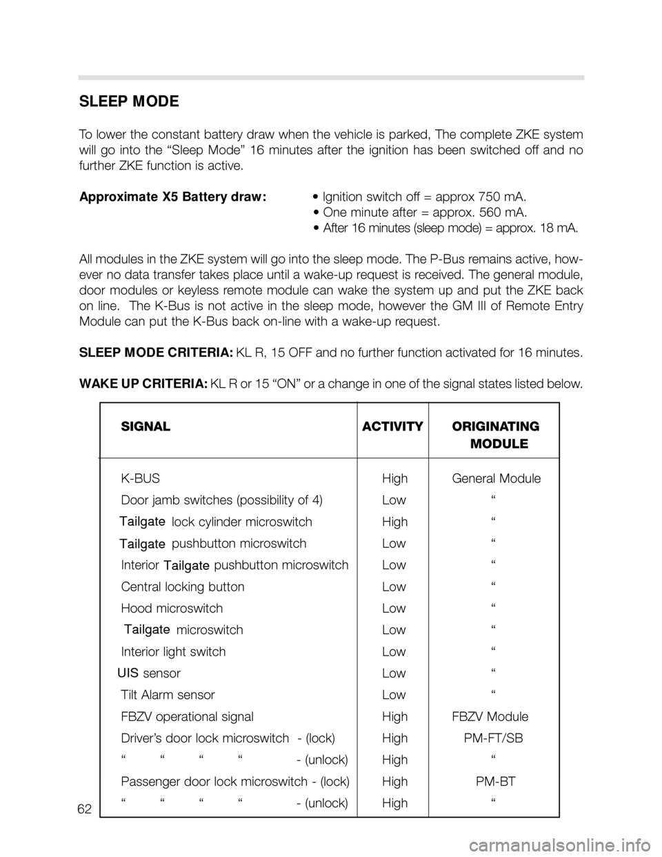
WAKE UP CRITERIA: KL R or 15 “ON” or a change in one of the signal states listed below.
SIGNAL ACTIVITY ORIGINATING
MODULE
K-BUS High General Module
Door jamb switches (possibility of 4) Low “
Trunk lid lock cylinder microswitch High “
Trunk lid pushbutton microswitch Low “
Interior Trunk lid pushbutton microswitch Low “
Central locking button Low “
Hood microswitch Low “
Trunk Lid microswitch Low “
Interior light switch Low “
FIS sensor Low “
Tilt Alarm sensor Low “
FBZV operational signal High FBZV Module
Driver’s door lock microswitch - (lock) High PM-FT/SB
““““ - (unlock) High “
Passenger door lock microswitch - (lock) High PM-BT
““““ - (unlock) High “
Tailgate
Tailgate
Tailgate
Tailgate
UIS