engine BMW X5 2000 E53 Central Body Electronics Workshop Manual
[x] Cancel search | Manufacturer: BMW, Model Year: 2000, Model line: X5, Model: BMW X5 2000 E53Pages: 64, PDF Size: 4.03 MB
Page 6 of 64

WINDSHIELD WIPING/WASHING
• The GM III controls all of the windshield wiping/washer and headlight washing functions.
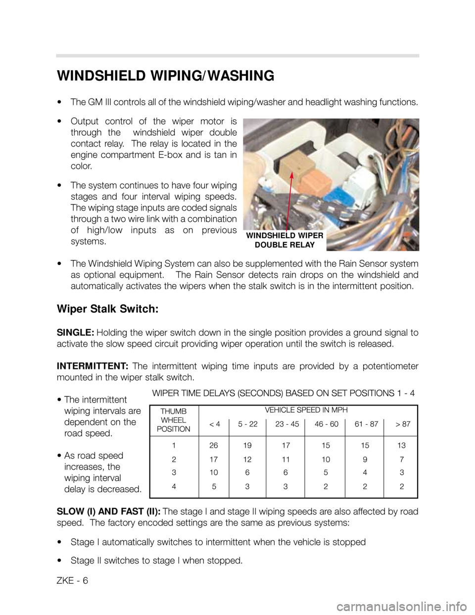
• Output control of the wiper motor is
through the windshield wiper double
contact relay. The relay is located in the
engine compartment E-box and is tan in
color.
• The system continues to have four wiping
stages and four interval wiping speeds.
The wiping stage inputs are coded signals
through a two wire link with a combination
of high/low inputs as on previous
systems.
• The Windshield Wiping System can also be supplemented with the Rain Sensor system
as optional equipment. The Rain Sensor detects rain drops on the windshield and
automatically activates the wipers when the stalk switch is in the intermittent position.
Wiper Stalk Switch:
SINGLE: Holding the wiper switch down in the single position provides a ground signal to
activate the slow speed circuit providing wiper operation until the switch is released.
INTERMITTENT: The intermittent wiping time inputs are provided by a potentiometer
mounted in the wiper stalk switch.
• The intermittent
wiping intervals are
dependent on the
road speed.
• As road speed
increases, the
wiping interval
delay is decreased.
SLOW (I) AND FAST (II): The stage I and stage II wiping speeds are also affected by road
speed. The factory encoded settings are the same as previous systems:
• Stage I automatically switches to intermittent when the vehicle is stopped
• Stage II switches to stage I when stopped.
ZKE - 6
WINDSHIELD WIPER
DOUBLE RELAY
Page 8 of 64

ZKE - 8
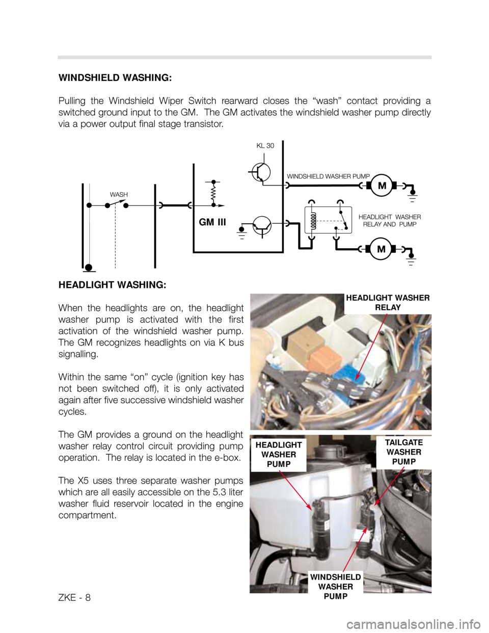
WINDSHIELD WASHING:
Pulling the Windshield Wiper Switch rearward closes the “wash” contact providing a
switched ground input to the GM. The GM activates the windshield washer pump directly
via a power output final stage transistor.
HEADLIGHT WASHING:
When the headlights are on, the headlight
washer pump is activated with the first
activation of the windshield washer pump.
The GM recognizes headlights on via K bus
signalling.
Within the same “on” cycle (ignition key has
not been switched off), it is only activated
again after five successive windshield washer
cycles.
The GM provides a ground on the headlight
washer relay control circuit providing pump
operation. The relay is located in the e-box.
The X5 uses three separate washer pumps
which are all easily accessible on the 5.3 liter
washer fluid reservoir located in the engine
compartment.
GM III
HEADLIGHT WASHER
RELAY
HEADLIGHT
WASHER
PUMP
WINDSHIELD
WASHER
PUMP
TAILGATE
WASHER
PUMP
Page 40 of 64

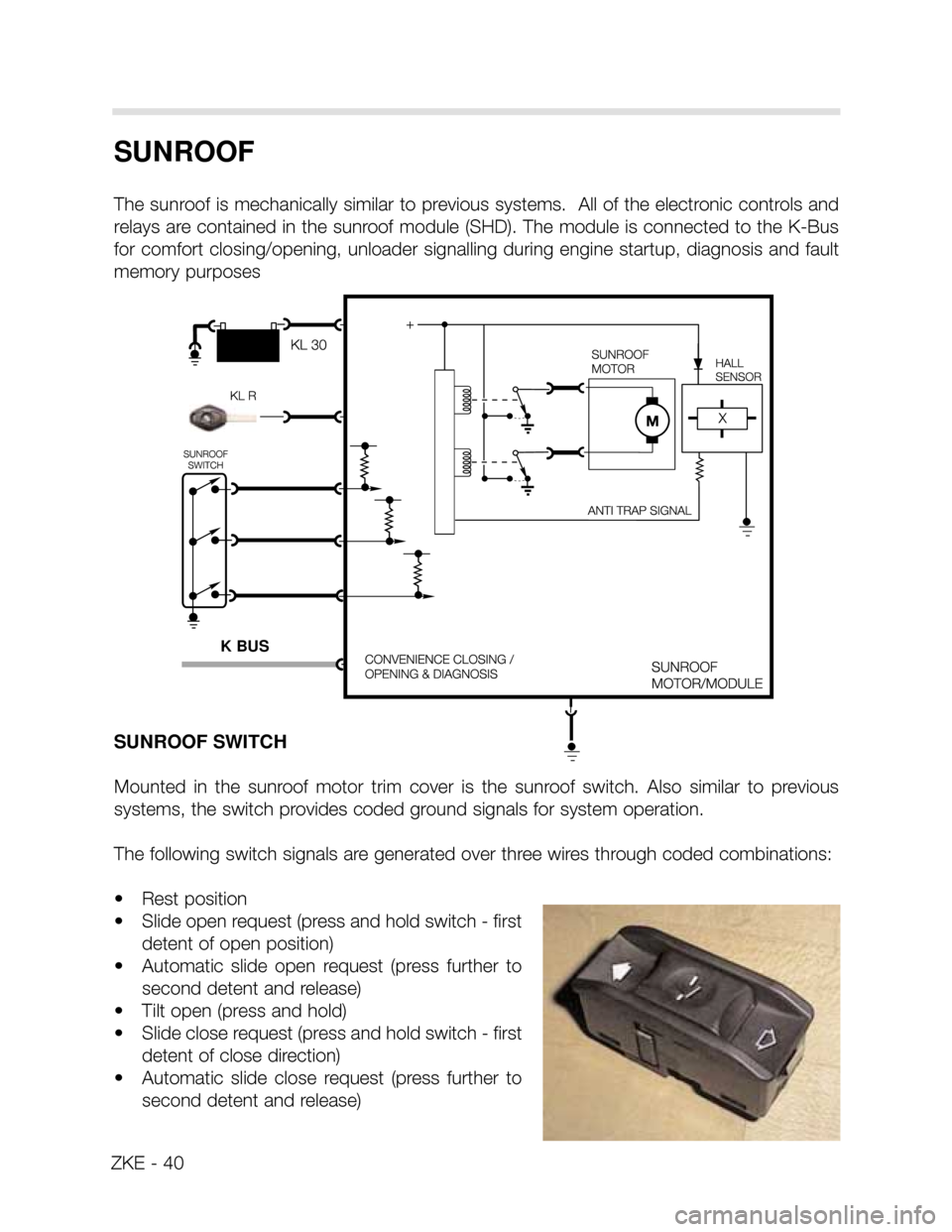
SUNROOF
The sunroof is mechanically similar to previous systems. All of the electronic controls and
relays are contained in the sunroof module (SHD). The module is connected to the K-Bus
for comfort closing/opening, unloader signalling during engine startup, diagnosis and fault
memory purposes
SUNROOF SWITCH
Mounted in the sunroof motor trim cover is the sunroof switch. Also similar to previous
systems, the switch provides coded ground signals for system operation.
The following switch signals are generated over three wires through coded combinations:
• Rest position
• Slide open request (press and hold switch - first
detent of open position)
• Automatic slide open request (press further to
second detent and release)
• Tilt open (press and hold)
• Slide close request (press and hold switch - first
detent of close direction)
• Automatic slide close request (press further to
second detent and release)
ZKE - 40
K BUS
Page 47 of 64

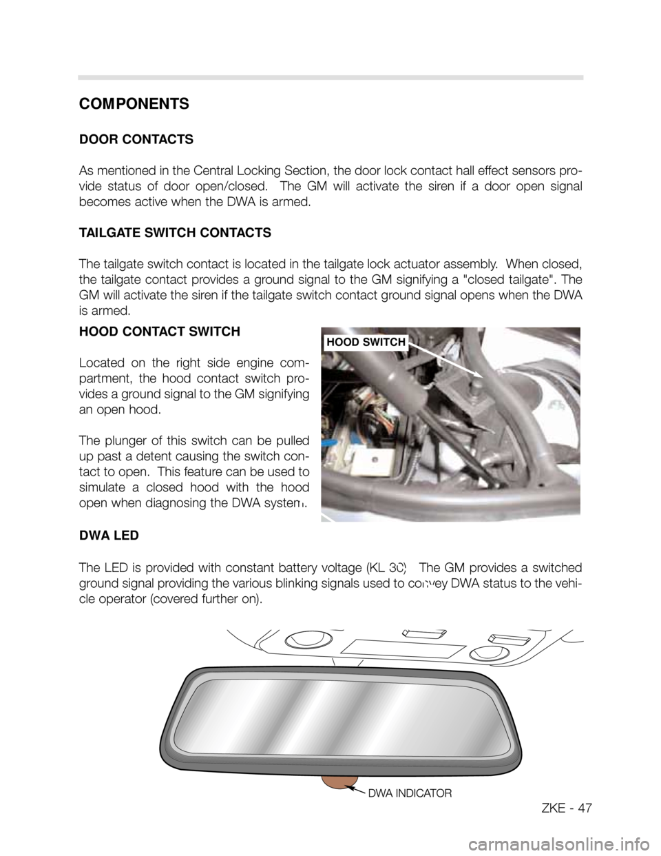
HOOD CONTACT SWITCH
Located on the right side engine com-
partment, the hood contact switch pro-
vides a ground signal to the GM signifying
an open hood.
The plunger of this switch can be pulled
up past a detent causing the switch con-
tact to open. This feature can be used to
simulate a closed hood with the hood
open when diagnosing the DWA system.
DWA LED
The LED is provided with constant battery voltage (KL 30). The GM provides a switched
ground signal providing the various blinking signals used to convey DWA status to the vehi-
cle operator (covered further on).HOOD SWITCH
COMPONENTS
DOOR CONTACTS
As mentioned in the Central Locking Section, the door lock contact hall effect sensors pro-
vide status of door open/closed. The GM will activate the siren if a door open signal
becomes active when the DWA is armed.
TAILGATE SWITCH CONTACTS
The tailgate switch contact is located in the tailgate lock actuator assembly. When closed,
the tailgate contact provides a ground signal to the GM signifying a "closed tailgate". The
GM will activate the siren if the tailgate switch contact ground signal opens when the DWA
is armed.
ZKE - 47