BMW X5 2001 E53 DSC System User Guide
Manufacturer: BMW, Model Year: 2001, Model line: X5, Model: BMW X5 2001 E53Pages: 24, PDF Size: 1.77 MB
Page 11 of 24
11
DYNAMIC BRAKING SYSTEM
The dynamic braking system is designed to enhance the braking control of the DSC for the
driver of the vehicle. The dynamic braking control and maximum braking control are func-
tions that are programmed into the control electronics of the DSC with no additional hard-
ware changes.
DYNAMIC BRAKING CONTROL (DBC)
The DBC function is designed to provide the maximum braking force available during rapid
(panic) braking situations. The DSC control module looks at the inputs from the brake pedal
switch and the signal from the brake pressure sensor on the master cylinder. The criteria
for activation of DBC is how rapidly is the brake pressure built up with the brake pedal
depressed. The total criteria required for DBC activation includes:
• Brake switch ON
• Brake pressure build up > threshold value
• Vehicle road speed > 5MPH
• Vehicle not in reverse
• Not all wheels in ABS regulation
If the threshold for DBC activation is achieved, the DSC control module will activate a pres-
sure build up regulation phase through the hydraulic unit. The pressure at all wheels is
increased up to the ABS regulation point. This occurs even if the driver does not achieve
the ABS regulation point with the pedal.
The rear axle brakes are controlled with select-low regulation and the front axle brakes are
controlled individually. ABS regulation will continue until the driver releases the pedal and
the pressure in the master cylinder drops below the threshold value stored in the DSC con-
trol module.
MAXIMUM BRAKE CONTROL (MBC)
The MBC function is also designed to enhance a driver initiated braking procedure. The
MBC will build up the pressure in the rear brake circuit when the front brakes are already in
an ABS regulation cycle. The additional braking pressure at the rear wheels will shorten the
stopping distance. The following criteria must be met before the DSC control module will
activate MBC:
• Both front wheel brakes in ABS regulation
• Vehicle speed > 5 MPH
• Vehicle not in reverse
• DBC and pressure sensor initialization test OK
• Rear wheels not in ABS regulation
Page 12 of 24
12
DSC NEW FUNCTIONS
HILL DECENT CONTROL (HDC)
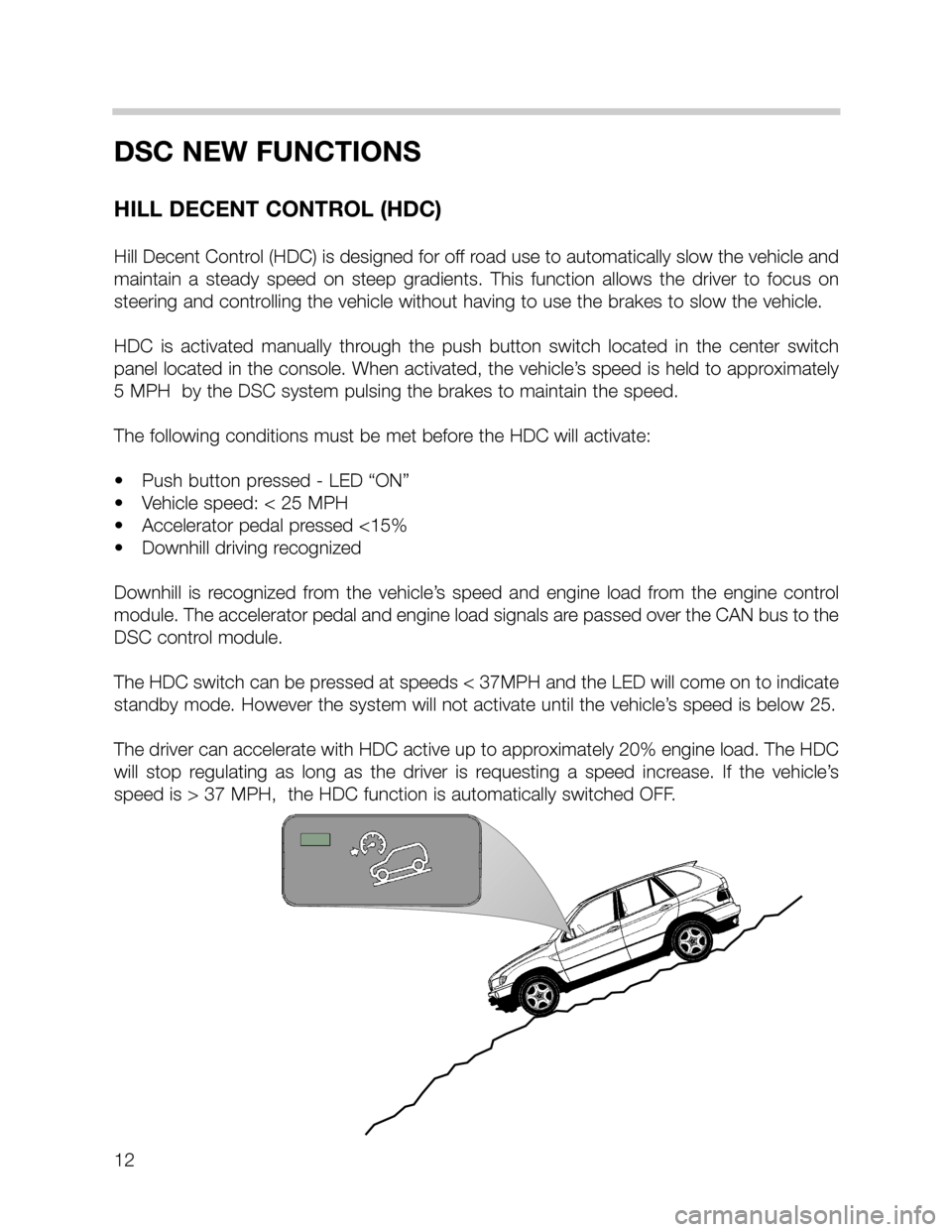
Hill Decent Control (HDC) is designed for off road use to automatically slow the vehicle and
maintain a steady speed on steep gradients. This function allows the driver to focus on
steering and controlling the vehicle without having to use the brakes to slow the vehicle.
HDC is activated manually through the push button switch located in the center switch
panel located in the console. When activated, the vehicle’s speed is held to approximately
5 MPH by the DSC system pulsing the brakes to maintain the speed.
The following conditions must be met before the HDC will activate:
• Push button pressed - LED “ON”
• Vehicle speed: < 25 MPH
• Accelerator pedal pressed <15%
• Downhill driving recognized
Downhill is recognized from the vehicle’s speed and engine load from the engine control
module. The accelerator pedal and engine load signals are passed over the CAN bus to the
DSC control module.
The HDC switch can be pressed at speeds < 37MPH and the LED will come on to indicate
standby mode. However the system will not activate until the vehicle’s speed is below 25.
The driver can accelerate with HDC active up to approximately 20% engine load. The HDC
will stop regulating as long as the driver is requesting a speed increase. If the vehicle’s
speed is > 37 MPH, the HDC function is automatically switched OFF.
Page 13 of 24
13
DSC - NEW FUNCTIONS
AUTOMATIC DIFFERENTIAL BRAKE (ADB)
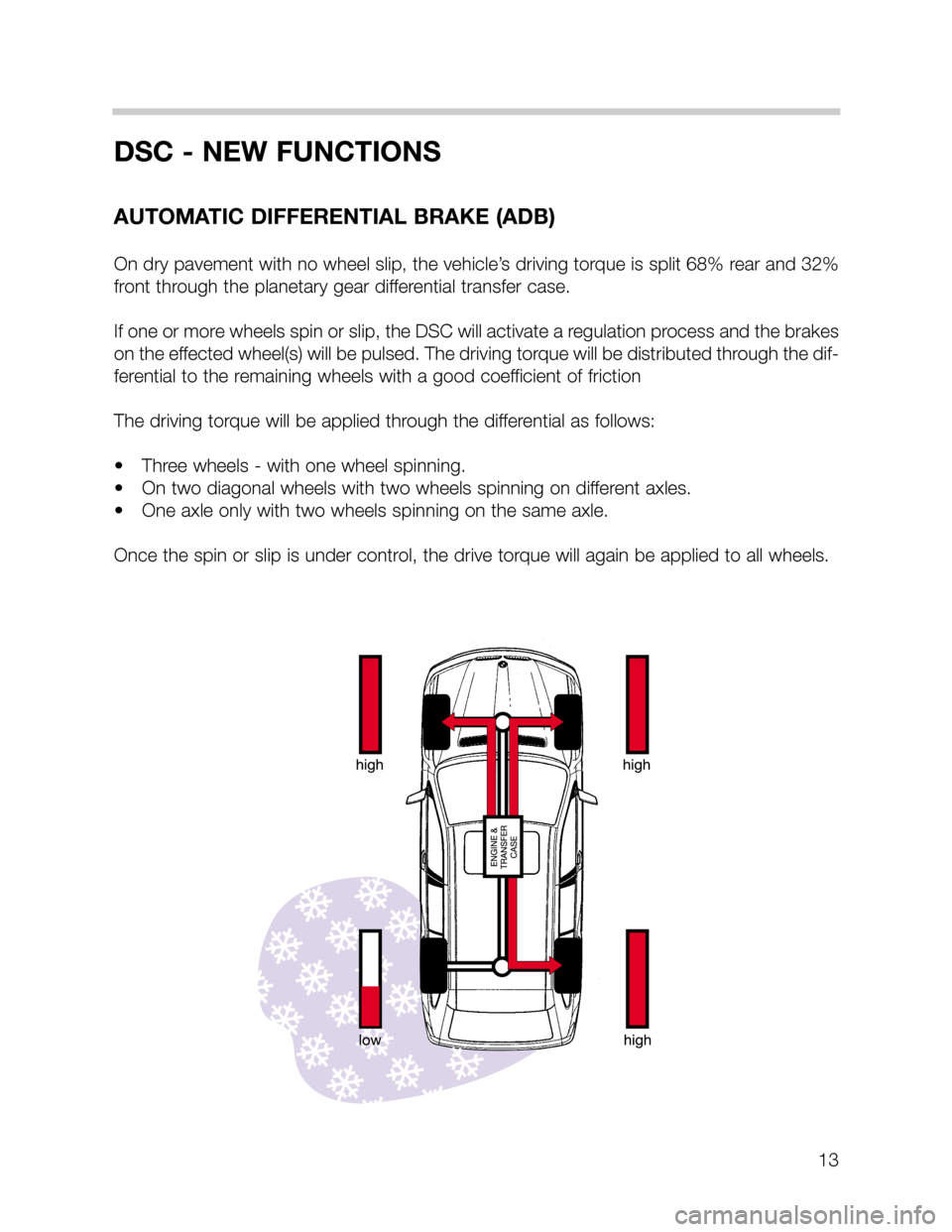
On dry pavement with no wheel slip, the vehicle’s driving torque is split 68% rear and 32%
front through the planetary gear differential transfer case.
If one or more wheels spin or slip, the DSC will activate a regulation process and the brakes
on the effected wheel(s) will be pulsed. The driving torque will be distributed through the dif-
ferential to the remaining wheels with a good coefficient of friction
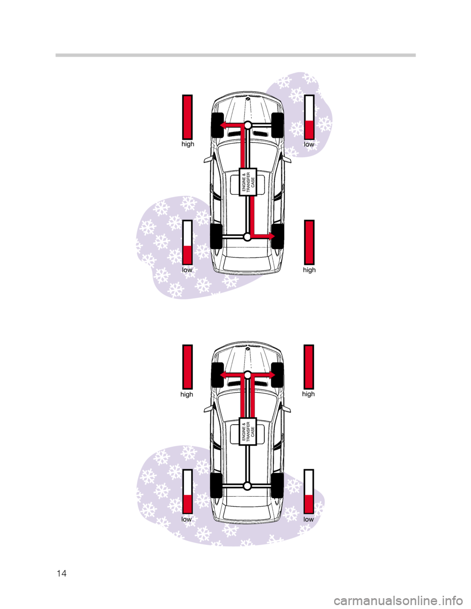
The driving torque will be applied through the differential as follows:
• Three wheels - with one wheel spinning.
• On two diagonal wheels with two wheels spinning on different axles.
• One axle only with two wheels spinning on the same axle.
Once the spin or slip is under control, the drive torque will again be applied to all wheels.
Page 14 of 24
14
Page 15 of 24
15
DSC - NEW FEATURE
TRACTION CONTROL
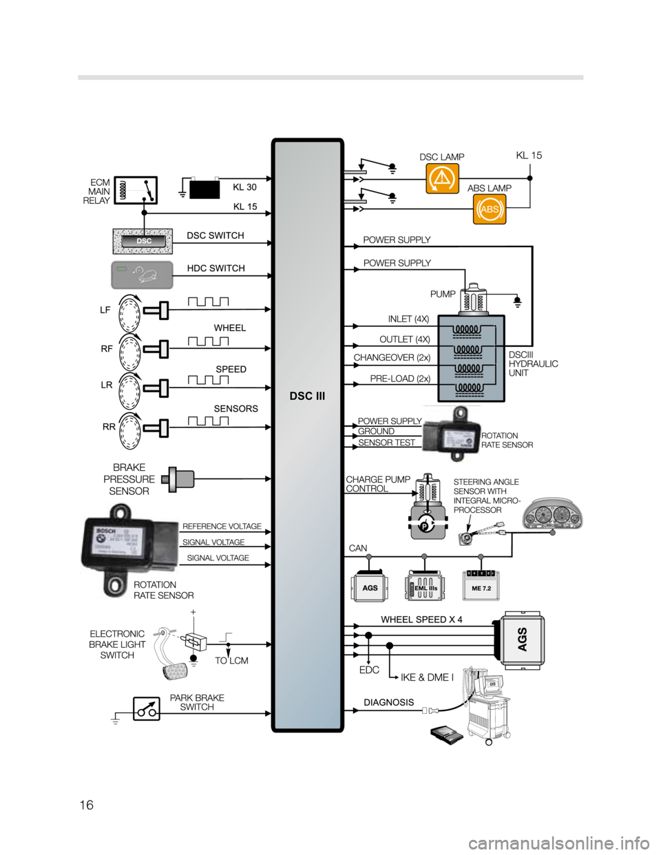
The traction control feature of the DSC III on the X5 cannot be switched OFF with the DSC
switch. Pressing the button will only switch off the dynamic stability control function of the
DSC.
The traction control feature is needed at all times to provide anti-spin control especially
when driving the vehicle off road. The DSC warning lamp in the instrument cluster will still
come on when the system is switched off manually or there is a fault in the system.
Off road traction control or HDC regulation places an additional load on the brakes. To pre-
vent overheating of the brakes and rotors, the temperature of the rotors is calculated over
time from the road speed and amount of brake application. If the temperature of one or
more rotors goes above 600o
C, the traction control or HDC function for that wheel will be
cancelled temporarily. Once the temperature of the rotor goes below 500o
C, the traction
application will be re-activated.
The normal braking function (including ABS) is always active at any temperatures.
DSC - NEW FEATURE
OFF-ROAD ABS Control Module Programming
The programming for ABS regulation have changed to allow a higher threshold for ABS reg-
ulation when driving off-road in loose gravel or dirt. A locked wheel is more effective in slow-
ing or stopping the vehicle because of the wedge that is built up in front of the tire.
The programming in the DSC control module allows one or both front wheel(s) to lock up
to a speed of 12 MPH as long as the vehicle is traveling straight ahead. If the DSC control
module receives a signal from the steering angle sensor indicating a turn, ABS regulation
will activate to prevent the lock and allow the vehicle to be steered.
Page 16 of 24
16
Page 17 of 24
17
Page 18 of 24
18
COMPONENTS
CONTROL MODULE HYDRAULIC UNIT
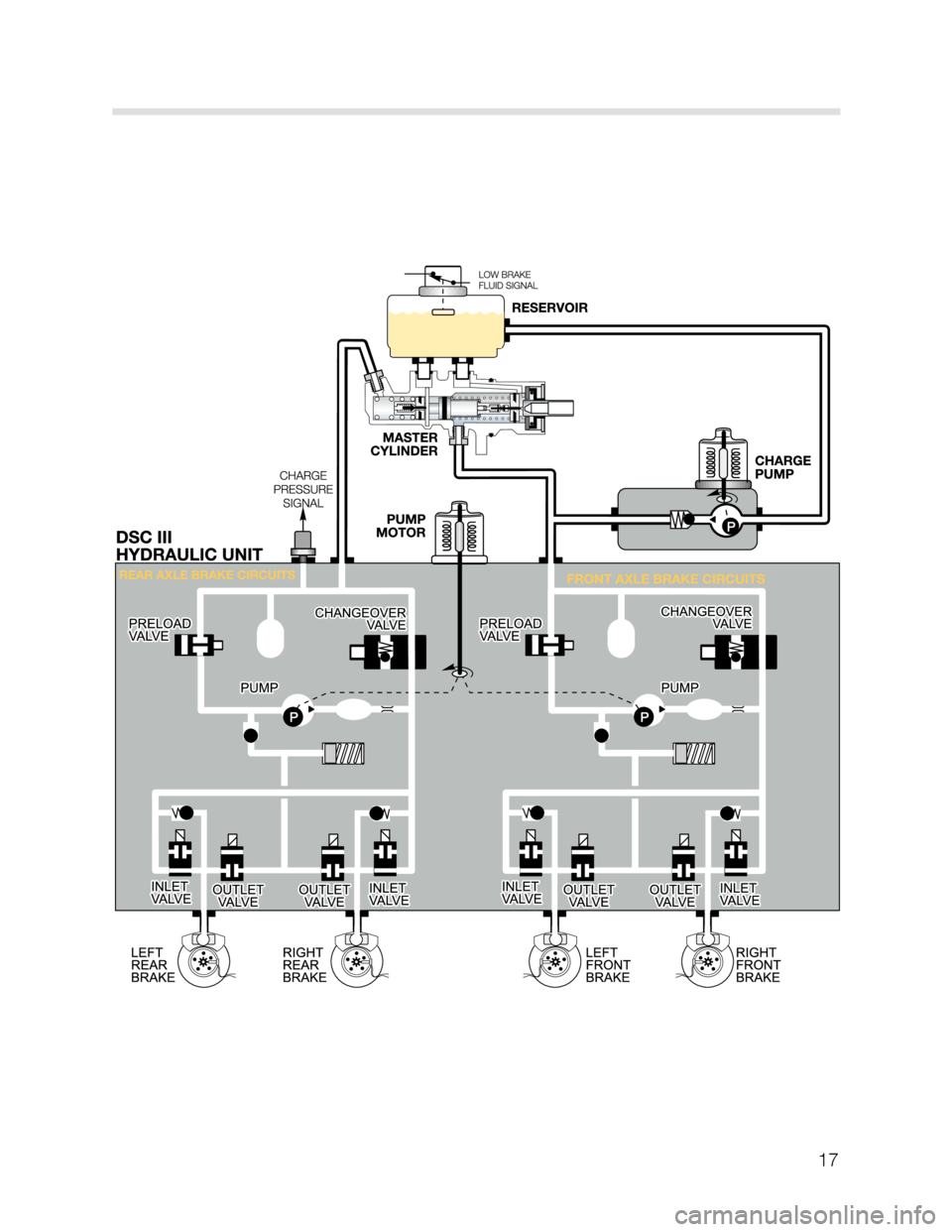
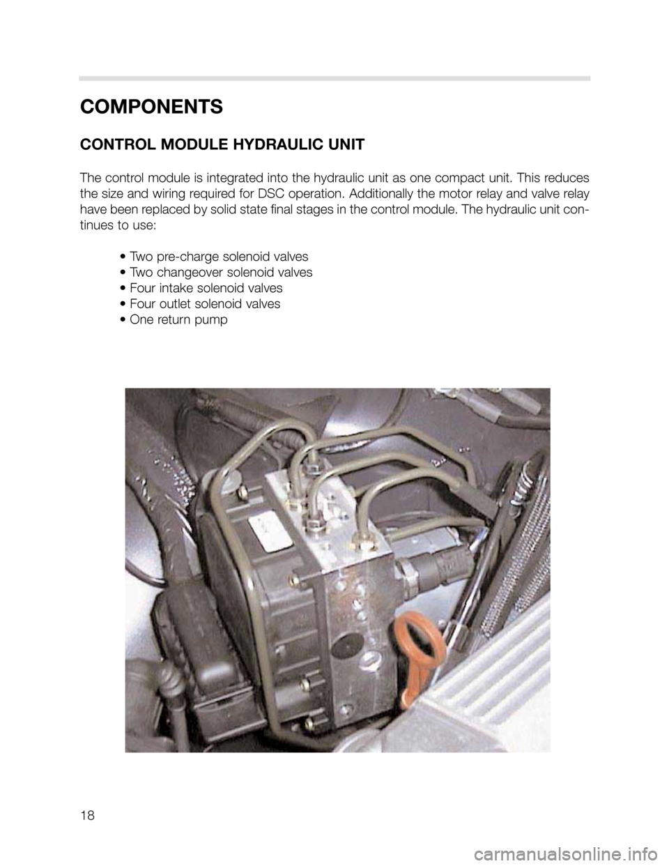
The control module is integrated into the hydraulic unit as one compact unit. This reduces
the size and wiring required for DSC operation. Additionally the motor relay and valve relay
have been replaced by solid state final stages in the control module. The hydraulic unit con-
tinues to use:
• Two pre-charge solenoid valves
• Two changeover solenoid valves
• Four intake solenoid valves
• Four outlet solenoid valves
• One return pump
Page 19 of 24
19
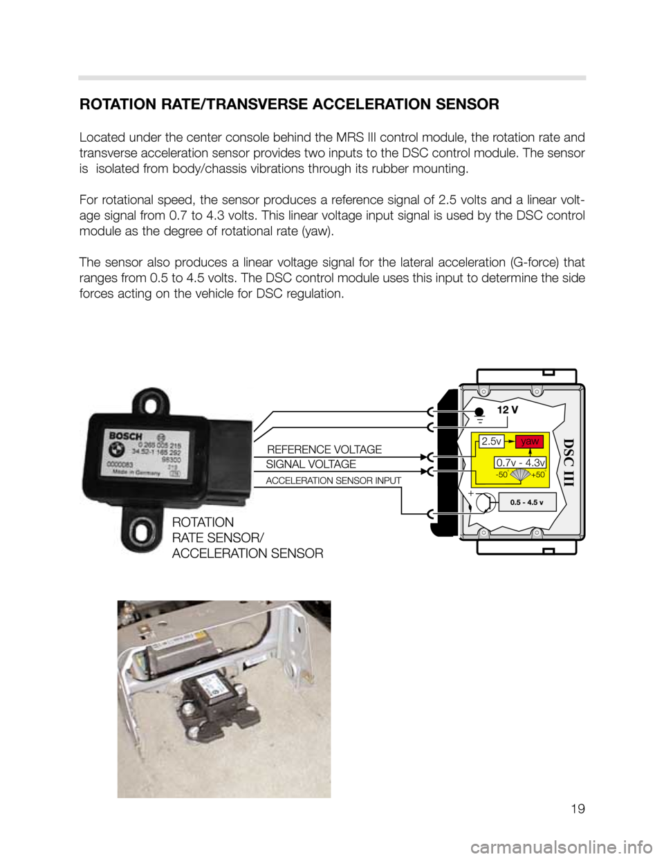
ROTATION RATE/TRANSVERSE ACCELERATION SENSOR
Located under the center console behind the MRS III control module, the rotation rate and
transverse acceleration sensor provides two inputs to the DSC control module. The sensor
is isolated from body/chassis vibrations through its rubber mounting.
For rotational speed, the sensor produces a reference signal of 2.5 volts and a linear volt-
age signal from 0.7 to 4.3 volts. This linear voltage input signal is used by the DSC control
module as the degree of rotational rate (yaw).
The sensor also produces a linear voltage signal for the lateral acceleration (G-force) that
ranges from 0.5 to 4.5 volts. The DSC control module uses this input to determine the side
forces acting on the vehicle for DSC regulation.
Page 20 of 24
20
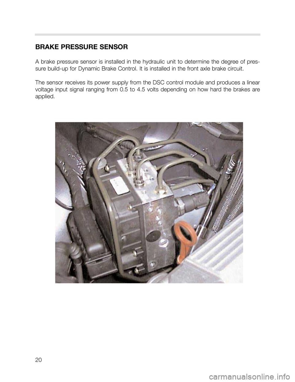
BRAKE PRESSURE SENSOR
A brake pressure sensor is installed in the hydraulic unit to determine the degree of pres-
sure build-up for Dynamic Brake Control. It is installed in the front axle brake circuit.
The sensor receives its power supply from the DSC control module and produces a linear
voltage input signal ranging from 0.5 to 4.5 volts depending on how hard the brakes are
applied.