relay BMW X5 2001 E53 M62TU Engine Workshop Manual
[x] Cancel search | Manufacturer: BMW, Model Year: 2001, Model line: X5, Model: BMW X5 2001 E53Pages: 37, PDF Size: 3.87 MB
Page 19 of 37
19
INPUT SIGNALS/COMPONENTS
CAMSHAFT POSITION SENSORS
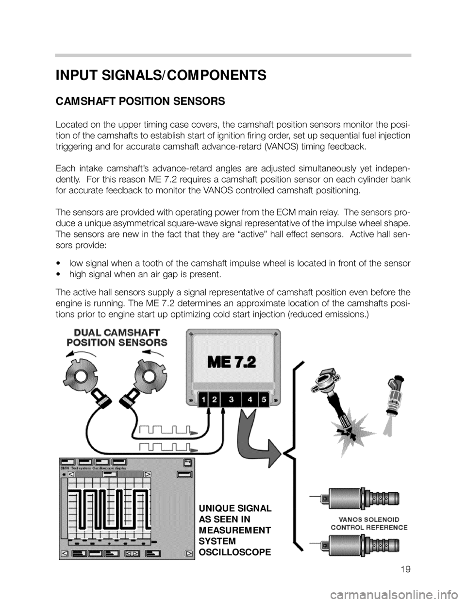
Located on the upper timing case covers, the camshaft position sensors monitor the posi-
tion of the camshafts to establish start of ignition firing order, set up sequential fuel injection
triggering and for accurate camshaft advance-retard (VANOS) timing feedback.
Each intake camshaft’s advance-retard angles are adjusted simultaneously yet indepen-
dently. For this reason ME 7.2 requires a camshaft position sensor on each cy linder bank
for accurate feedback to monitor the VANOS controlled camshaft positioning.
The sensors are provided with operating power from the ECM main relay. The sensors pro-
duce a unique asymmetrical square-wave signal representative of the impulse wheel shape.
The sensors are new in the fact that they are “active” hall effect sensors. Active hall sen-
sors provide:
• low signal when a tooth of the camshaft impulse wheel is located in front of the sensor
• high signal when an air gap is present.
The active hall sensors supply a signal representative of camshaft position even before the
engine is running. The ME 7.2 determines an approximate location of the camshafts posi-
tions prior to engine start up optimizing cold start injection (reduced emissions.)
UNIQUE SIGNAL
AS SEEN IN
MEASUREMENT
SYSTEM
OSCILLOSCOPE
Page 20 of 37
20
HOT FILM AIR MASS SENSOR (HFM 5)
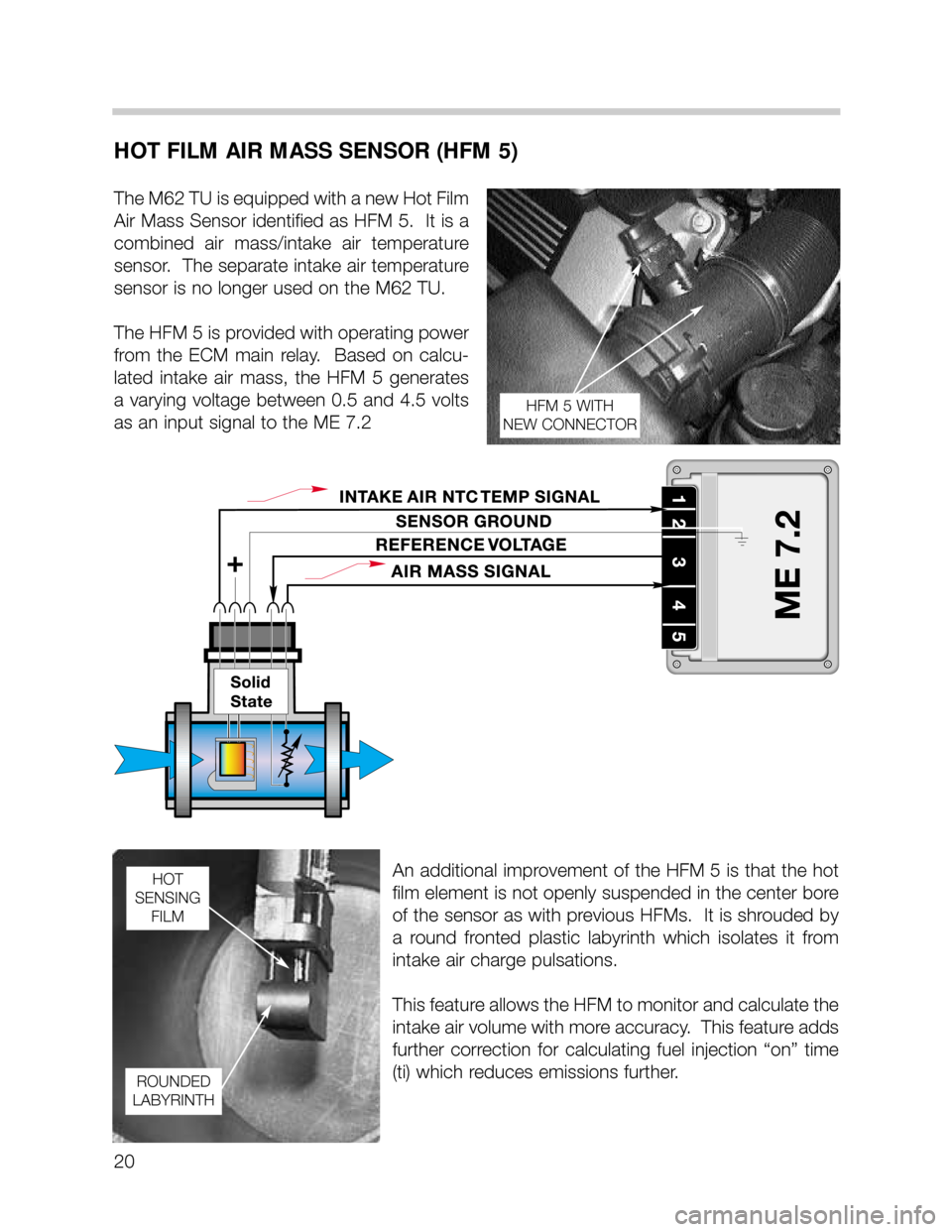
The M62 TU is equipped with a new Hot Film
Air Mass Sensor identified as HFM 5. It is a
combined air mass/intake air temperature
sensor. The separate intake air temperature
sensor is no longer used on the M62 TU.
The HFM 5 is provided with operating power
from the ECM main relay. Based on calcu-
lated intake air mass, the HFM 5 generates
a varying voltage between 0.5 and 4.5 volts
as an input signal to the ME 7.2
An additional improvement of the HFM 5 is that the hot
film element is not openly suspended in the center bore
of the sensor as with previous HFMs. It is shrouded by
a round fronted plastic labyrinth which isolates it from
intake air charge pulsations.
This feature allows the HFM to monitor and calculate the
intake air volume with more accuracy. This feature adds
further correction for calculating fuel injection “on” time
(ti) which reduces emissions further.
HFM 5 WITH
NEW CONNECTOR
HOT
SENSING
FILM
ROUNDED
LABYRINTH
Page 27 of 37
27
OUTPUT CONTROL FUNCTIONS
FUEL PUMP RELAY CONTROL
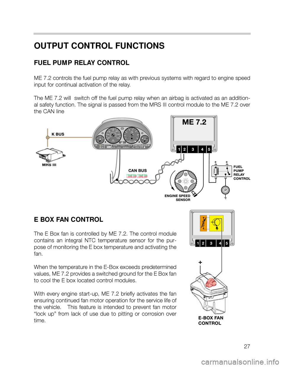
ME 7.2 controls the fuel pump relay as with previous systems with regard to engine speed
input for continual activation of the relay.
The ME 7.2 will switch off the fuel pump relay when an airbag is activated as an addition-
al safety function. The signal is passed from the MRS III control module to the ME 7.2 over
the CAN line
E BOX FAN CONTROL
The E Box fan is controlled by ME 7.2. The control module
contains an integral NTC temperature sensor for the pur-
pose of monitoring the E box temperature and activating the
fan.
When the temperature in the E-Box exceeds predetermined
values, ME 7.2 provides a switched ground for the E Box fan
to cool the E box located control modules.
With every engine start-up, ME 7.2 briefly activates the fan
ensuring continued fan motor operation for the service life of
the vehicle. This feature is intended to prevent fan motor
“lock up” from lack of use due to pitting or corrosion over
time.
Page 28 of 37
28
SECONDARY AIR INJECTION
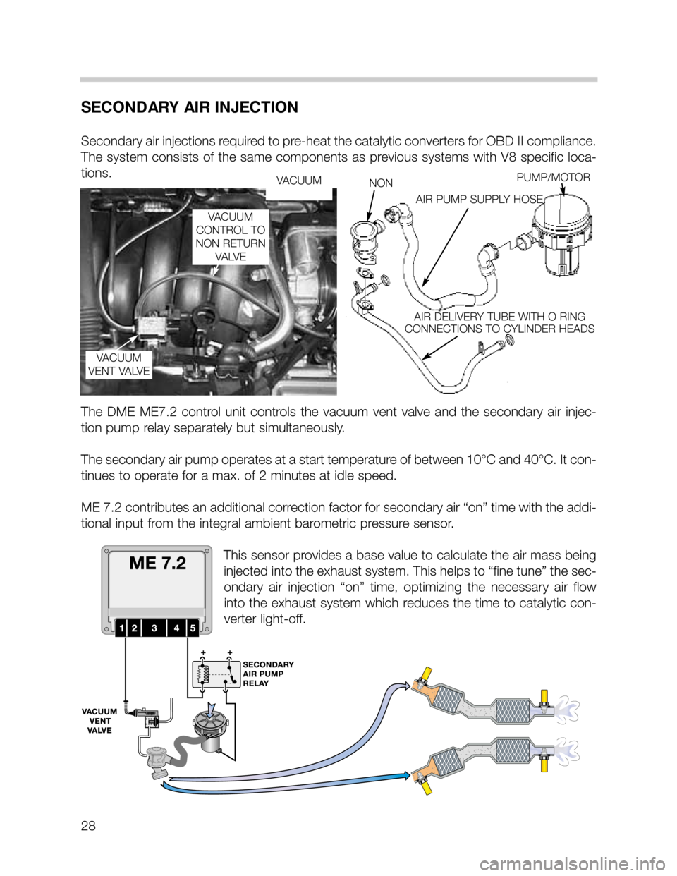
Secondary air injections required to pre-heat the catalytic converters for OBD II compliance.
The system consists of the same components as previous systems with V8 specific loca-
tions.
The DME ME7.2 control unit controls the vacuum vent valve and the secondary air injec-
tion pump relay separately but simultaneously.
The secondary air pump operates at a start temperature of between 10°C and 40°C. It con-
tinues to operate for a max. of 2 minutes at idle speed.
ME 7.2 contributes an additional correction factor for secondary air “on” time with the addi-
tional input from the integral ambient barometric pressure sensor.
This sensor provides a base value to calculate the air mass being
injected into the exhaust system. This helps to “fine tune” the sec-
ondary air injection “on” time, optimizing the necessary air flow
into the exhaust system which reduces the time to catalytic con-
verter light-off.
VACUUM
VACUUM
VENT VALVENONPUMP/MOTOR
AIR PUMP SUPPLY HOSE
AIR DELIVERY TUBE WITH O RING
CONNECTIONS TO CYLINDER HEADS
VACUUM
CONTROL TO
NON RETURN
VA LV E
Page 34 of 37
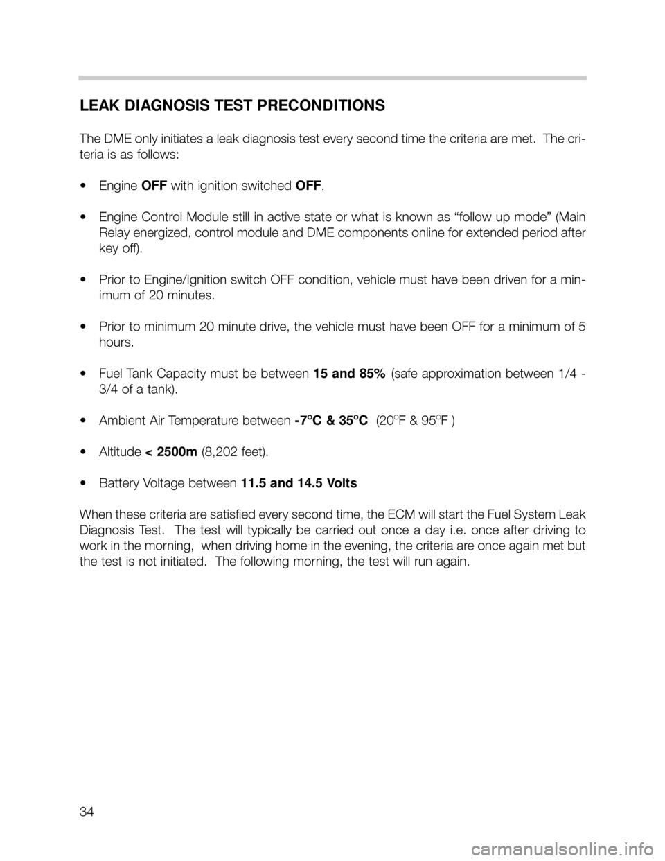
LEAK DIAGNOSIS TEST PRECONDITIONS
The DME only initiates a leak diagnosis test every second time the criteria are met. The cri-
teria is as follows:
• Engine OFF with ignition switched OFF.
• Engine Control Module still in active state or what is known as “follow up mode” (Main
Relay energized, control module and DME components online for extended period after
key off).
• Prior to Engine/Ignition switch OFF condition, vehicle must have been driven for a min-
imum of 20 minutes.
• Prior to minimum 20 minute drive, the vehicle must have been OFF for a minimum of 5
hours.
• Fuel Tank Capacity must be between 15 and 85%(safe approximation between 1/4 -
3/4 of a tank).
• Ambient Air Temperature between -7
OC & 35OC(20OF & 95OF )
• Altitude < 2500m(8,202 feet).
• Battery Voltage between 11.5 and 14.5 Volts
When these criteria are satisfied every second time, the ECM will start the Fuel System Leak
Diagnosis Test. The test will typically be carried out once a day i.e. once after driving to
work in the morning, when driving home in the evening, the criteria are once again met but
the test is not initiated. The following morning, the test will run again.
34