turn signal BMW X5 2001 E53 M62TU Engine Workshop Manual
[x] Cancel search | Manufacturer: BMW, Model Year: 2001, Model line: X5, Model: BMW X5 2001 E53Pages: 37, PDF Size: 3.87 MB
Page 5 of 37

5
BASIC FUNCTION OF BMW VANOS SYSTEMS
All BMW VANOS systems are operated through electric/hydraulic/mechanical control.
Electric Control: The engine control module is responsible for activating a VANOS sole-
noid valve based on DME program mapping. The activation parameters are influenced
by the following input signals:
• Engine speed
• Load (intake air mass)
• Engine temperature
• Camshaft position
• Oil temperature (MS 42.0 only)
Depending on the specific VANOS system, the solenoid valve is one of two types:
• Basic black/white (on/off) solenoid valve. Found on M50 TU and M52 engines.
• Variable position solenoid valve. Found on the M52 TU and M62 TU engines.
Hydraulic Control:The position of the solenoid valve directs the hydraulic flow of engine
oil. The controlled oil flow acts on the mechanical components of VANOS system to
position the camshaft.
Mechanical Control: The mechanical components of all VANOS systems operate under
the same principle. The controlled hydraulic engine oil flow is directed through advance
or retard activation oil ports. Each port exits into a sealed chamber on the opposite sides
of a control piston.
• The control piston on six cylinder engine systems (M50TU, M52 & M52TU) is con-
nected to a separate helical gear cup.
• The control piston on the M62TU VANOS system incorporates the helical gear.
In its default position the oil flow is directed to the rear surface of the piston. This pulls
the helical gear forward and maintains the retarded valve timing position.
When the oil flow is directed to the front surface of the piston, the oil pushesthe helical
gear in the opposite direction which rotates the matched helical gearing connected to the
camshaft.
The angled teeth of the helical gears cause thepushingmovement to be converted into
arotationalmovement. The rotational movement is added to the turning of the
camshaft providing the variable camshaft positioning.
Page 18 of 37

18
PWG SIGNAL MONITORING & PWG FAILSAFE OPERATION:
• As a redundant safety feature the PWG provides two separate signals from two integral
potentiometers (Pot 1 and Pot 2) representing the driver’s request for throttle activation.
• If the monitored PWG potentiometer signals are not plausible, ME 7.2 will only use the
lower of the two signals as the driver’s pedal request input providing failsafe operation.
Throttle response will be slower and maximum throttle position will be reduced.
• When in PWG failsafe operation, ME 7.2 sets the EDK throttle plate and injection time
to idle (LL) whenever the brake pedal is depressed.
• When the system is in PWG failsafe operation, the instrument cluster matrix display will
post “Engine Emergency Program” and PWG specific fault(s) will be stored in memory.
EDK FEEDBACK SIGNAL MONITORING & EDK FAILSAFE OPERATION:
• The EDK provides two separate signals from two integral potentiometers (Pot 1 and Pot
2) representing the exact position of the throttle plate.
• EDK Pot 1 provides the primary throttle plate position feedback. As a redundant safe-
ty feature, Pot 2 is continuously cross checked with Pot 1 for signal plausibility.
• If plausibility errors are detected between Pot 1 and Pot 2, ME 7.2 will calculate the
inducted engine air mass (from HFM signal) and only utilize the potentiometer signal that
closely matches the detected intake air mass.
- The ME 7.2 uses the air mass signalling as a “virtual potentiometer” (pot 3) for a
comparative source to provide failsafe operation.
- If ME 7.2 cannot calculate a plausible conclusion from the monitored pots (1 or 2
and virtual 3) the EDK motor is switched off and fuel injection cut out is activated
(no failsafe operation possible).
• The EDK is continuously monitored during all phases of engine operation. It is also
briefly activated when KL 15 is initially switched on as a “pre-flight check” to verify it’s
mechanical integrity (no binding, appropriate return spring tension, etc). This is accom-
plished by monitoring both the motor control amperage and the reaction speed of the
EDK feedback potentiometers. If faults are detected the EDK motor is switched off and
fuel injection cut off is activated (no failsafe operation possible). The engine does how-
ever continue to run extremely rough at idle speed.
• When a replacement EDK is installed, the ME 7.2 adapts to the new component
(required amperage draw for motor control, feedback pot tolerance differences, etc).
This occurs immediately after the next cycle of KL 15 for approximately 30 seconds.
During this period of adaptation, the maximum opening of the throttle plate is 25%.
Page 21 of 37

11
INTEGRATED AMBIENT BAROMETRIC PRESSURE SENSOR
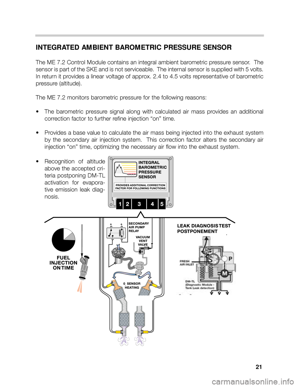
The ME 7.2 Control Module contains an integral ambient barometric pressure sensor. The
sensor is part of the SKE and is not serviceable. The internal sensor is supplied with 5 volts.
In return it provides a linear voltage of approx. 2.4 to 4.5 volts representative of barometric
pressure (altitude).
The ME 7.2 monitors barometric pressure for the following reasons:
• The barometric pressure signal along with calculated air mass provides an additional
correction factor to further refine injection “on” time.
• Provides a base value to calculate the air mass being injected into the exhaust system
by the secondary air injection system. This correction factor alters the secondary air
injection “on” time, optimizing the necessary air flow into the exhaust system.
• Recognition of altitude
above the accepted cri-
teria postponing DM-TL
activation for evapora-
tive emission leak diag-
nosis.
21
Page 24 of 37

24
EDK THROTTLE POSITION FEEDBACK SIGNALS
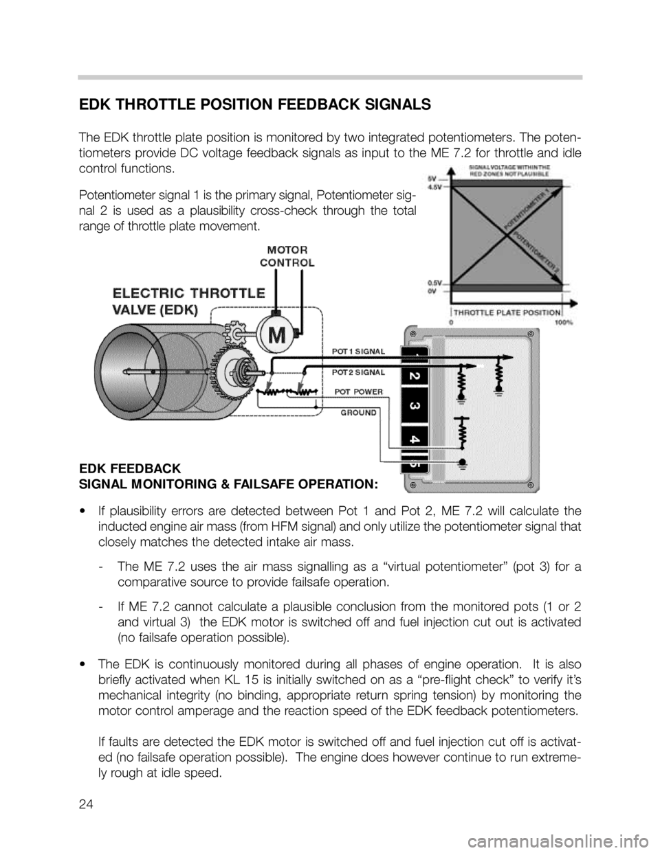
The EDK throttle plate position is monitored by two integrated potentiometers. The poten-
tiometers provide DC voltage feedback signals as input to the ME 7.2 for throttle and idle
control functions.
Potentiometer signal 1 is the primary signal, Potentiometer sig-
nal 2 is used as a plausibility cross-check through the total
range of throttle plate movement.
EDK FEEDBACK
SIGNAL MONITORING & FAILSAFE OPERATION:
• If plausibility errors are detected between Pot 1 and Pot 2, ME 7.2 will calculate the
inducted engine air mass (from HFM signal) and only utilize the potentiometer signal that
closely matches the detected intake air mass.
- The ME 7.2 uses the air mass signalling as a “virtual potentiometer” (pot 3) for a
comparative source to provide failsafe operation.
- If ME 7.2 cannot calculate a plausible conclusion from the monitored pots (1 or 2
and virtual 3) the EDK motor is switched off and fuel injection cut out is activated
(no failsafe operation possible).
• The EDK is continuously monitored during all phases of engine operation. It is also
briefly activated when KL 15 is initially switched on as a “pre-flight check” to verify it’s
mechanical integrity (no binding, appropriate return spring tension) by monitoring the
motor control amperage and the reaction speed of the EDK feedback potentiometers.
If faults are detected the EDK motor is switched off and fuel injection cut off is activat-
ed (no failsafe operation possible). The engine does however continue to run extreme-
ly rough at idle speed.