cruise control BMW X5 2001 E53 M62TU Engine Workshop Manual
[x] Cancel search | Manufacturer: BMW, Model Year: 2001, Model line: X5, Model: BMW X5 2001 E53Pages: 37, PDF Size: 3.9 MB
Page 15 of 37

15
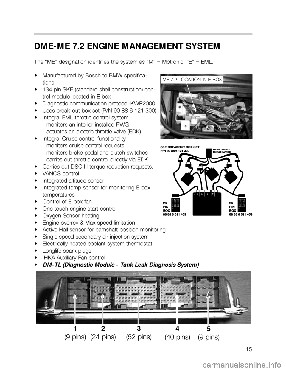
DME-ME 7.2 ENGINE MANAGEMENT SYSTEM
The “ME” designation identifies the system as “M” = Motronic, “E” = EML.
• Manufactured by Bosch to BMW specifica-
tions
• 134 pin SKE (standard shell construction) con-
trol module located in E box
• Diagnostic communication protocol-KWP2000
• Uses break-out box set (P/N 90 88 6 121 300)
• Integral EML throttle control system
- monitors an interior installed PWG
- actuates an electric throttle valve (EDK)
• Integral Cruise control functionality
- monitors cruise control requests
- monitors brake pedal and clutch switches
- carries out throttle control directly via EDK
• Carries out DSC III torque reduction requests.
• VANOS control
• Integrated altitude sensor
• Integrated temp sensor for monitoring E box
temperatures
• Control of E-box fan
• One touch engine start control
• Oxygen Sensor heating
• Engine overrev & Max speed limitation
• Active Hall sensor for camshaft position monitoring
• Single speed secondary air injection system
• Electrically heated coolant system thermostat
• Longlife spark plugs
• IHKA Auxiliary Fan control
•DM-TL (Diagnostic Module - Tank Leak Diagnosis System)
ME 7.2 LOCATION IN E-BOX
1
(9 pins)2
(24 pins)3
(52 pins)4
(40 pins)5
(9 pins)
Page 17 of 37

17
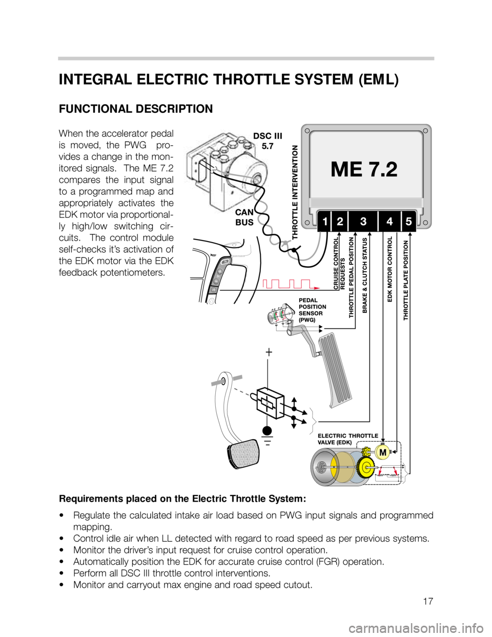
INTEGRAL ELECTRIC THROTTLE SYSTEM (EML)
FUNCTIONAL DESCRIPTION
When the accelerator pedal
is moved, the PWG pro-
vides a change in the mon-
itored signals. The ME 7.2
compares the input signal
to a programmed map and
appropriately activates the
EDK motor via proportional-
ly high/low switching cir-
cuits. The control module
self-checks it’s activation of
the EDK motor via the EDK
feedback potentiometers.
Requirements placed on the Electric Throttle System:
• Regulate the calculated intake air load based on PWG input signals and programmed
mapping.
• Control idle air when LL detected with regard to road speed as per previous systems.
• Monitor the driver’s input request for cruise control operation.
• Automatically position the EDK for accurate cruise control (FGR) operation.
• Perform all DSC III throttle control interventions.
• Monitor and carryout max engine and road speed cutout.
Page 22 of 37

22
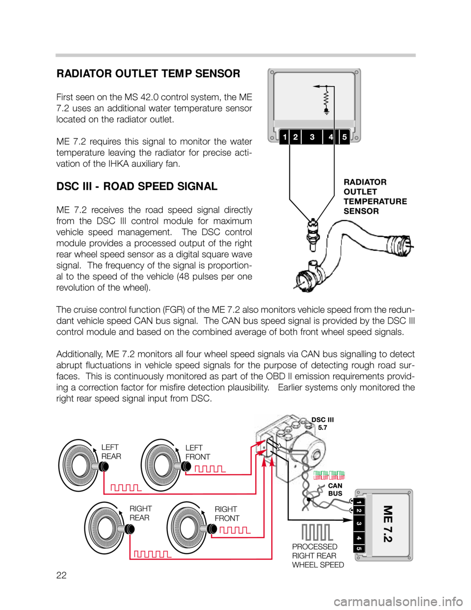
RADIATOR OUTLET TEMP SENSOR
First seen on the MS 42.0 control system, the ME
7.2 uses an additional water temperature sensor
located on the radiator outlet.
ME 7.2 requires this signal to monitor the water
temperature leaving the radiator for precise acti-
vation of the IHKA auxiliary fan.
DSC III - ROAD SPEED SIGNAL
ME 7.2 receives the road speed signal directly
from the DSC III control module for maximum
vehicle speed management. The DSC control
module provides a processed output of the right
rear wheel speed sensor as a digital square wave
signal. The frequency of the signal is proportion-
al to the speed of the vehicle (48 pulses per one
revolution of the wheel).
The cruise control function (FGR) of the ME 7.2 also monitors vehicle speed from the redun-
dant vehicle speed CAN bus signal. The CAN bus speed signal is provided by the DSC III
control module and based on the combined average of both front wheel speed signals.
Additionally, ME 7.2 monitors all four wheel speed signals via CAN bus signalling to detect
abrupt fluctuations in vehicle speed signals for the purpose of detecting rough road sur-
faces. This is continuously monitored as part of the OBD II emission requirements provid-
ing a correction factor for misfire detection plausibility. Earlier systems only monitored the
right rear speed signal input from DSC.
Page 25 of 37

25
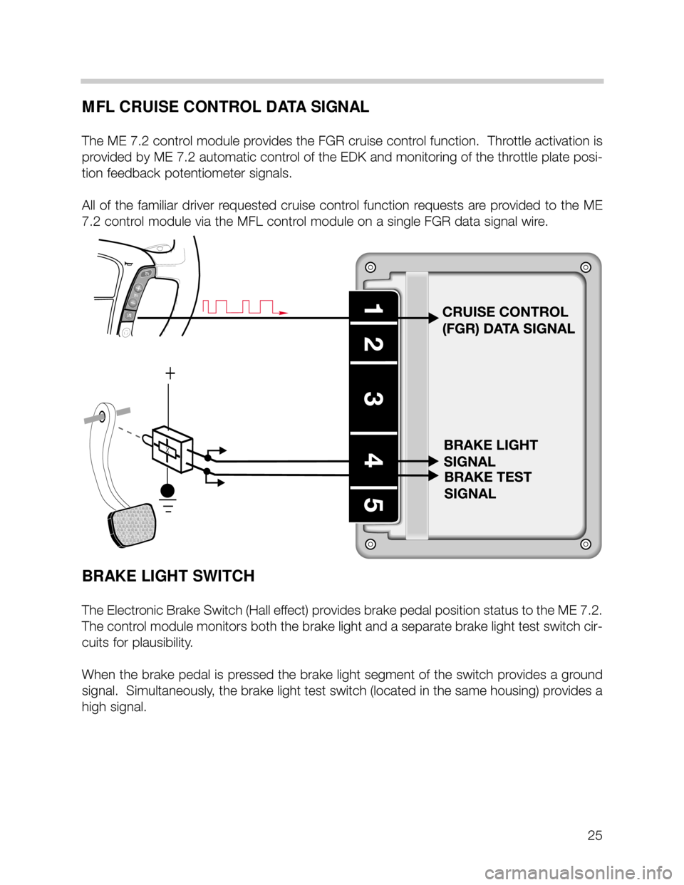
MFL CRUISE CONTROL DATA SIGNAL
The ME 7.2 control module provides the FGR cruise control function. Throttle activation is
provided by ME 7.2 automatic control of the EDK and monitoring of the throttle plate posi-
tion feedback potentiometer signals.
All of the familiar driver requested cruise control function requests are provided to the ME
7.2 control module via the MFL control module on a single FGR data signal wire.
BRAKE LIGHT SWITCH
The Electronic Brake Switch (Hall effect) provides brake pedal position status to the ME 7.2.
The control module monitors both the brake light and a separate brake light test switch cir-
cuits for plausibility.
When the brake pedal is pressed the brake light segment of the switch provides a ground
signal. Simultaneously, the brake light test switch (located in the same housing) provides a
high signal.