sensor BMW X5 2002 E53 DSC System Workshop Manual
[x] Cancel search | Manufacturer: BMW, Model Year: 2002, Model line: X5, Model: BMW X5 2002 E53Pages: 24, PDF Size: 1.77 MB
Page 1 of 24
TABLE OF CONTENTS
Subject Page
Dynamic Stability Control (DSC III) . . . . . . . . . . . . . . . . . . . . . . . . . . . . . . . . .2
Corner Braking Control . . . . . . . . . . . . . . . . . . . . . . . . . . . . . . . . . . . . . . . . .9
Electronic Brake Proportioning (EBV) . . . . . . . . . . . . . . . . . . . . . . . . . . . . . . .10
Dynamic Braking System . . . . . . . . . . . . . . . . . . . . . . . . . . . . . . . . . . . . . . .11
DSC New Functions . . . . . . . . . . . . . . . . . . . . . . . . . . . . . . . . . . . . . . . . . . .12
DSC New Feature . . . . . . . . . . . . . . . . . . . . . . . . . . . . . . . . . . . . . . . . . . . .15
Control Module Hydraulic Unit . . . . . . . . . . . . . . . . . . . . . . . . . . . . . . . . . . . .18
Rotation Rate/Transverse Acceleration Sensor . . . . . . . . . . . . . . . . . . . . . . . .19
Brake Pressure Sensor . . . . . . . . . . . . . . . . . . . . . . . . . . . . . . . . . . . . . . . . .20
DSC III Components . . . . . . . . . . . . . . . . . . . . . . . . . . . . . . . . . . . . . . . . . . .21
Steering Angle Sensor . . . . . . . . . . . . . . . . . . . . . . . . . . . . . . . . . . . . . . . . .22
Brake Fluid Level Warning Switch . . . . . . . . . . . . . . . . . . . . . . . . . . . . . . . . .23
Diagnosis . . . . . . . . . . . . . . . . . . . . . . . . . . . . . . . . . . . . . . . . . . . . . . . . . . .24
Page 3 of 24
3
TRACTION CONTROL SYSTEM OVERVIEW (ASC)
THEORY OF TRACTION CONTROL
Traction Control Systems are referred to as Automatic Stability Control (ASC), Automatic
Stability + Traction Control (ASC+T), Dynamic Stability Control (DSC) or All Season Traction
(marketing term). The traction control system has gone through several changes since its
introduction in Model Year 1988. While each new version offered new innovations, the prin-
ciple of traction control remains the same for any of these versions.
The link between the vehicle and its driving environment is established by the frictional con-
tact between the tires and the road surface. The ability to control the vehicle while driving,
is lost as a result of excessive wheel spin or slip if either rear tire exceeds its ability to:
• Maintain traction
• Accept side forces to maintain directional control (lateral locating forces)
The primary function of the traction control system is to maintain traction and stability of the
vehicle regardless of the road surface condition. This is achieved by reducing the drive
torque applied to the rear wheels or pulsing the rear wheel brakes to eliminate wheel slip
depending on the version of traction control installed.
The electronics for traction control operation are incorporated in the ABS control module
and share many of the same components and sensors. The module determines the speed
of the vehicle through a calculated average of the four wheel speed sensor inputs. Wheel
slip/spin is then recognized by comparing the speed of the driven wheels to the front
wheels.
A critical slip ratio of greater than 5% between the wheels will cause the traction control regu-
lation to begin. This slip ratio is established when the control module detects a wheel speed
difference of 2 MPH or higher.
Page 7 of 24
7
DYNAMIC STABILITY CONTROL (DSC III)
All of the familiar braking and straight line traction control features and system communi-
cation carry over from DSC II. Based on select high/select low logic, the DSC III control
module selects a vehicle stabilizing strategy based on the specific input signal values it is
monitoring at the moment. For all DSC strategies this begins with engine intervention to
reduce torque:
•For the 750iL this is handled via CAN communication, DSC III to EML to minimize the
throttle angle of the DK motors (750iL). For the 740i/iL and 540iA this is handled by
direct DSC III activation of the ADS II throttle housing.
• If additional torque reduction is necessary, DSC III informs DME over CAN to:
• Retard ignition timing
• Shut down the fuel injection to individual cylinders
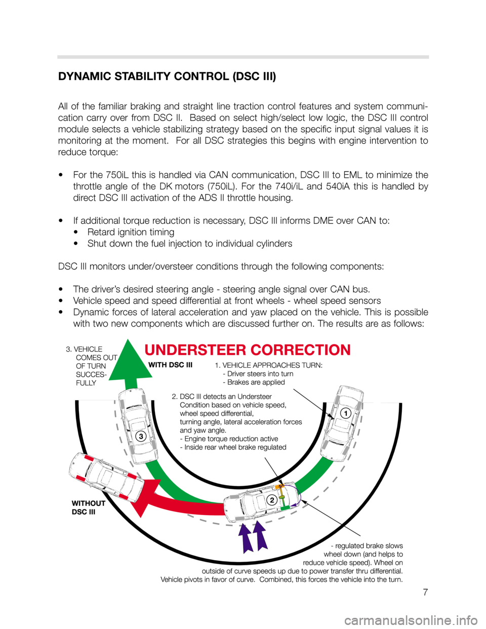
DSC III monitors under/oversteer conditions through the following components:
• The driver’s desired steering angle - steering angle signal over CAN bus.
• Vehicle speed and speed differential at front wheels - wheel speed sensors
• Dynamic forces of lateral acceleration and yaw placed on the vehicle. This is possible
with two new components which are discussed further on. The results are as follows:
Page 10 of 24
10
ELECTRONIC BRAKE PROPORTIONING (EBV)
Electronic brake proportioning allows the DSC system to adjust the braking force to the rear
wheels based on the vehicle’s loading to maximize the braking force at all wheels.
The DSC control module monitors the wheel speed sensors inputs when the brakes are
applied, for activation of this feature. The control module compares the speed at which the
front and rear axles are slowing down to determine vehicle loading.
If the rear axle is slowing at a similar rate to the front, it indicates that the vehicle is loaded
and more braking force can be applied to the rear calipers to slow and stop the vehicle.
If the decel rate of the rear axle is much less than the front, the vehicle is lightly loaded and
less force can be applied to the rear. If the same force were applied, then the vehicle could
become unstable.
OPERATION
The values for the decel rate are programmed in the DSC control module. Equal force will
be applied to the front and rear axles until the threshold values are exceeded. At this point,
the DSC control module will cycle the inlet valves at the rear calipers to reduce the braking
force on the rear axle.
Page 11 of 24
11
DYNAMIC BRAKING SYSTEM
The dynamic braking system is designed to enhance the braking control of the DSC for the
driver of the vehicle. The dynamic braking control and maximum braking control are func-
tions that are programmed into the control electronics of the DSC with no additional hard-
ware changes.
DYNAMIC BRAKING CONTROL (DBC)
The DBC function is designed to provide the maximum braking force available during rapid
(panic) braking situations. The DSC control module looks at the inputs from the brake pedal
switch and the signal from the brake pressure sensor on the master cylinder. The criteria
for activation of DBC is how rapidly is the brake pressure built up with the brake pedal
depressed. The total criteria required for DBC activation includes:
• Brake switch ON
• Brake pressure build up > threshold value
• Vehicle road speed > 5MPH
• Vehicle not in reverse
• Not all wheels in ABS regulation
If the threshold for DBC activation is achieved, the DSC control module will activate a pres-
sure build up regulation phase through the hydraulic unit. The pressure at all wheels is
increased up to the ABS regulation point. This occurs even if the driver does not achieve
the ABS regulation point with the pedal.
The rear axle brakes are controlled with select-low regulation and the front axle brakes are
controlled individually. ABS regulation will continue until the driver releases the pedal and
the pressure in the master cylinder drops below the threshold value stored in the DSC con-
trol module.
MAXIMUM BRAKE CONTROL (MBC)
The MBC function is also designed to enhance a driver initiated braking procedure. The
MBC will build up the pressure in the rear brake circuit when the front brakes are already in
an ABS regulation cycle. The additional braking pressure at the rear wheels will shorten the
stopping distance. The following criteria must be met before the DSC control module will
activate MBC:
• Both front wheel brakes in ABS regulation
• Vehicle speed > 5 MPH
• Vehicle not in reverse
• DBC and pressure sensor initialization test OK
• Rear wheels not in ABS regulation
Page 15 of 24
15
DSC - NEW FEATURE
TRACTION CONTROL
The traction control feature of the DSC III on the X5 cannot be switched OFF with the DSC
switch. Pressing the button will only switch off the dynamic stability control function of the
DSC.
The traction control feature is needed at all times to provide anti-spin control especially
when driving the vehicle off road. The DSC warning lamp in the instrument cluster will still
come on when the system is switched off manually or there is a fault in the system.
Off road traction control or HDC regulation places an additional load on the brakes. To pre-
vent overheating of the brakes and rotors, the temperature of the rotors is calculated over
time from the road speed and amount of brake application. If the temperature of one or
more rotors goes above 600o
C, the traction control or HDC function for that wheel will be
cancelled temporarily. Once the temperature of the rotor goes below 500o
C, the traction
application will be re-activated.
The normal braking function (including ABS) is always active at any temperatures.
DSC - NEW FEATURE
OFF-ROAD ABS Control Module Programming
The programming for ABS regulation have changed to allow a higher threshold for ABS reg-
ulation when driving off-road in loose gravel or dirt. A locked wheel is more effective in slow-
ing or stopping the vehicle because of the wedge that is built up in front of the tire.
The programming in the DSC control module allows one or both front wheel(s) to lock up
to a speed of 12 MPH as long as the vehicle is traveling straight ahead. If the DSC control
module receives a signal from the steering angle sensor indicating a turn, ABS regulation
will activate to prevent the lock and allow the vehicle to be steered.
Page 19 of 24
19
ROTATION RATE/TRANSVERSE ACCELERATION SENSOR
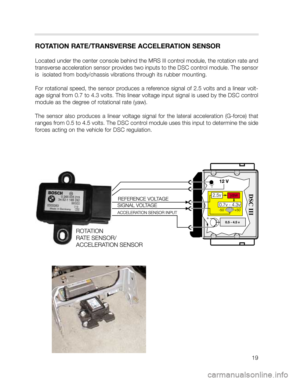
Located under the center console behind the MRS III control module, the rotation rate and
transverse acceleration sensor provides two inputs to the DSC control module. The sensor
is isolated from body/chassis vibrations through its rubber mounting.
For rotational speed, the sensor produces a reference signal of 2.5 volts and a linear volt-
age signal from 0.7 to 4.3 volts. This linear voltage input signal is used by the DSC control
module as the degree of rotational rate (yaw).
The sensor also produces a linear voltage signal for the lateral acceleration (G-force) that
ranges from 0.5 to 4.5 volts. The DSC control module uses this input to determine the side
forces acting on the vehicle for DSC regulation.
Page 20 of 24
20
BRAKE PRESSURE SENSOR
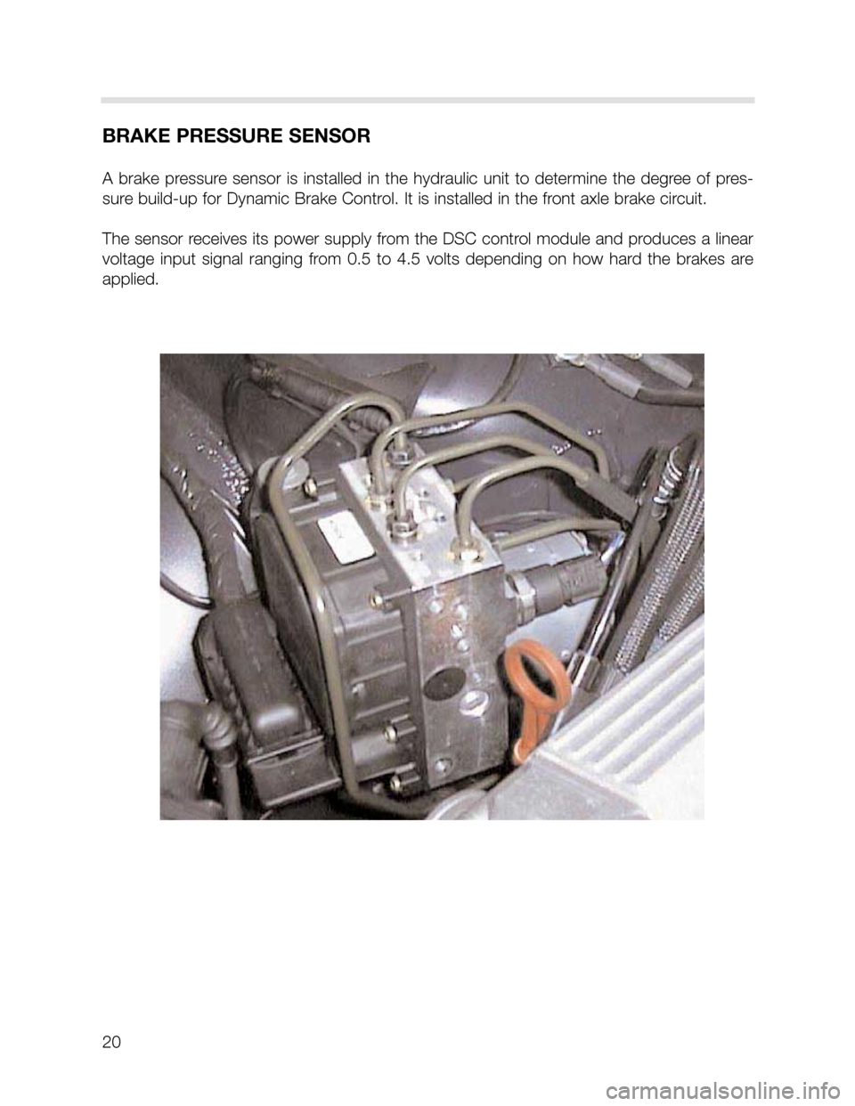
A brake pressure sensor is installed in the hydraulic unit to determine the degree of pres-
sure build-up for Dynamic Brake Control. It is installed in the front axle brake circuit.
The sensor receives its power supply from the DSC control module and produces a linear
voltage input signal ranging from 0.5 to 4.5 volts depending on how hard the brakes are
applied.
Page 21 of 24
21
DSC III COMPONENTS
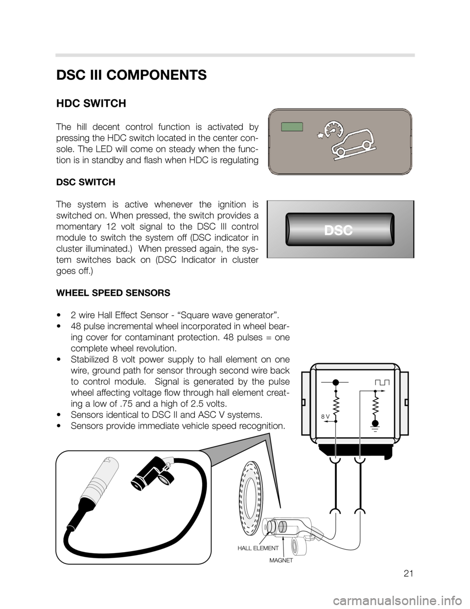
HDC SWITCH
The hill decent control function is activated by
pressing the HDC switch located in the center con-
sole. The LED will come on steady when the func-
tion is in standby and flash when HDC is regulating
DSC SWITCH
The system is active whenever the ignition is
switched on. When pressed, the switch provides a
momentary 12 volt signal to the DSC III control
module to switch the system off (DSC indicator in
cluster illuminated.) When pressed again, the sys-
tem switches back on (DSC Indicator in cluster
goes off.)
WHEEL SPEED SENSORS
• 2 wire Hall Effect Sensor - “Square wave generator”.
• 48 pulse incremental wheel incorporated in wheel bear-
ing cover for contaminant protection. 48 pulses = one
complete wheel revolution.
• Stabilized 8 volt power supply to hall element on one
wire, ground path for sensor through second wire back
to control module. Signal is generated by the pulse
wheel affecting voltage flow through hall element creat-
ing a low of .75 and a high of 2.5 volts.
• Sensors identical to DSC II and ASC V systems.
• Sensors provide immediate vehicle speed recognition.
Page 22 of 24
STEERING ANGLE SENSOR
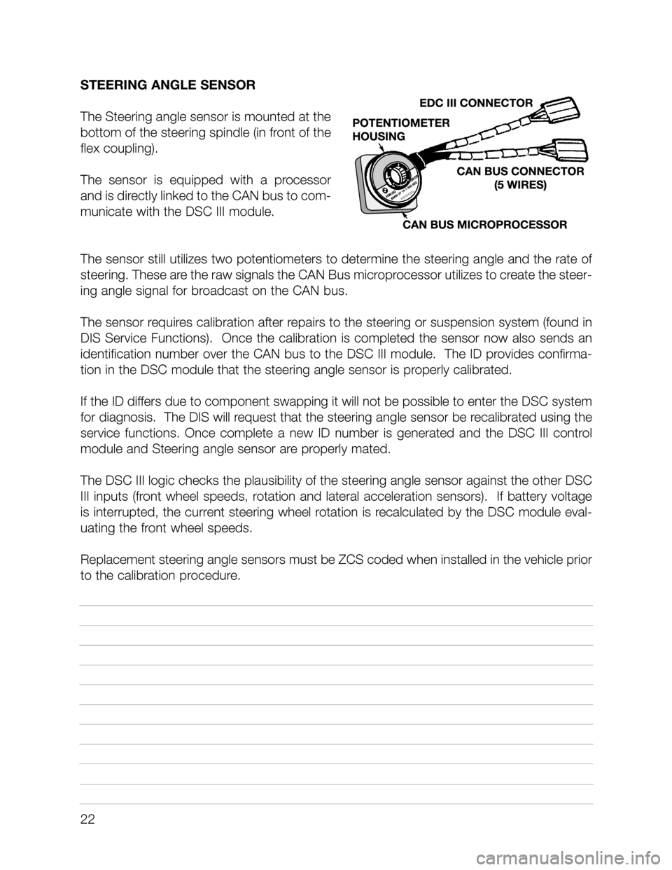
The Steering angle sensor is mounted at the
bottom of the steering spindle (in front of the
flex coupling).
The sensor is equipped with a processor
and is directly linked to the CAN bus to com-
municate with the DSC III module.
The sensor still utilizes two potentiometers to determine the steering angle and the rate of
steering. These are the raw signals the CAN Bus microprocessor utilizes to create the steer-
ing angle signal for broadcast on the CAN bus.
The sensor requires calibration after repairs to the steering or suspension system (found in
DIS Service Functions). Once the calibration is completed the sensor now also sends an
identification number over the CAN bus to the DSC III module. The ID provides confirma-
tion in the DSC module that the steering angle sensor is properly calibrated.
If the ID differs due to component swapping it will not be possible to enter the DSC system
for diagnosis. The DIS will request that the steering angle sensor be recalibrated using the
service functions. Once complete a new ID number is generated and the DSC III control
module and Steering angle sensor are properly mated.
The DSC III logic checks the plausibility of the steering angle sensor against the other DSC
III inputs (front wheel speeds, rotation and lateral acceleration sensors). If battery voltage
is interrupted, the current steering wheel rotation is recalculated by the DSC module eval-
uating the front wheel speeds.
Replacement steering angle sensors must be ZCS coded when installed in the vehicle prior
to the calibration procedure.
22