ECO BMW X5 2002 E53 Level Control System Manual
[x] Cancel search | Manufacturer: BMW, Model Year: 2002, Model line: X5, Model: BMW X5 2002 E53Pages: 57, PDF Size: 1.89 MB
Page 30 of 57
30
Level Control Systems
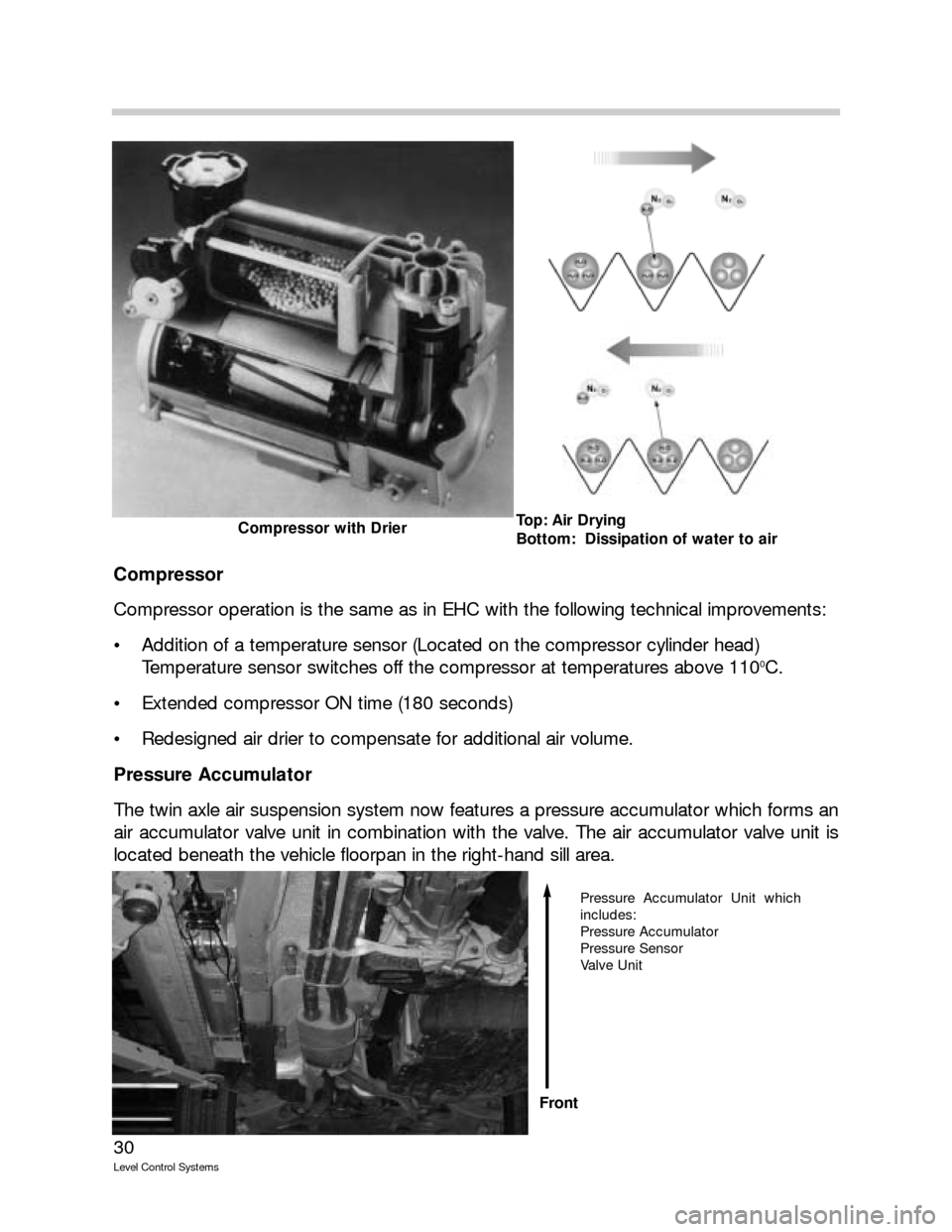
Compressor
Compressor operation is the same as in EHC with the following technical improvements:
Addition of a temperature sensor (Located on the compressor cylinder head)
Temperature sensor switches off the compressor at temperatures above 110
0C.
Extended compressor ON time (180 seconds)
Redesigned air drier to compensate for additional air volume.
Pressure Accumulator
The twin axle air suspension system now features a pressure accumulator which forms an
air accumulator valve unit in combination with the valve. The air accumulator valve unit is
located beneath the vehicle floorpan in the right-hand sill area.
Top: Air Drying
Bottom: Dissipation of water to airCompressor with Drier
Pressure Accumulator Unit which
includes:
Pressure Accumulator
Pressure Sensor
Valve Unit
Front
Page 36 of 57

36
Level Control Systems
The various levels can be preselected while travelling. Changeover between ride levels is
effected at the speed threshold values defined in the control unit. The control unit monitors
the change-over.
As soon as the driver sets a new target ride level by pressing a button or when a change-
over is initiated automatically by a specific driving condition, the LED for the current ride
level remains lit and the LED for the target ride level begins to flash.
When the new level is reached, the LED for the previous level goes out and the LED for the
new level reached stays lit permanently.
If a ride level selection is not allowed, the LED indicating the momentary ride level of the
vehicle flashes for 3 seconds.
A special case is preselection of Access levels while travelling. The Access LED flashes and
the LED for the original ride level is lit permanently. However, this does not mean that a con-
trol operation has already begun. The control operation does not actually begin until the
speed threshold which the Access level allows is reached or undershot.
Off-Road
(+25 mm)
Standard
(0 mm)
Access
(-35 mm)
Up button
and
<50km/h
Up button
or
>35km/h Up button
or
60 s time period
Access
Preselection
<25km/h Down Button and
<80km/h
and
Accumulator pressure
>threshold
and/or
compressor temperature
or
>50km/h
Page 39 of 57
39
Level Control Systems
Workshop Hints
If a threshold level is exceeded on all 4 wheels when the vehicle is stationary, the control
unit assumes that the vehicle has been raised on a workshop platform.
There are three possible reset conditions for workshop platform recognition:
The original level values are undershot at all four wheels,
A selection is made by button,
A speed of >40 km/h is recognized for 3 s.
Vehicle jack
If the lowering speed at a wheel is too low during the lowering operation, the system
assumes that the wheel is jacked up. However, the downward velocity must be less than
a certain preprogrammed speed threshold. If the system detects a jacked wheel, it stores
the height of this wheel.
Car jack recognition is reset when the stored ride height is again undershot. When a trav-
elling speed of 40 km/h is maintained for at least 3 s, another control attempt is performed.
The car jack recognition can also be reset by button selection.
Please note that the system also controls ride height in diagnostic mode. For this reason,
Belt Mode must be activated before carrying out work on the system or before setting the
vehicle ride height.
Belt Mode:
Heights are fixed and are not compensated. If Belt Mode is set, the function LED is off. The
text message "ride-height control system inactive" appears in the instrument cluster.
Transport Mode:
The Transport Mode setting is for transportation purposes. When the ignition is turned on,
the message "ride-height control system inactive" appears. Heights are increased or
decreased depending on ignition key status, e.g. ride height is reduced when the vehicle is
lashed to a ship or train and raised when the "Engine on" signal is generated and when the
vehicle is transported on a transporter truck.
The correct ride height is set to ± 5 mm via "Activate components." The left and right ride
levels are set separately at the rear axle. The ride levels are then set at the front axle. The
left and right air springs are adjusted jointly for this purpose.
Following this, the new ride height for the front and rear axles is stored via the "Offset func-
tion."
Before replacing components, the system must be depressurized! This is done in the diag-
nostics via "control unit functions," "Component activation," "Pressure-relieve front axle/rear
axle." Repeat the activation procedure 6 times.
Page 40 of 57
40
Level Control Systems
If the fabric of the bellows is visible, then the bellows must be replaced.
Upon completion of repair work, the air suspension system of the vehicle raised on the
workshop platform must be refilled with air via the diagnostics. The activation procedures
must also be repeated 6 times. This prevents the bellows from being folded incorrectly.
The vehicle must with be set down on its wheels when the suspension struts are depres-
surized!
Important Workshop Hint
S Si
im
mi
il
la
ar
rl
ly
y,
,
a
a
d
de
ef
fe
ec
ct
ti
iv
ve
e
v
ve
eh
hi
ic
cl
le
e
w
wi
it
th
h
l
le
ea
ak
ky
y
p
pn
ne
eu
um
ma
at
ti
ic
c
s
sy
ys
st
te
em
m
m
mu
us
st
t
n
no
ot
t
b
be
e
r
ra
ai
is
se
ed
d
o
on
n
t
th
he
e
w
wo
or
rk
k-
-
s sh
ho
op
p
p
pl
la
at
tf
fo
or
rm
m.
.
I
If
f
d
de
ep
pr
re
es
ss
su
ur
ri
iz
ze
ed
d,
,
t
th
he
e
b
be
el
ll
lo
ow
ws
s
w
wo
ou
ul
ld
d
c
co
on
nt
tr
ra
ac
ct
t
u
un
nd
de
er
r
s
su
uc
ct
ti
io
on
n
f
fo
or
rm
mi
in
ng
g
i
in
nc
co
or
rr
re
ec
ct
t
f fo
ol
ld
ds
s.
.
T
Th
he
es
se
e
f
fo
ol
ld
ds
s
c
co
ou
ul
ld
d
r
re
es
su
ul
lt
t
i
in
n
m
ma
al
lf
fu
un
nc
ct
ti
io
on
ns
s
l
la
at
te
er
r
o
on
n.
.
Areas on the air bellows which can possibly become leaky are the O-ring at the piston rod
and the seal carrier on the roll piston.
The connectors attached to all cables are identical to the connections on the single-axle air
suspension. 6 mm cable is used. The tightening torque is 3+
1 Nm throughout the system.
Special care must be taken when handling breakage-prone plastic parts of air suspension
elements.
Upon completion of repair work, Belt mode must be deactivated via the diagnostics. The
function LED on the button comes on. No text message appears in the instrument cluster.
The system is OK and ready for operation.
Page 50 of 57
50
Level Control Systems
Normal
The normal mode is the starting point for the vehicle’s normal operating state. It is obtained
by way of the engine running signal.
Ride level compensation, changing the vehicle’s ride height and filling the accumulator are
possible. The compressor starts up as required.
A narrower tolerance band than that in Pre-mode cab be used because the battery capac-
ity does not have to be protected. The fast filter is used with a narrow tolerance band of
+/- 10mm. In this way, ride level compensation takes place outside a narrow band of 10+/-
10mm. The faster filter allows the system to respond immediately to changes in ride level.
Evaluation and control are performed separately for each wheel.
When a speed signal is recognized, the control unit switches into Drive mode. When the
vehicle is stopped, the control unit remains in Drive mode. The system switches back into
Normal mode when a door or the boot (trunk) lid is also opened. If none of the doors or
the boot lid is opened, the vehicle cannot be loaded or unloaded.
This prevents a control operation happening when the vehicle (for example) is stopped at
traffic lights and the ride height is above the mean axle due to the pitching motion on the
rear axle.
Drive
The Drive mode is activated for E39/E53 single axle air suspension when a speed signal of
>4km/h is recognized. The Drive mode is recognized from >1km/h for the E65/E66 single
axle air suspension and for the E53 twin-axle air suspension system.
Low pass filters are used. In this way, only changes in ride height over a prolonged period
of time (1000 seconds) are corrected. These are merely the changes in ride height, caused
by vehicle compression and a reduction in vehicle mass due to fuel consumption. The high
pass (fast) filter is used during the control operation. The slow filters are recognized at the
end of the control operation. The slow filters are re-initialized at the end of the control oper-
ation. The markedly dynamic height signals caused by uneven road surfaces are filtered
out.
Page 51 of 57
51
Level Control Systems
Kerb (Curb) Mode
The Kerb mode prevents the inclination caused by the vehicle mounting an obstacle with
ine wheel from being compensated. Compensation would cause a renewed inclination of
the vehicle and result in a renewed control operation after the vehicle comes off the obsta-
cle.
The Kerb Mode is activated when the height difference between the left and right sides of
the vehicle is > 32mm for the E65/E66 with single axle air suspension and >24mm for the
E39/E53 with single axle air suspension and lasts longer than 0.9s. Twisting (also over both
axles) > 45mm must occur for the E53 with twin axle air suspension.
There must be no speed signal present. The system switches from single wheel control to
axle control.
The Kerb mode is quit when the difference between the left and right sides of the vehicle is
< 28mm for the single axle air suspension and lasts longer than 0.9s when the speed is
greater than > 1km/h.
If the system switches from Kerb mode to Sleep mode, this status is stored in the
EEPROM.
If the vehicle is loaded or unloaded in Kerb mode, the mean value of the axle is calculated
by the control unit. The value is calculated in the control unit from the changes in ride level
of the spring travel on the left and right sides.
A change in ride level is initiated if the mean value of compression or rebound at the axle is
outside the tolerance band of +/- 10mm. The left and right sides of the vehicle are raised
or lowered in parallel. The height difference between the two sides is maintained.
Curve
Since rolling motions have a direct impact on the measured ride level, an unwanted control
operation would be initiated during longer instances of cornering with an appropriate roll
angle in spite of the slow filtering of the Drive mode. The control operations during corner-
ing would cause displacement of the air volume from the outer side to the inner side of the
curve. Once the curve is completed, this would produce an inclination which would result
in a further control operation. The Curve mode prevents this control operation whereby
when cornering is recognized slow filtering is stopped and a potential control operation that
has started is terminated.
The Curve mode is activated for the E65/E66 single axle EHC and for the E53 twin axle
suspension for a lateral acceleration of > 2m/s
2and deactivated at < 1.5 m/s2.
The lateral acceleration is recorded by the rotation rate sensor.
Page 52 of 57
52
Level Control Systems
Lift
The Lift mode is used to prevent control operations when a wheel is changed or during
work on the vehicle while it is on a lifting platform.
This mode is recognized when the permitted rebound travel at one or more wheels is
exceeded. For the E65/E66 the limit is > 55mm.
A “jack” situation is also recognized when the ride level is stored and the lowering speed
drops below the value of 2 mm/s for 3 seconds.
If the vehicle has been raised slightly and the permitted rebound travel has not yet been
achieved, the control operation attempts to readjust the ride height. If the vehicle is not low-
ered, a car jack situation is recognized after a specific period of time and this ride height is
stored.
A reset is performed if the vehicle is again 10 mm below this stored ride height.
Transport
The Transport mode is set and cleared by means of a diagnosis activation. It serves to
increase the ground clearance in order to ensure a safe transportation of vehicles on trans-
porter trucks. The nominal height of the vehicle is raised in this mode by 30 mm.
When the Transport mode is activated, the air suspension symbol is indicated in the vari-
able telltale in the instrument cluster and a text message is output in the Check Control
Display.
Control operations do not take place in this mode because the vehicle mass does not
change during transportation.
Belt
The Belt mode is set for mounting on the belt in order to avoid control operations.
When the Belt mode is activated, the air suspension symbol is indicated in the variable tell-
tale in the instrument cluster and a text message is output in the Check Control display.
The Belt mode is cleared by means of a diagnostic activation only. The Belt mode can no
longer be set.
New control units are supplied with the Belt mode set.
Control operations are not performed, the safety concept only operates with limited effect.
The Belt Mode is also known as “Band Mode” or “Assembly Line Mode”.
Page 54 of 57

54
Level Control Systems
Safety Concept
The safety concept is intended to inhibit any system malfunction, particularly unintentional
control operations, through monitoring of signals and function relevant parameters. If faults
are detected, the system is switched over or shut down depending on the affected com-
ponent. The driver is informed of existing faults via the display. Detected faults are stored
for diagnostic purposes.
In order to ensure high system availability, existing faults, as far as possible, are cleared with
terminal 15 ON. This is done by resetting the fault counter to zero. However, the fault
memory content in the EEPROM is retained and can be read out for diagnostic purposes.
The system is then operational again. The fast troubleshooting helps to detect existing
faults before control operation can take place.
Only lowering is permitted if:
The permissible supply voltage of 9 volts is undershot
The permissible compressor running time of 480 seconds is exceeded.
A reset takes place if the voltage is in the OK range of 9 to 16 volts or after the compres-
sor pause time of 100 seconds has elapsed.
Only raising is permitted if:
The permissible control down period of 40 seconds is exceeded
The reset takes place the next time the vehicle is driven or after the next control up
operation.
No control operation takes place if:
The permissible supply voltage of 16 volts is exceeded
The reset takes place as soon as the voltage is in the OK range.