lock BMW X5 2002 E53 Level Control System Manual
[x] Cancel search | Manufacturer: BMW, Model Year: 2002, Model line: X5, Model: BMW X5 2002 E53Pages: 57, PDF Size: 1.89 MB
Page 5 of 57
5
Level Control Systems
System Components
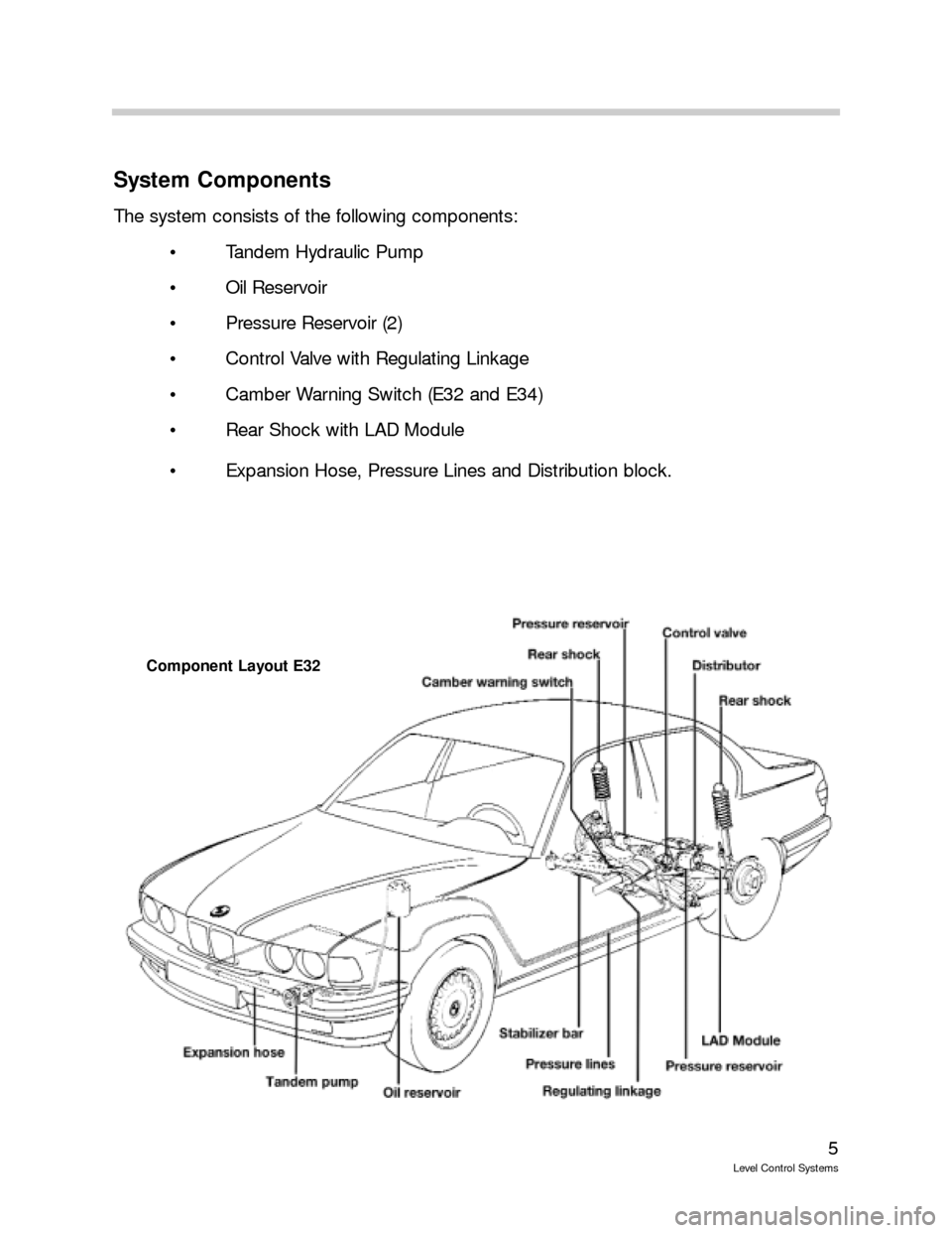
The system consists of the following components:
Tandem Hydraulic Pump
Oil Reservoir
Pressure Reservoir (2)
Control Valve with Regulating Linkage
Camber Warning Switch (E32 and E34)
Rear Shock with LAD Module
Expansion Hose, Pressure Lines and Distribution block.
Component Layout E32
Page 13 of 57
13
Level Control Systems
Air Suspension Systems (EHC)
Purpose of the System
Air Suspension systems were first introduced on the 1999 E39 Sportwagon. Since then
the E53 (X5) and E65/E66 (7Series) models were available with this new system. EHC are
available is two configurations, the Single Axle Air Suspension System and the Dual Axle
Air Suspension System. The Dual Axle (EHC II) system is only available on E53 X5 models
from the 2002 model year.
EHC systems can be found on the following vehicles:
E39 Sportwagon 528i, 525i and 540i from the 1999 Model Year (Single Axle)
E53 X5 3.0i and 4.4i from the 2000 Model Year (Single Axle)
E53 X5 4.6iS from 2002 (Single Axle)
E53 X5 3.0i and 4.4i from 2002 (Dual Axle EHC II)
E65/E66 from 2003 Model Year (Single Axle)
There are some functional changes with these systems. On EHC, the entire axle load is
borne by the air suspension. The underlying control philosophy of EHC is “Control only
when absolutely necessary”. This means that brief changes in the ride height are not com-
pensated (such as potholes). This avoids any unnecessary control operations.
The advantages of air suspension are as follows:
Control is independent of the vehicle engine
Single-wheel control is possible
Lateral locking is affected
A distinction is made between load and drive states
An inclined load is identified and corrected
However, an inclination is not compensated
Self diagnosis can be performed
Diagnosis with DISplus or GT-1 is possible
An automatic interruption of control takes place in case of cornering and wheel
changes.
Page 18 of 57
18
Level Control Systems
Air Supply System (LVA)
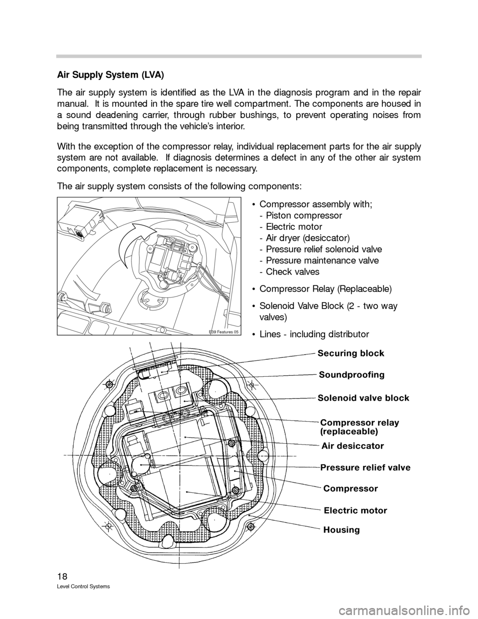
The air supply system is identified as the LVA in the diagnosis program and in the repair
manual. It is mounted in the spare tire well compartment. The components are housed in
a sound deadening carrier, through rubber bushings, to prevent operating noises from
being transmitted through the vehicle’s interior.
With the exception of the compressor relay, individual replacement parts for the air supply
system are not available. If diagnosis determines a defect in any of the other air system
components, complete replacement is necessary.
The air supply system consists of the following components:
Compressor assembly with;
- Piston compressor
- Electric motor
- Air dryer (desiccator)
- Pressure relief solenoid valve
- Pressure maintenance valve
- Check valves
Compressor Relay (Replaceable)
Solenoid Valve Block (2 - two way
valves)
Lines - including distributor
E39 Features 05
Page 19 of 57
19
Level Control Systems
Air Supply System (LVA) Operation
The single stage piston compressor produces a maximum pressure of 13.5 Bar. The com-
pressor is maintenance free - provided it is used in a dust free environment. This includes
the compressor’s intake air filter.
The compressor is driven by a DC motor that is controlled by the compressor relay through
the control module.
When the compressor is activated, the pressure builds up to a working pressure of 11.4
Bar (+0.8/-1.5 Bar). This is controlled through the pressure maintenance valve. The air
under pressure is fed through the dryer and check valve to the solenoid valve block for the
air springs.
There is one solenoid valve in the valve block for each air strut. This allows the system to
compensate for uneven loads in the vehicle and maintain the vehicles ride height at all
times.
Pressure is drained through the left or right solenoid valve (energized open) the pressure
relief solenoid valve, restrictor, check valve and dryer back to the inlet side of the compres-
sor pump.
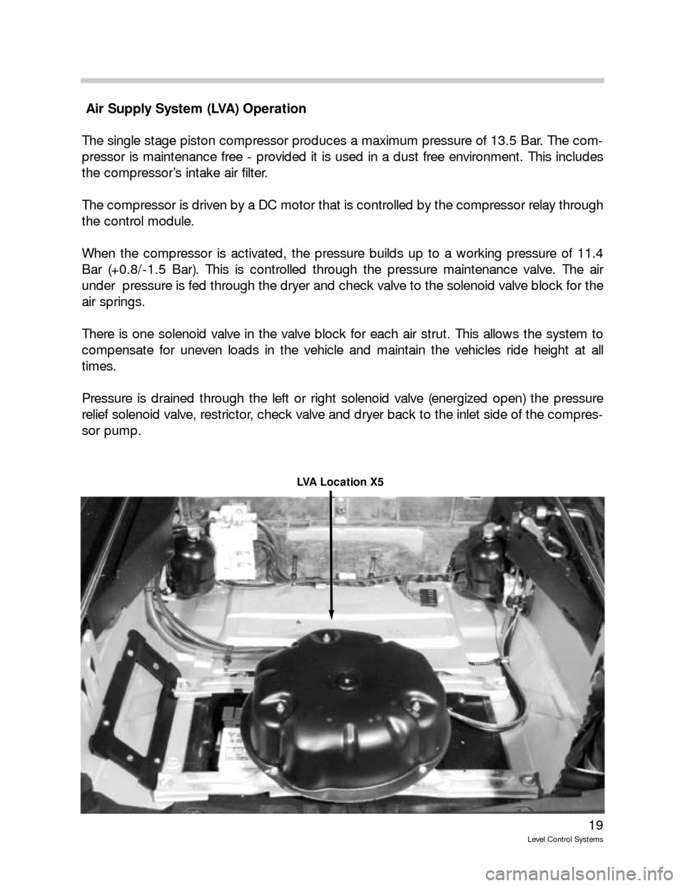
LVA Location X5
Page 43 of 57
43
Level Control Systems
Components (E65/E66)
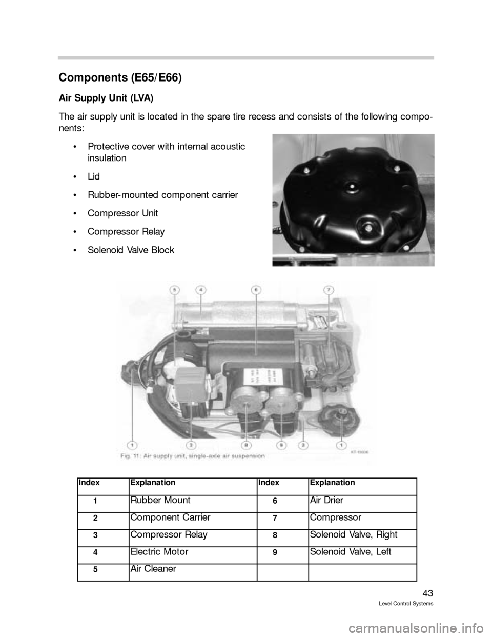
Air Supply Unit (LVA)
The air supply unit is located in the spare tire recess and consists of the following compo-
nents:
Protective cover with internal acoustic
insulation
Lid
Rubber-mounted component carrier
Compressor Unit
Compressor Relay
Solenoid Valve Block
IndexExplanationIndexExplanation
1Rubber Mount6Air Drier
2Component Carrier7Compressor
3Compressor Relay8Solenoid Valve, Right
4Electric Motor9Solenoid Valve, Left
5Air Cleaner
Page 45 of 57
45
Level Control Systems
Air Springs
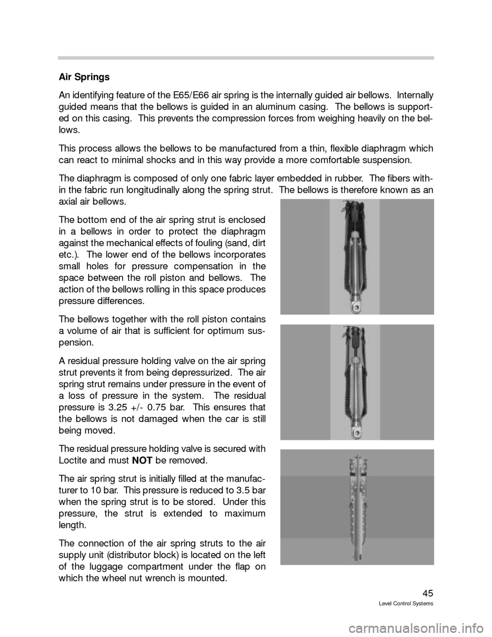
An identifying feature of the E65/E66 air spring is the internally guided air bellows. Internally
guided means that the bellows is guided in an aluminum casing. The bellows is support-
ed on this casing. This prevents the compression forces from weighing heavily on the bel-
lows.
This process allows the bellows to be manufactured from a thin, flexible diaphragm which
can react to minimal shocks and in this way provide a more comfortable suspension.
The diaphragm is composed of only one fabric layer embedded in rubber. The fibers with-
in the fabric run longitudinally along the spring strut. The bellows is therefore known as an
axial air bellows.
The bottom end of the air spring strut is enclosed
in a bellows in order to protect the diaphragm
against the mechanical effects of fouling (sand, dirt
etc.). The lower end of the bellows incorporates
small holes for pressure compensation in the
space between the roll piston and bellows. The
action of the bellows rolling in this space produces
pressure differences.
The bellows together with the roll piston contains
a volume of air that is sufficient for optimum sus-
pension.
A residual pressure holding valve on the air spring
strut prevents it from being depressurized. The air
spring strut remains under pressure in the event of
a loss of pressure in the system. The residual
pressure is 3.25 +/- 0.75 bar. This ensures that
the bellows is not damaged when the car is still
being moved.
The residual pressure holding valve is secured with
Loctite and must NOTbe removed.
The air spring strut is initially filled at the manufac-
turer to 10 bar. This pressure is reduced to 3.5 bar
when the spring strut is to be stored. Under this
pressure, the strut is extended to maximum
length.
The connection of the air spring struts to the air
supply unit (distributor block) is located on the left
of the luggage compartment under the flap on
which the wheel nut wrench is mounted.
Page 49 of 57
49
Level Control Systems
Post Mode
The Post-mode is adopted in order to compensate any inclination or to adjust the ride
height after driving and between the Pre-mode and Sleep mode.
The Post-mode is limited in time to 1 minute. The Post-mode is only executed if the engine
has been running before the system switches into this mode. If the engine has not been
previously running, the system switches directly from Pre-mode into Sleep mode.
The control operation is performed in a narrow tolerance band of +/- 6mm and is terminat-
ed at +/- 4mm. The fast signal filter is used.
In the event of an inclination (Kerb Mode), the control operation takes place for the nominal
heights applicable in this situation.
Pre-Mode
The Pre-mode is activated by the “Load Cutoff” signal (e.g. by opening the door or unlock-
ing with the remote control). The Pre-mode then stays set for 16 minutes and is restarted
with a change in status.
The ride height of the vehicle is monitored and evaluated with a wide tolerance band.
In Pre-mode, the vehicle is only controlled un to the nominal height if the level is significantly
below the nominal height. The control tolerance band is -40mm from the mean value for
the single axle air suspension and -20mm for the dual axle system. This control tolerance
ensures that the vehicle is only controlled up in the case of large loads in order to increase
the ground clearance prior to departure. Small loads give rise to small compression travel
and this is compensated only when the engine is started. This control setting helps reduce
the battery load.
With the single axle air suspension, the vehicle is controlled down when the mean value
derived from both ride height signals is > 0mm and one side is in excess of +10mm. With
twin axle air suspension, the vehicle is controlled down when one side is >15mm.
In this mode, only the mean value of the two height signals is considered when deciding
whether there is an need for control operation.
The control operation is executed as long as pressure is available in the accumulator. When
the accumulator is empty and the engine is turned off, the control operation is driven direct-
ly by the compressor. User-activated changes of ride level and filling of the accumulator are
not possible.
Control operations which were started in other modes are continued with the inner toler-
ance bands applicable to these modes.
There is no inclination identification in Pre-mode.