engine BMW X5 2002 E53 M54 Engine Owner's Guide
[x] Cancel search | Manufacturer: BMW, Model Year: 2002, Model line: X5, Model: BMW X5 2002 E53Pages: 48, PDF Size: 2.52 MB
Page 42 of 48

42
M54engMS43/ST036/6/2000
RESONANCE SYSTEM
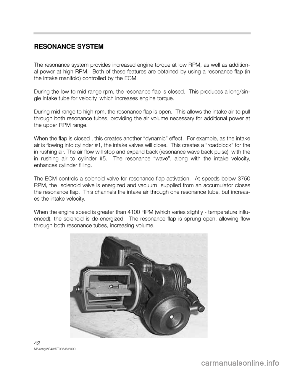
The resonance system provides increased engine torque at low RPM, as well as addition-
al power at high RPM. Both of these features are obtained by using a resonance flap (in
the intake manifold) controlled by the ECM.
During the low to mid range rpm, the resonance flap is closed. This produces a long/sin-
gle intake tube for velocity, which increases engine torque.
During mid range to high rpm, the resonance flap is open. This allows the intake air to pull
through both resonance tubes, providing the air volume necessary for additional power at
the upper RPM range.
When the flap is closed , this creates another “dynamic” effect. For example, as the intake
air is flowing into cylinder #1, the intake valves will close. This creates a “roadblock” for the
in rushing air. The air flow will stop and expand back (resonance wave back pulse) with the
in rushing air to cylinder #5. The resonance “wave”, along with the intake velocity,
enhances cylinder filling.
The ECM controls a solenoid valve for resonance flap activation. At speeds below 3750
RPM, the solenoid valve is energized and vacuum supplied from an accumulator closes
the resonance flap. This channels the intake air through one resonance tube, but increas-
es the intake velocity.
When the engine speed is greater than 4100 RPM (which varies slightly - temperature influ-
enced), the solenoid is de-energized. The resonance flap is sprung open, allowing flow
through both resonance tubes, increasing volume.
Page 45 of 48

45
M54engMS43/ST036/6/20000
IDLE SPEED CONTROL
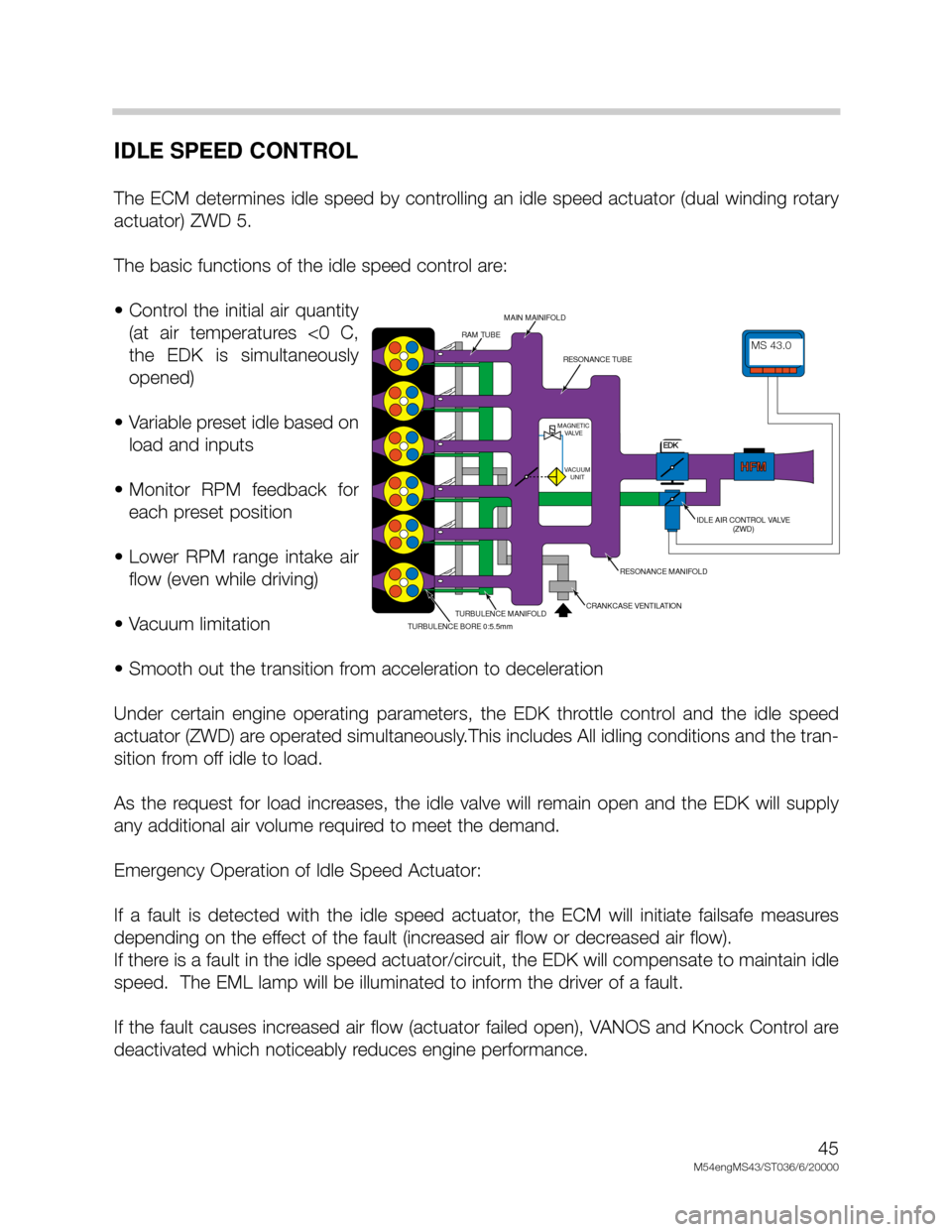
The ECM determines idle speed by controlling an idle speed actuator (dual winding rotary
actuator) ZWD 5.
The basic functions of the idle speed control are:
• Control the initial air quantity
(at air temperatures <0 C,
the EDK is simultaneously
opened)
• Variable preset idle based on
load and inputs
• Monitor RPM feedback for
each preset position
• Lower RPM range intake air
flow (even while driving)
• Vacuum limitation
• Smooth out the transition from acceleration to deceleration
Under certain engine operating parameters, the EDK throttle control and the idle speed
actuator (ZWD) are operated simultaneously.This includes All idling conditions and the tran-
sition from off idle to load.
As the request for load increases, the idle valve will remain open and the EDK will supply
any additional air volume required to meet the demand.
Emergency Operation of Idle Speed Actuator:
If a fault is detected with the idle speed actuator, the ECM will initiate failsafe measures
depending on the effect of the fault (increased air flow or decreased air flow).
If there is a fault in the idle speed actuator/circuit, the EDK will compensate to maintain idle
speed. The EML lamp will be illuminated to inform the driver of a fault.
If the fault causes increased air flow (actuator failed open), VANOS and Knock Control are
deactivated which noticeably reduces engine performance.
MDK
HFMHFM
MAGNETIC
VALVE
VACUUM
UNIT
MS42.0MS42.0
RAM TUBE
MAIN MAINIFOLD
RESONANCE TUBE
IDLE AIR CONTROL VALVE
(ZWD)
RESONANCE MANIFOLD
CRANKCASE VENTILATIONTURBULENCE MANIFOLD
TURBULENCE BORE 0:5.5mm
MS 43.0
EDK
Page 46 of 48

46
M54engMS43/ST036/6/2000
CRUISE CONTROL
Cruise control is integrated into the ECM because of the EDK operation.
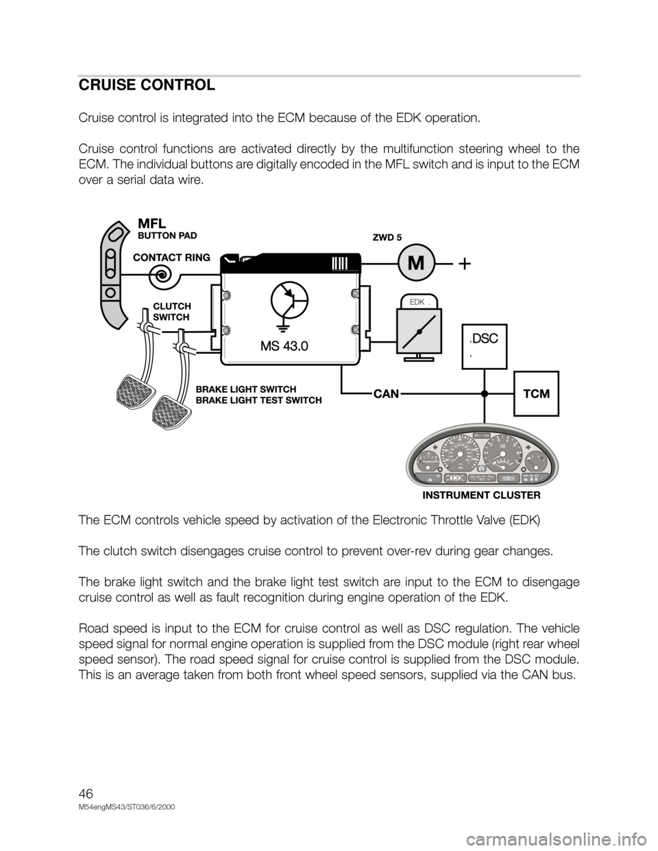
Cruise control functions are activated directly by the multifunction steering wheel to the
ECM. The individual buttons are digitally encoded in the MFL switch and is input to the ECM
over a serial data wire.
The ECM controls vehicle speed by activation of the Electronic Throttle Valve (EDK)
The clutch switch disengages cruise control to prevent over-rev during gear changes.
The brake light switch and the brake light test switch are input to the ECM to disengage
cruise control as well as fault recognition during engine operation of the EDK.
Road speed is input to the ECM for cruise control as well as DSC regulation. The vehicle
speed signal for normal engine operation is supplied from the DSC module (right rear wheel
speed sensor). The road speed signal for cruise control is supplied from the DSC module.
This is an average taken from both front wheel speed sensors, supplied via the CAN bus.
DSCMS 43.0
EDK