BMW X5 2003 E53 Central Body Electronics User Guide
Manufacturer: BMW, Model Year: 2003, Model line: X5, Model: BMW X5 2003 E53Pages: 64, PDF Size: 4.03 MB
Page 11 of 64
THEORY OF OPERATION:
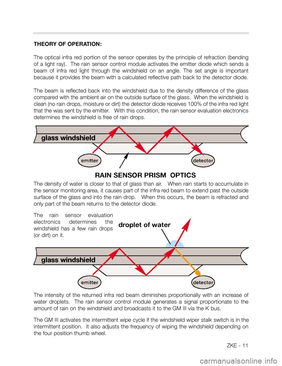
The optical infra red portion of the sensor operates by the principle of refraction (bending
of a light ray). The rain sensor control module activates the emitter diode which sends a
beam of infra red light through the windshield on an angle. The set angle is important
because it provides the beam with a calculated reflective path back to the detector diode.
The beam is reflected back into the windshield due to the density difference of the glass
compared with the ambient air on the outside surface of the glass. When the windshield is
clean (no rain drops, moisture or dirt) the detector diode receives 100% of the infra red light
that the was sent by the emitter. With this condition, the rain sensor evaluation electronics
determines the windshield is free of rain drops.
The density of water is closer to that of glass than air. When rain starts to accumulate in
the sensor monitoring area, it causes part of the infra red beam to extend past the outside
surface of the glass and into the rain drop. When this occurs, the beam is refracted and
only part of the beam returns to the detector diode.
The rain sensor evaluation
electronics determines the
windshield has a few rain drops
(or dirt) on it.
The intensity of the returned infra red beam diminishes proportionally with an increase of
water droplets. The rain sensor control module generates a signal proportionate to the
amount of rain on the windshield and broadcasts it to the GM III via the K bus.
The GM III activates the intermittent wipe cycle if the windshield wiper stalk switch is in the
intermittent position. It also adjusts the frequency of wiping the windshield depending on
the four position thumb wheel.
ZKE - 11
Page 12 of 64
ZKE - 12
RAIN SENSOR FUNCTION:
The rain sensor is online as soon as it receives KL R operating power.
• When the windshield wiper stalk switch is placed in the intermittent position the GM
signals the rain sensor control module via the K Bus of the request for intermittent
wiping and the position of the knurled wheel (sensitivity).
• As an acknowledgement, the rain sensor sends a command via the K Bus to activate
the wiper motor. If more than 12 seconds pass before the GM receives the
acknowledgement, the GM concludes the rain sensor has a defect and operates the
intermittent wipe function as a system not equipped with a rain sensor. The wiper
intermittent cycling is based solely on the knurled wheel setting.
• The rain sensor continuously monitors the windshield for rain accumulation and signals
the GM to activate the wipers based on the knurled wheel position and how fast the rain
accumulates on the windshield.
• The knurled wheel position signal (1-4) via the K bus informs the rain sensor of the
selected level of sensitivity.
- Position 1 (least sensitive) delays the wiper activation signal.
- Position 4 (most sensitive) sends the wiper activation signal to the GM sooner.
• When the wiper motor park contacts signal the GM of the wiper arm position, the signal
is simultaneously sent to the rain sensor as an indication that the windshield has been
cleared of water drops and causes the rain sensor to reset the sensitivity delay timer
back to 0.
• If night time driving is detected via the integral photocell, the sensitivity to water droplets
is increased causing a shorter delay than day time driving.
• Depending on the intensity of the rain the wipers will be operated continuously as if set
in the normal wiper stalk switch position regardless of the knurled wheel setting. For
this reason, the vehicle speed signal on the K bus is not utilized on rain sensor equipped
wiper systems.
• If the ignition switch is turned off with the wiper switch in the intermittent position, the
rain sensor will only become active after the ignition is switched back on and one of the
following occurs:
- The stalk switch is moved from the intermittent position and then back.
- The knurled wheel setting is adjusted.
- or the wash function is activated.
The reasoning behind this switching strategy is to have the driver make a conscious
decision to activate the system themselves.
Page 13 of 64
ZKE-13
RAIN SENSOR CONTROL MODULE ADAPTATION
The rain sensor control module adapts to the optics system environment as follows:
Windshield Aging:As the vehicle ages the possibility of stone chipping in the rain sensors
monitoring area may occur which will cause a loss of light in the optics system.
The control module adapts for loss of light based on the intensity of the detected infra red
light with a cleared windshield (wiper motor park signal). Therefore, the rain sensors
function is not adversely affected due to windshield aging.
Dirty Windows:The rain sensor adaptation reacts less sensitively to a dirty windshield (dirt,
road salt, wax residue) after a completed wipe cycle. A dirty windshield has a film on it that
diminishes the ability of the infra red to refract into present water droplets. This causes a
delay in the rain sensor detection capabilities which lengthens the time intervals on an
intermittent wipe.
SERVICE NOTE FOR VEHICLES EQUIPPED WITH THE RAIN SENSOR:
Make sure the wiper blades are in perfect condition. Only use window cleaner to clean the
windows. Dirty windows can cause the Rain Sensor control module to set a fault
due to the end limits of its adaptation abilities.
WINDSHIELD WIPER SYSTEM FAILSAFE OPERATION
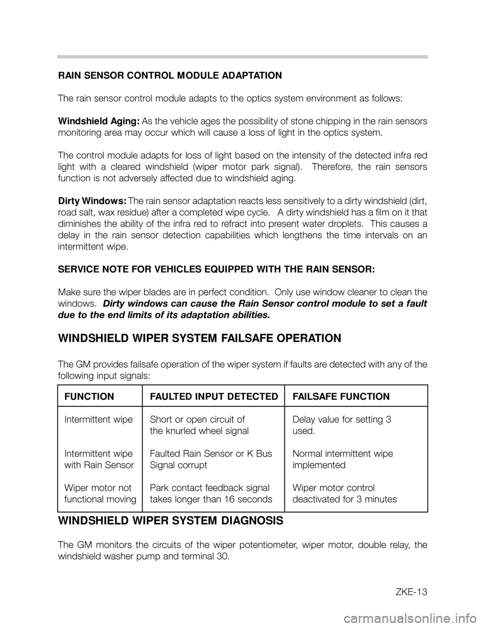
The GM provides failsafe operation of the wiper system if faults are detected with any of the
following input signals:
WINDSHIELD WIPER SYSTEM DIAGNOSIS
The GM monitors the circuits of the wiper potentiometer, wiper motor, double relay, the
windshield washer pump and terminal 30.
FUNCTION FAULTED INPUT DETECTED FAILSAFE FUNCTION
Intermittent wipe Short or open circuit of Delay value for setting 3
the knurled wheel signal used.
Intermittent wipe Faulted Rain Sensor or K Bus Normal intermittent wipe
with Rain Sensor Signal corrupt implemented
Wiper motor not Park contact feedback signal Wiper motor control
functional moving takes longer than 16 seconds deactivated for 3 minutes
Page 14 of 64
ZKE - 14
CENTRAL LOCKING
SYSTEM FEATURES:
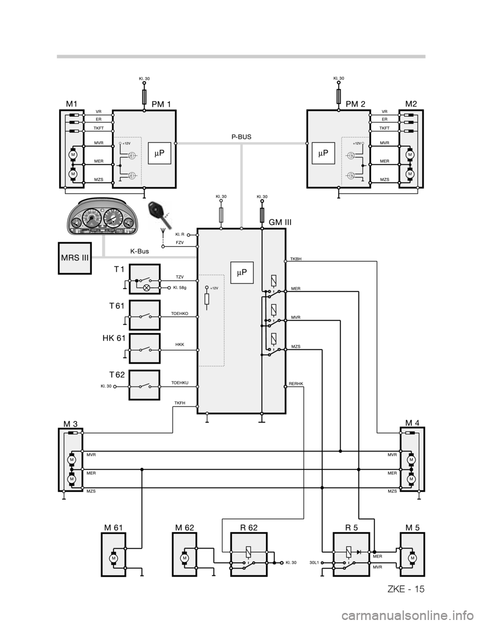
• The Central Locking system controls the door locks, tailgate locks and Fuel Filler Flap
actuators.
• The familiar single/double locking strategy is maintained from previous systems with a
new style door lock mechanismcombined with dual actuator motors similar to that
of the E46 ZKE V system.
• The automatic locking feature activates the door lock actuators when a road speed
signal of 7.5 MPH is detected via the K-Bus. The factory default encoding of this
feature is off, but can be encoded on for individual users with the Key Memory function.
• The Driver’s door lock location is the only point outside of the vehicle where the key can
mechanically control the central locking system functions. The lock incorporates the
familiar overrunning lock cylinder that breaks away and freewheels if an attempt is made
to destroy the lock with a screwdriver, dent puller, etc.
• The selective unlocking feature is maintained. A single unlock request from the driver’s
door with the key or via the remote transmitter unlocks the driver’s door only. A second
unlock request unlocks the remaining doors and trunk. This feature can be modified
for individual users with the new Key Memory capabilities to activate all lock actuators
simultaneously.
• When unlocked, the X5 uppertailgate can be opened by:
- the tailgate button in the center console SZM,
- trunk release switch pad located above the license plate, or
- the trunk release button on an FZV key.
• With the upper tailgate open, the lower tailgate is then opened by depressing the switch
located along it’s top edge.
• GM and EWS 3.3 interface via the K bus to monitor double lock status and to initiate
double lock override. This feature allows the doors to be opened from the inside if an
accepted EWS key is switched on in the ignition when double locked.
Page 15 of 64
ZKE - 15
Page 16 of 64
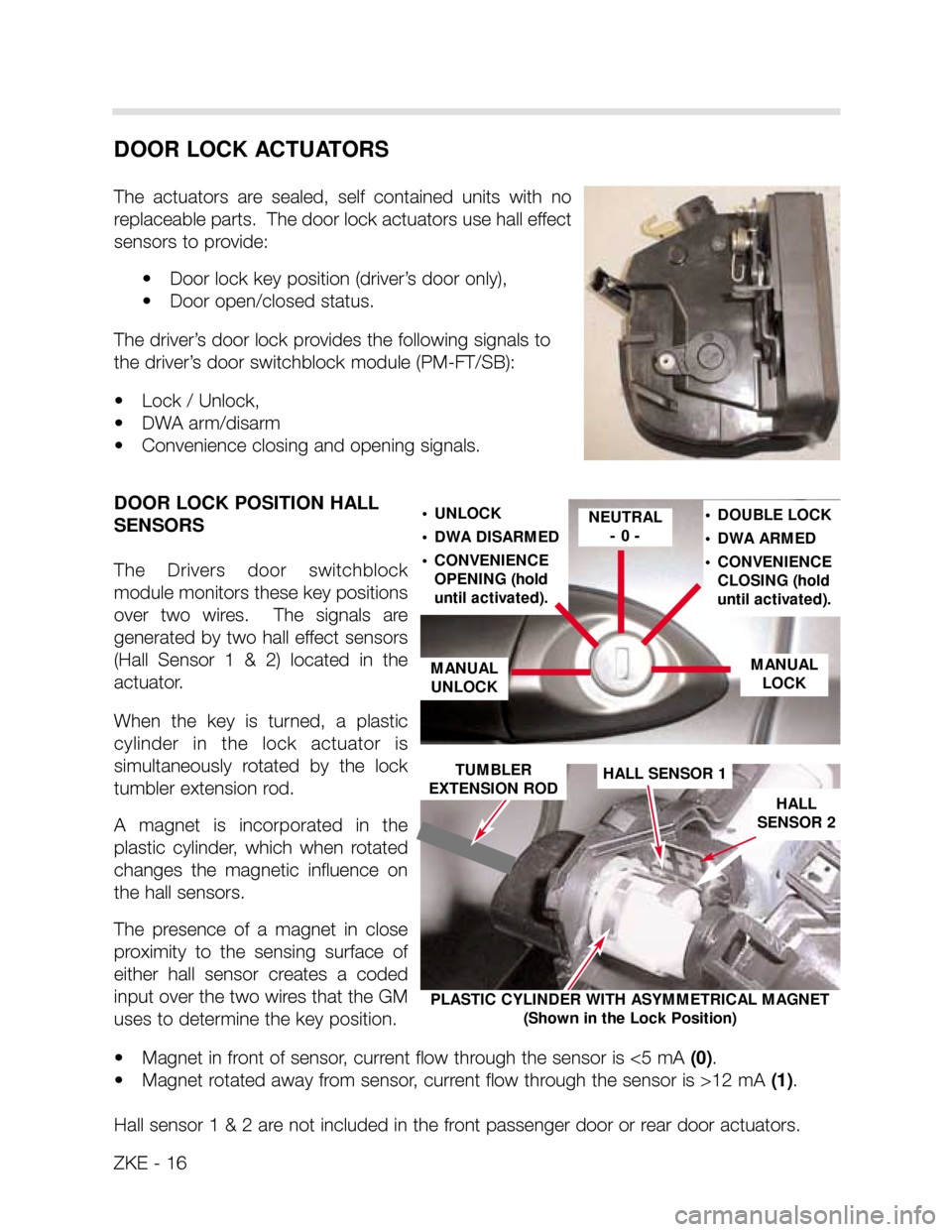
DOOR LOCK ACTUATORS
The actuators are sealed, self contained units with no
replaceable parts. The door lock actuators use hall effect
sensors to provide:
• Door lock key position (driver’s door only),
• Door open/closed status.
The driver’s door lock provides the following signals to
the driver’s door switchblock module (PM-FT/SB):
• Lock / Unlock,
• DWA arm/disarm
• Convenience closing and opening signals.
DOOR LOCK POSITION HALL
SENSORS
The Drivers door switchblock
module monitors these key positions
over two wires. The signals are
generated by two hall effect sensors
(Hall Sensor 1 & 2) located in the
actuator.
When the key is turned, a plastic
cylinder in the lock actuator is
simultaneously rotated by the lock
tumbler extension rod.
A magnet is incorporated in the
plastic cylinder, which when rotated
changes the magnetic influence on
the hall sensors.
The presence of a magnet in close
proximity to the sensing surface of
either hall sensor creates a coded
input over the two wires that the GM
uses to determine the key position.
• Magnet in front of sensor, current flow through the sensor is <5 mA (0).
• Magnet rotated away from sensor, current flow through the sensor is >12 mA (1).
Hall sensor 1 & 2 are not included in the front passenger door or rear door actuators.
ZKE - 16
NEUTRAL
- 0 -
MANUAL
LOCK
HALL SENSOR 1
MANUAL
UNLOCK
• DOUBLE LOCK
DWA ARMED
CONVENIENCE
CLOSING (hold
until activated). UNLOCK
DWA DISARMED
CONVENIENCE
OPENING (hold
until activated).
HALL
SENSOR 2
TUMBLER
EXTENSION ROD
PLASTIC CYLINDER WITH ASYMMETRICAL MAGNET
(Shown in the Lock Position)
Page 17 of 64
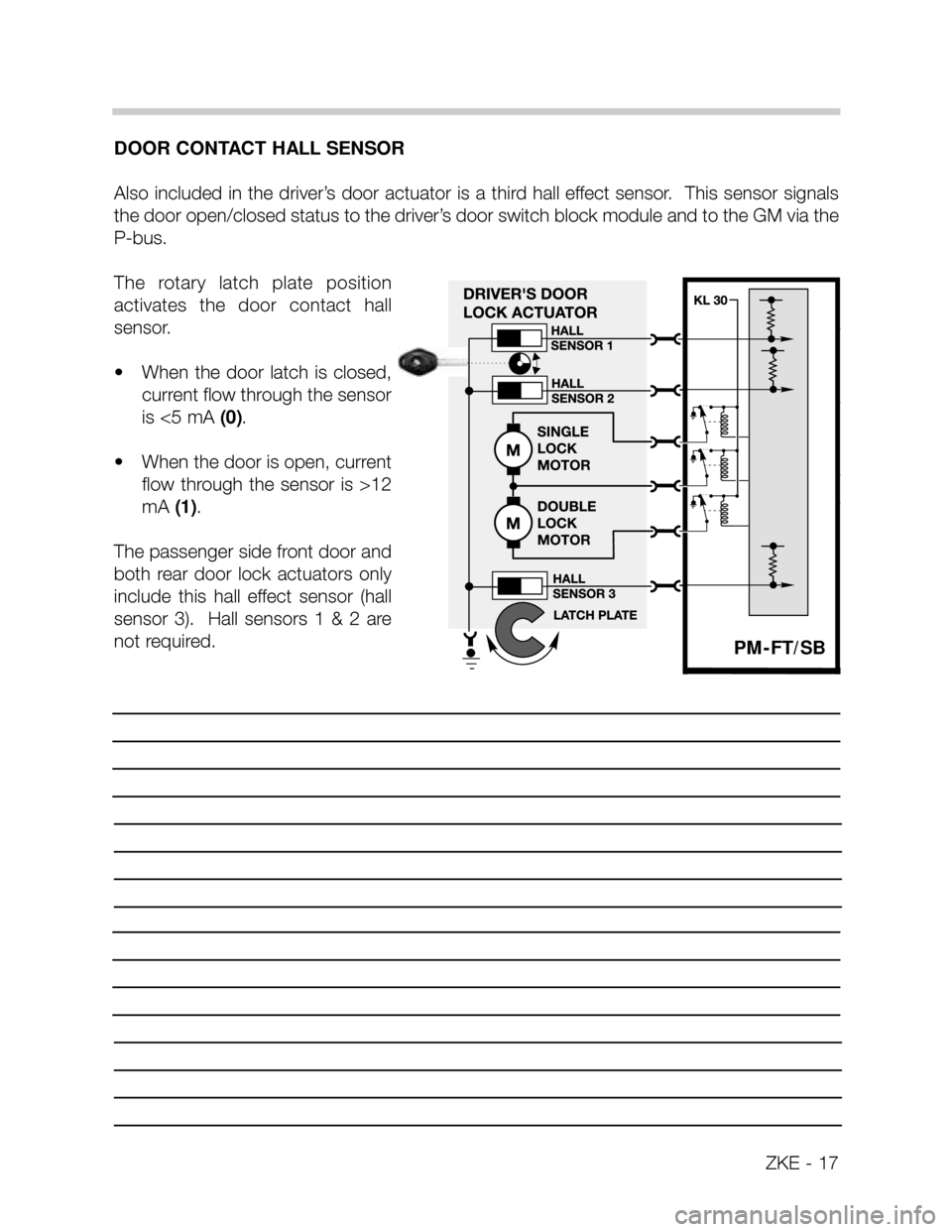
DOOR CONTACT HALL SENSOR
Also included in the driver’s door actuator is a third hall effect sensor. This sensor signals
the door open/closed status to the driver’s door switch block module and to the GM via the
P-bus.
The rotary latch plate position
activates the door contact hall
sensor.
• When the door latch is closed,
current flow through the sensor
is <5 mA (0).
• When the door is open, current
flow through the sensor is >12
mA (1).
The passenger side front door and
both rear door lock actuators only
include this hall effect sensor (hall
sensor 3). Hall sensors 1 & 2 are
not required.
ZKE - 17
PM-FT/SB
Page 18 of 64
ZKE - 18
ACTUATOR MOTOR CONTROL
There are two motors incorporated in each actuator that provide two separate functions:
•Single lock/unlock function. This motor controls the mechanical lock mechanism
when the central lock button is pressed to single lock the vehicle. The mechanism is
locked at this point but can by opened from the interior by pulling an interior door handle
twice or by pressing the central lock button again. When single lock function is
activated, the fuel filler flap actuator is not locked.
•Double lock/unlock function. This motor is activated only when the vehicle is locked
from the outside at the driver’s door lock with a key or when the GM receives a lock
request from the FZV system. In this case the double lock motor is activated
simultaneously with the single lock motor. The function of the double lock motor is to
mechanically offset an internal rod disabling it from unlocking the vehicle from the
interior. This prevents the doors from being unlocked by any means except from an
unlock request at the driver’s door, the FZV remote key or via central lock button.
• Continuous locking/unlocking will initiate a timed arrest of the locking system. The GM counts
each time the locks are actuated. After approximately 12 cycles, the timed arrest is active.
The timed arrest is deactivated one actuator cycle for every 8 seconds until the counter is
reset to 0. The timed arrest is overridden if a crash signal is received from the MRS III.
Page 19 of 64
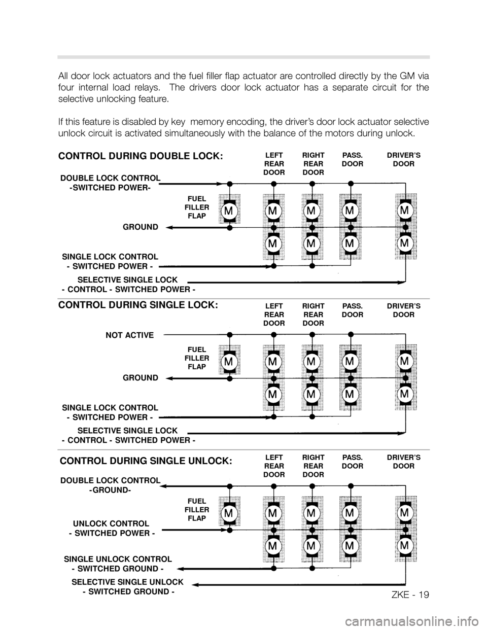
All door lock actuators and the fuel filler flap actuator are controlled directly by the GM via
four internal load relays. The drivers door lock actuator has a separate circuit for the
selective unlocking feature.
If this feature is disabled by key memory encoding, the driver’s door lock actuator selective
unlock circuit is activated simultaneously with the balance of the motors during unlock.
CONTROL DURING DOUBLE LOCK:
CONTROL DURING SINGLE LOCK:
SELECTIVE SINGLE LOCK
- CONTROL - SWITCHED POWER -
SINGLE LOCK CONTROL
- SWITCHED POWER -
GROUND
DOUBLE LOCK CONTROL
-SWITCHED POWER-
FUEL
FILLER
FLAP
LEFT
REAR
DOORRIGHT
REAR
DOORPASS.
DOORDRIVER’S
DOOR
SELECTIVE SINGLE UNLOCK
- SWITCHED GROUND -
SINGLE UNLOCK CONTROL
- SWITCHED GROUND -
UNLOCK CONTROL
- SWITCHED POWER -
DOUBLE LOCK CONTROL
-GROUND-
FUEL
FILLER
FLAP
LEFT
REAR
DOORRIGHT
REAR
DOORPASS.
DOORDRIVER’S
DOOR
SELECTIVE SINGLE LOCK
- CONTROL - SWITCHED POWER -
SINGLE LOCK CONTROL
- SWITCHED POWER -
GROUND
NOT ACTIVE
FUEL
FILLER
FLAP
LEFT
REAR
DOORRIGHT
REAR
DOORPASS.
DOORDRIVER’S
DOOR
ZKE - 19
CONTROL DURING SINGLE UNLOCK:
Page 20 of 64
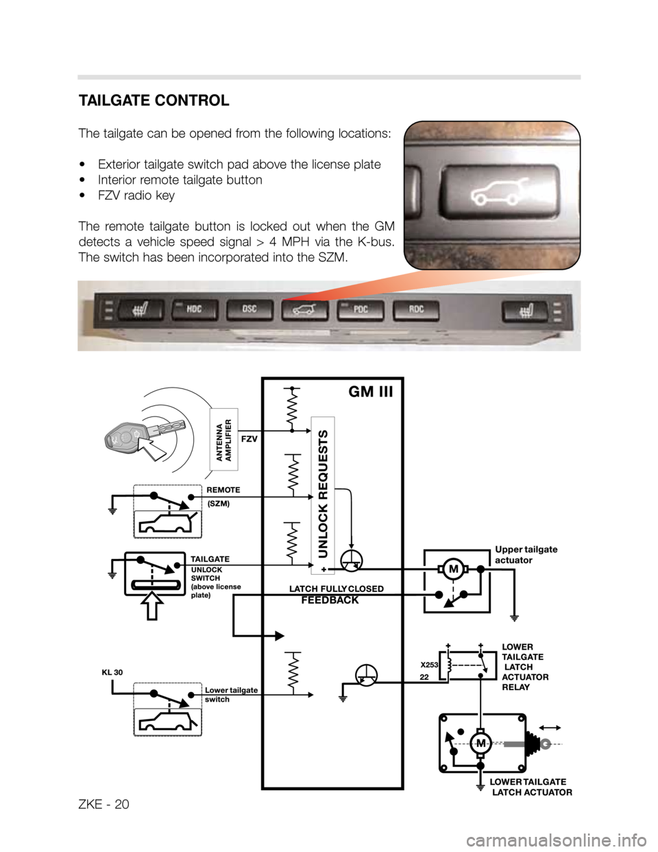
TAILGATE CONTROL
The tailgate can be opened from the following locations:
• Exterior tailgate switch pad above the license plate
• Interior remote tailgate button
• FZV radio key
The remote tailgate button is locked out when the GM
detects a vehicle speed signal > 4 MPH via the K-bus.
The switch has been incorporated into the SZM.
ZKE - 20