Speed sensor BMW X5 2003 E53 M54 Engine Workshop Manual
[x] Cancel search | Manufacturer: BMW, Model Year: 2003, Model line: X5, Model: BMW X5 2003 E53Pages: 48, PDF Size: 2.52 MB
Page 1 of 48
Initial Print Date: 02/2000Revision Date: 6/2000
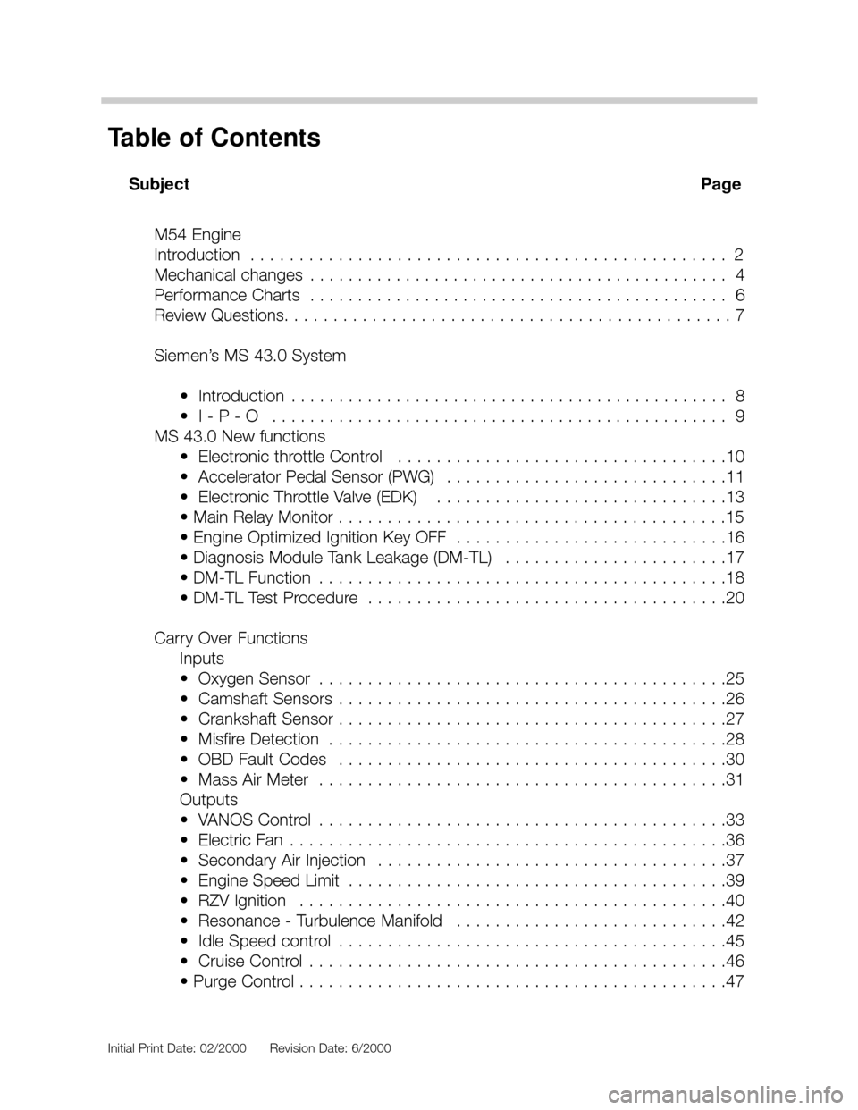
Subject Page
M54 Engine
Introduction . . . . . . . . . . . . . . . . . . . . . . . . . . . . . . . . . . . . . . . . . . . . . . . . . 2
Mechanical changes . . . . . . . . . . . . . . . . . . . . . . . . . . . . . . . . . . . . . . . . . . . . 4
Performance Charts . . . . . . . . . . . . . . . . . . . . . . . . . . . . . . . . . . . . . . . . . . . . 6
Review Questions. . . . . . . . . . . . . . . . . . . . . . . . . . . . . . . . . . . . . . . . . . . . . . 7
Siemen’s MS 43.0 System
• Introduction . . . . . . . . . . . . . . . . . . . . . . . . . . . . . . . . . . . . . . . . . . . . . . 8
• I - P - O . . . . . . . . . . . . . . . . . . . . . . . . . . . . . . . . . . . . . . . . . . . . . . . . 9
MS 43.0 New functions
• Electronic throttle Control . . . . . . . . . . . . . . . . . . . . . . . . . . . . . . . . . .10
• Accelerator Pedal Sensor (PWG) . . . . . . . . . . . . . . . . . . . . . . . . . . . . .11
• Electronic Throttle Valve (EDK) . . . . . . . . . . . . . . . . . . . . . . . . . . . . . .13
• Main Relay Monitor . . . . . . . . . . . . . . . . . . . . . . . . . . . . . . . . . . . . . . . .15
• Engine Optimized Ignition Key OFF . . . . . . . . . . . . . . . . . . . . . . . . . . . .16
• Diagnosis Module Tank Leakage (DM-TL) . . . . . . . . . . . . . . . . . . . . . . .17
• DM-TL Function . . . . . . . . . . . . . . . . . . . . . . . . . . . . . . . . . . . . . . . . . .18
• DM-TL Test Procedure . . . . . . . . . . . . . . . . . . . . . . . . . . . . . . . . . . . . .20
Carry Over Functions
Inputs
• Oxygen Sensor . . . . . . . . . . . . . . . . . . . . . . . . . . . . . . . . . . . . . . . . . .25
• Camshaft Sensors . . . . . . . . . . . . . . . . . . . . . . . . . . . . . . . . . . . . . . . .26
• Crankshaft Sensor . . . . . . . . . . . . . . . . . . . . . . . . . . . . . . . . . . . . . . . .27
• Misfire Detection . . . . . . . . . . . . . . . . . . . . . . . . . . . . . . . . . . . . . . . . .28
• OBD Fault Codes . . . . . . . . . . . . . . . . . . . . . . . . . . . . . . . . . . . . . . . .30
• Mass Air Meter . . . . . . . . . . . . . . . . . . . . . . . . . . . . . . . . . . . . . . . . . .31
Outputs
• VANOS Control . . . . . . . . . . . . . . . . . . . . . . . . . . . . . . . . . . . . . . . . . .33
• Electric Fan . . . . . . . . . . . . . . . . . . . . . . . . . . . . . . . . . . . . . . . . . . . . .36
• Secondary Air Injection . . . . . . . . . . . . . . . . . . . . . . . . . . . . . . . . . . . .37
• Engine Speed Limit . . . . . . . . . . . . . . . . . . . . . . . . . . . . . . . . . . . . . . .39
• RZV Ignition . . . . . . . . . . . . . . . . . . . . . . . . . . . . . . . . . . . . . . . . . . . .40
• Resonance - Turbulence Manifold . . . . . . . . . . . . . . . . . . . . . . . . . . . .42
• Idle Speed control . . . . . . . . . . . . . . . . . . . . . . . . . . . . . . . . . . . . . . . .45
• Cruise Control . . . . . . . . . . . . . . . . . . . . . . . . . . . . . . . . . . . . . . . . . . .46
• Purge Control . . . . . . . . . . . . . . . . . . . . . . . . . . . . . . . . . . . . . . . . . . . .47
Table of Contents
Page 10 of 48
10
M54engMS43/ST036/6/2000
MS 43 NEW FUNCTIONS
ELECTRONIC THROTTLE SYSTEM - EML
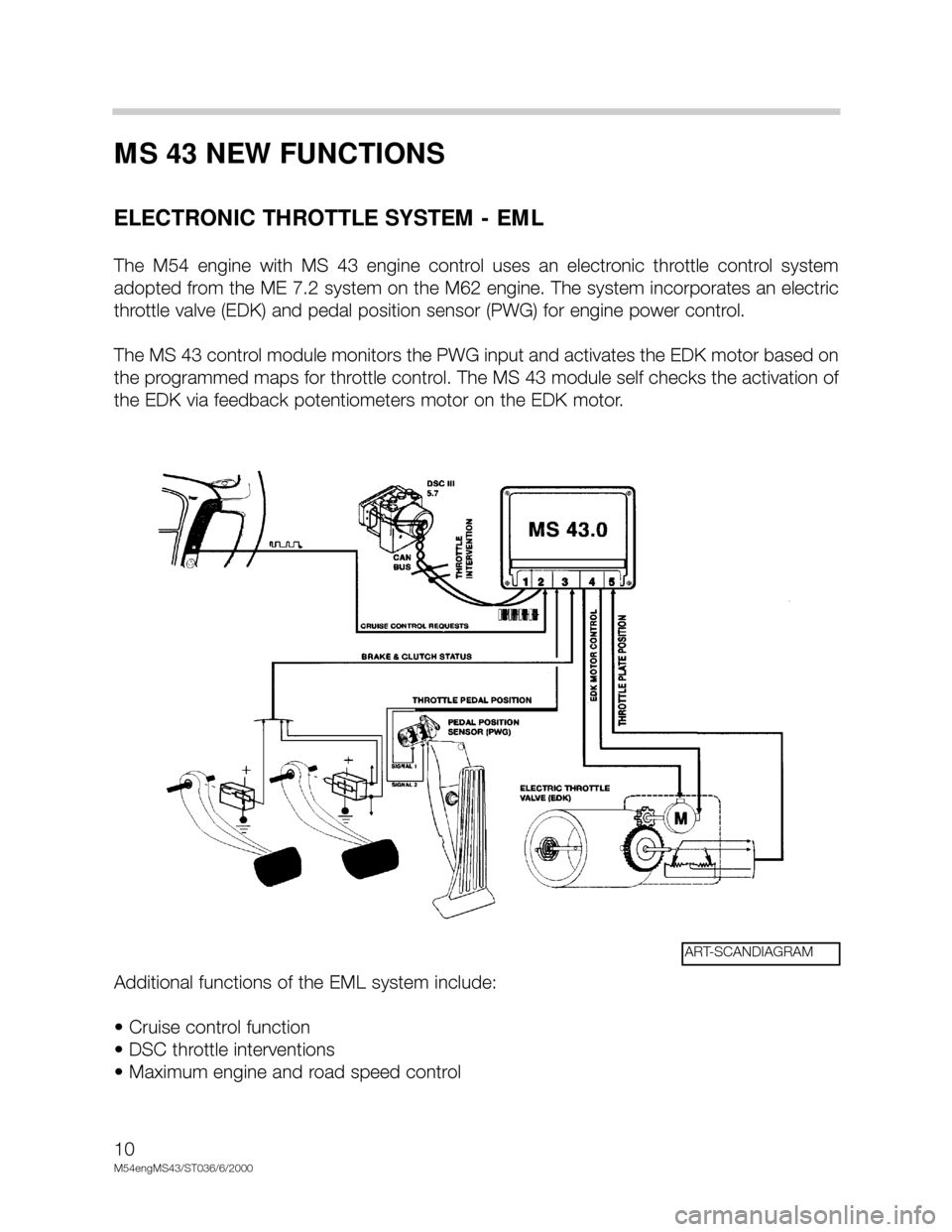
The M54 engine with MS 43 engine control uses an electronic throttle control system
adopted from the ME 7.2 system on the M62 engine. The system incorporates an electric
throttle valve (EDK) and pedal position sensor (PWG) for engine power control.
The MS 43 control module monitors the PWG input and activates the EDK motor based on
the programmed maps for throttle control. The MS 43 module self checks the activation of
the EDK via feedback potentiometers motor on the EDK motor.
Additional functions of the EML system include:
• Cruise control function
• DSC throttle interventions
• Maximum engine and road speed control
ART-SCANDIAGRAM
Page 26 of 48
26
M54engMS43/ST036/6/2000
CAMSHAFT SENSOR
-INTAKE AND EXHAUST CAMSHAFTS
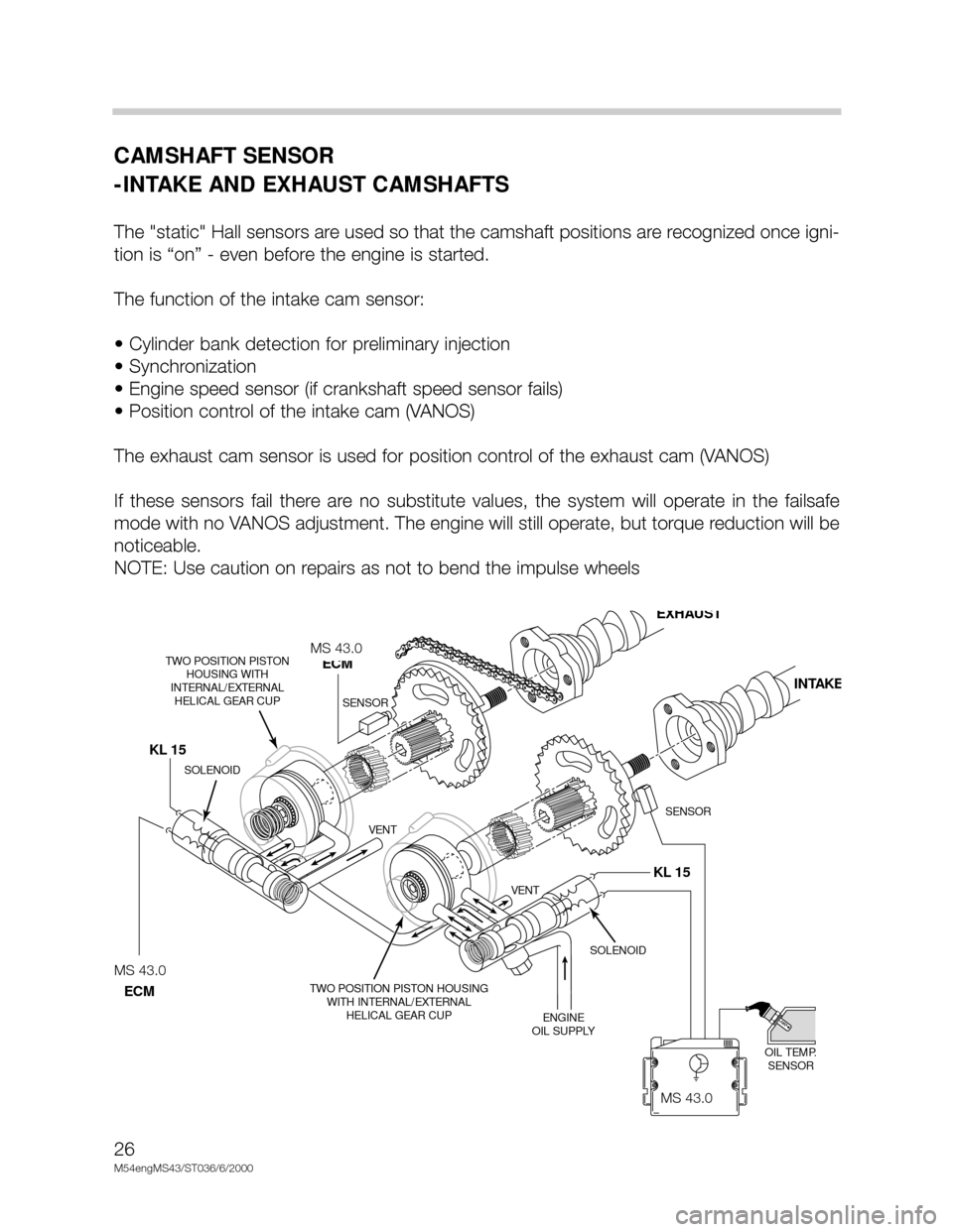
The "static" Hall sensors are used so that the camshaft positions are recognized once igni-
tion is “on” - even before the engine is started.
The function of the intake cam sensor:
• Cylinder bank detection for preliminary injection
• Synchronization
• Engine speed sensor (if crankshaft speed sensor fails)
• Position control of the intake cam (VANOS)
The exhaust cam sensor is used for position control of the exhaust cam (VANOS)
If these sensors fail there are no substitute values, the system will operate in the failsafe
mode with no VANOS adjustment. The engine will still operate, but torque reduction will be
noticeable.
NOTE: Use caution on repairs as not to bend the impulse wheels
KL 15 KL 15
MS42.0
SOLENOID
OIL TEMP.
SENSOR TWO POSITION PISTON HOUSING
WITH INTERNAL/EXTERNAL
HELICAL GEAR CUP TWO POSITION PISTON
HOUSING WITH
INTERNAL/EXTERNAL
HELICAL GEAR CUP
ENGINE
OIL SUPPLY VENT VENT
SOLENOID
SENSOR SENSOR
MS42
ECM
EXHAUST
INTAKE
MS42.0
ECM
MS 43.0
MS 43.0
MS 43.0
Page 29 of 48
29
M54engMS43/ST036/6/20000
EMISSIONS RELEVANT:
During an interval of 1000 crankshaft revolutions
the misfire events of all cylinders are
added and if the sum is greater than a predetermined value a fault will be set identifying the
particular cylinder(s). The “Service Engine Soon” light will be illuminated during and after
the second cycle if the fault is again present.
CATALYST DAMAGING:
During an interval of 200 crankshaft revolutions
the misfire events of all cylinders are added
and if the sum is greater than a predetermined value a fault will be set identifying the par-
ticular cylinders(s). The “Service Engine Soon” lamp:
• On vehicles with a Siemens Control Module (M54 engines) - the lamp will immediately go
to a steady illumination since fuel to the injector(s) is removed. Fuel cut-off to the cylin-
der will resume after several (
>>7) periods of decel if crankshaft sensor adaptation is suc-
cessfully completed or the engine is shut-off and restarted.
In each case the number of misfire events permitted is dependent on engine speed, load
and temperature map.
The process of misfire detection continues well after the diagnostic drive cycle requirements
have been completed. Misfire detection is an on-going monitoring process
that is only dis-
continued under certain conditions.
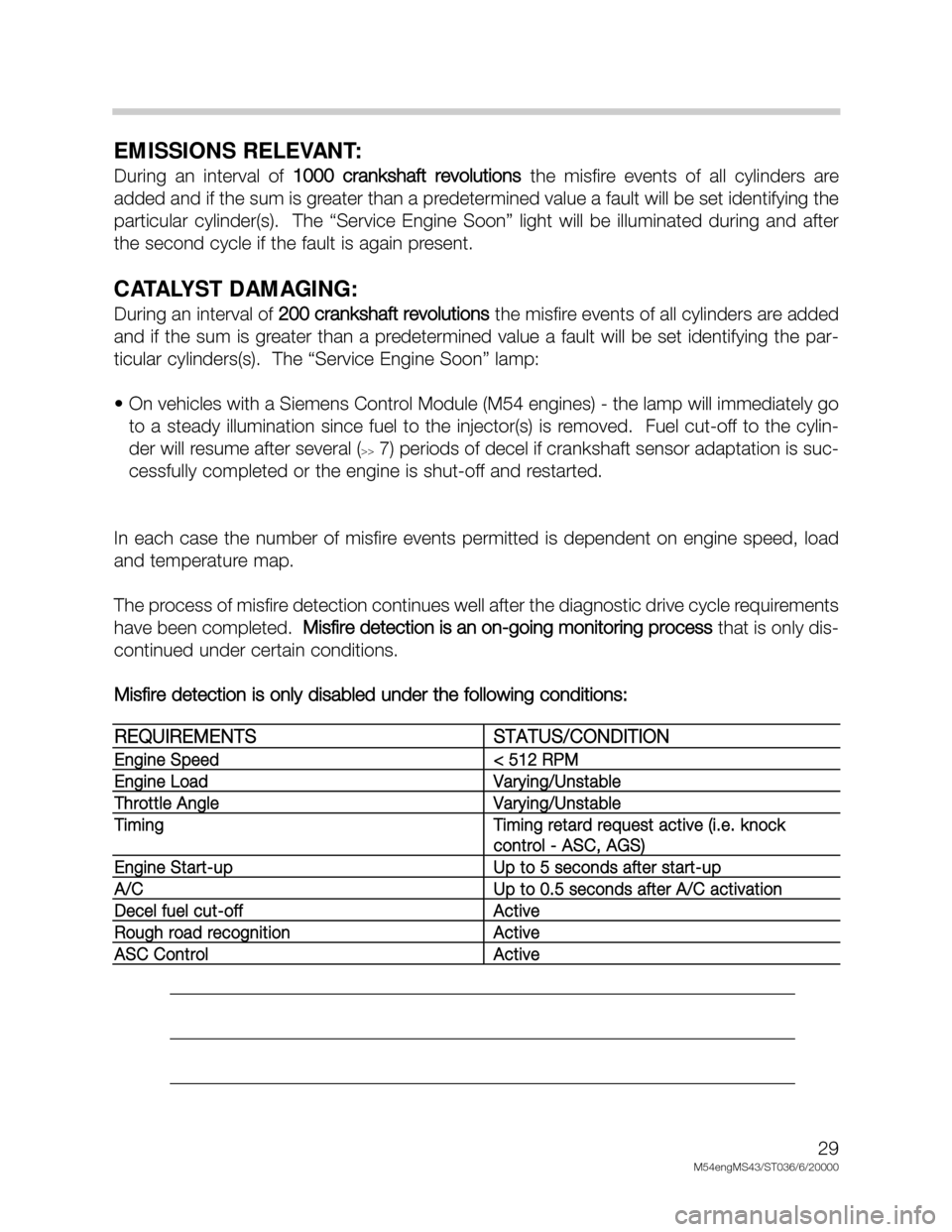
Misfire detection is only disabled under the following conditions:
___________________________________________________________________
___________________________________________________________________
___________________________________________________________________
REQUIREMENTSSTATUS/CONDITION
Engine Speed< 512 RPM
Engine LoadVarying/Unstable
Throttle AngleVarying/Unstable
TimingTiming retard request active (i.e. knock
control - ASC, AGS)
Engine Start-upUp to 5 seconds after start-up
A/CUp to 0.5 seconds after A/C activation
Decel fuel cut-offActive
Rough road recognitionActive
ASC ControlActive
Page 32 of 48
32
M54engMS43/ST036/6/2000
MS 43 CARRY OVER FUNCTIONS
OUTPUT FUNCTIONS -VANOS CONTROL
With the double VANOS system, the valve timing is changed on both the intake and the
exhaust camshafts.
Double VANOS provides the following benefits:
• Torque increase in the low to mid (1500 - 2000 RPM) range without power loss in the
upper RPM range.
• Less incomplete combustion when idling due to less camshaft overlap (also improves
idle speed characteristics).
• Internal exhaust gas recirculation (EGR) in the part load range (reduces NOx and post-
combustion of residual gasses in the exhaust)
• Rapid catalyst warm up and lower “raw” emissions after cold start.
• Reduction in fuel consumption
Double VANOS consists of the following parts:
• Intake and exhaust camshafts with helical gear insert
• Sprockets with adjustable gears
• VANOS actuators for each camshaft
• 2 three-way solenoid switching valves
• 2 impulse wheels for detecting camshaft position
• 2 camshaft position sensors (Hall effect)
The “initial” timing is set by gear positioning (refer to the Repair Instructions for details) and
the chain tensioner. As with the previous VANOS, the hydraulically controlled actuators
move the helical geared cups to regulate camshaft timing. The angled teeth of the helical
gears cause the pushing
movement of the helical cup to be converted into a rotational
movement. This rotational movement is added to the turning of the camshafts and cause
the camshafts to “advance” or “retard”. The adjustment rate is dependent oil temperature,
oil pressure, and engine RPM.
Page 37 of 48
37
M54engMS43/ST036/6/20000
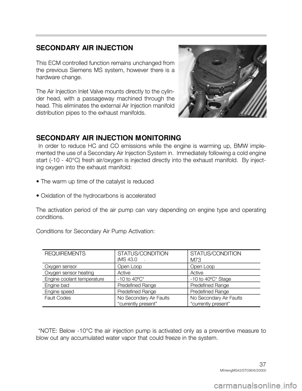
SECONDARY AIR INJECTION
This ECM controlled function remains unchanged from
the previous Siemens MS system, however there is a
hardware change.
The Air Injection Inlet Valve mounts directly to the cylin-
der head, with a passageway machined through the
head. This eliminates the external Air Injection manifold
distribution pipes to the exhaust manifolds.
SECONDARY AIR INJECTION MONITORING
In order to reduce HC and CO emissions while the engine is warming up, BMW imple-
mented the use of a Secondary Air Injection System in. Immediately following a cold engine
start (-10 - 40°C) fresh air/oxygen is injected directly into the exhaust manifold. By inject-
ing oxygen into the exhaust manifold:
• The warm up time of the catalyst is reduced
• Oxidation of the hydrocarbons is accelerated
The activation period of the air pump can vary depending on engine type and operating
conditions.
Conditions for Secondary Air Pump Activation:
*NOTE: Below -10°C the air injection pump is activated only as a preventive measure to
blow out any accumulated water vapor that could freeze in the system.
REQUIREMENTS STATUS/CONDITION
M52 & M44STATUS/CONDITION
M73
Oxygen sensor Open Loop Open Loop
Oxygen sensor heating Active Active
Engine coolant temperature -10 to 40ºC* -10 to 40ºC* Stage
Engine bad Predefined Range Predefined Range
Engine speed Predefined Range Predefined Range
Fault Codes No Secondary Air Faults
“currently present”
No Secondary Air Faults
“currently present”
MS 43.0
Page 46 of 48
46
M54engMS43/ST036/6/2000
CRUISE CONTROL
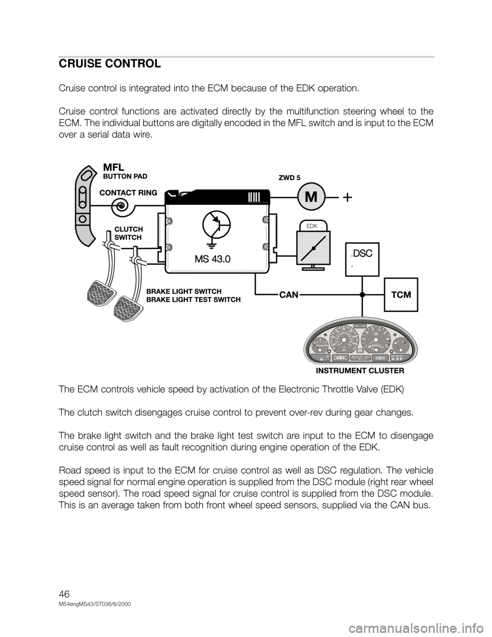
Cruise control is integrated into the ECM because of the EDK operation.
Cruise control functions are activated directly by the multifunction steering wheel to the
ECM. The individual buttons are digitally encoded in the MFL switch and is input to the ECM
over a serial data wire.
The ECM controls vehicle speed by activation of the Electronic Throttle Valve (EDK)
The clutch switch disengages cruise control to prevent over-rev during gear changes.
The brake light switch and the brake light test switch are input to the ECM to disengage
cruise control as well as fault recognition during engine operation of the EDK.
Road speed is input to the ECM for cruise control as well as DSC regulation. The vehicle
speed signal for normal engine operation is supplied from the DSC module (right rear wheel
speed sensor). The road speed signal for cruise control is supplied from the DSC module.
This is an average taken from both front wheel speed sensors, supplied via the CAN bus.
DSCMS 43.0
EDK