Engine light BMW X5 2011 E70 User Guide
[x] Cancel search | Manufacturer: BMW, Model Year: 2011, Model line: X5, Model: BMW X5 2011 E70Pages: 312, PDF Size: 8.91 MB
Page 71 of 312
Controls
69Reference
At a glance
Driving tips
Communications
Navigation
Entertainment
Mobility
cruise control will, within limits, adjust your
vehicle's speed automatically so that you can
flow with the traffic without having to make con-
stant adjustments. If, for example, while cruis-
ing at the selected speed, you begin to
approach a slower vehicle ahead of you in the
same lane, the system will reduce your vehicle's
speed to the same as that of the vehicle ahead
to maintain your selected distance setting. You
can vary the following distance, which will vary
with speed. Based on your selected distance
setting, the system automatically decreases the
throttle setting and lightly applies the brakes if
necessary. In addition, if the vehicle ahead of
you slows to a complete stop, the system can
follow this action within the given scope and
can also accelerate from a complete stop if the
vehicle ahead of you drives off again shortly
thereafter. During braking, your vehicle brake
lamps will automatically illuminate to alert a fol-
lowing driver to take action. In addition, it may
be necessary for your vehicle to downshift the
automatic transmission to maintain the dis-
tance setting selected. As soon as the road in
front of you has no moving vehicles, the system
will accelerate to your desired speed. This set
speed is also maintained on downhill grades,
however the vehicle speed can drop below the
set speed when driving uphill if the engine out-
put is not sufficient.
Active cruise control cannot detect stop
signs, red lights, or any object that is
stopped or is blocking the road.
Active cruise control is not and must not be
used as a collision avoidance/warning system.
Since this active cruise control system is a new
technology and operates differently from con-
ventional cruise control systems to which you
may be accustomed, it is necessary that you
read all of the pages relating to this system
before use. Carefully read and observe the
information on the system limitations beginning
on page73 to obtain a good command of the
system and its range of applications.
the brake pedal, a somewhat different braking
feel results.
Professional navigation system*
If the vehicle is equipped with a Professional
navigation system, the system adapts the
acceleration and deceleration behavior of the
vehicle to the road on which you are currently
driving.
To ensure that the system has the latest
information on the course of the road, use
the most recent version of the navigation
data.<
If the vehicle position is unknown, e. g. if you
have left the region covered by the map, the
navigation system ceases to influence vehicle
behavior.
Applications
Please try the system first during sparse traffic
and clear road conditions so that you can get
used to the system. After you have experience
and understand the system, only then use it
during normal traffic.
As with conventional cruise control systems,
active cruise control in no way reduces or sub-
stitutes for the driver's own personal experi-
ence, responsibility, alertness and awareness in
adjusting speed, braking or otherwise control-
ling the vehicle. The driver should decide when
to use the system on the basis of road, traffic,
visibility, and weather conditions. Active cruise
control is intended for use on highway-type
roadways where traffic is moving relatively
smoothly as well as in slow-moving traffic con-
gestion. Do not use the system in city driving; in
complex driving situations; heavy traffic such as
during rush hour; on curvy, winding roads, slip-
pery roads or roads with sharp curves such as
highway off-ramps; during inclement weather
such as snow, strong rain or fog; or when enter-
ing interchanges, service/parking areas or toll
booths. It is also important to regulate your
vehicle's speed and distance setting within
applicable legal limits. Always be ready to take
Page 73 of 312
Controls
71Reference
At a glance
Driving tips
Communications
Navigation
Entertainment
Mobility
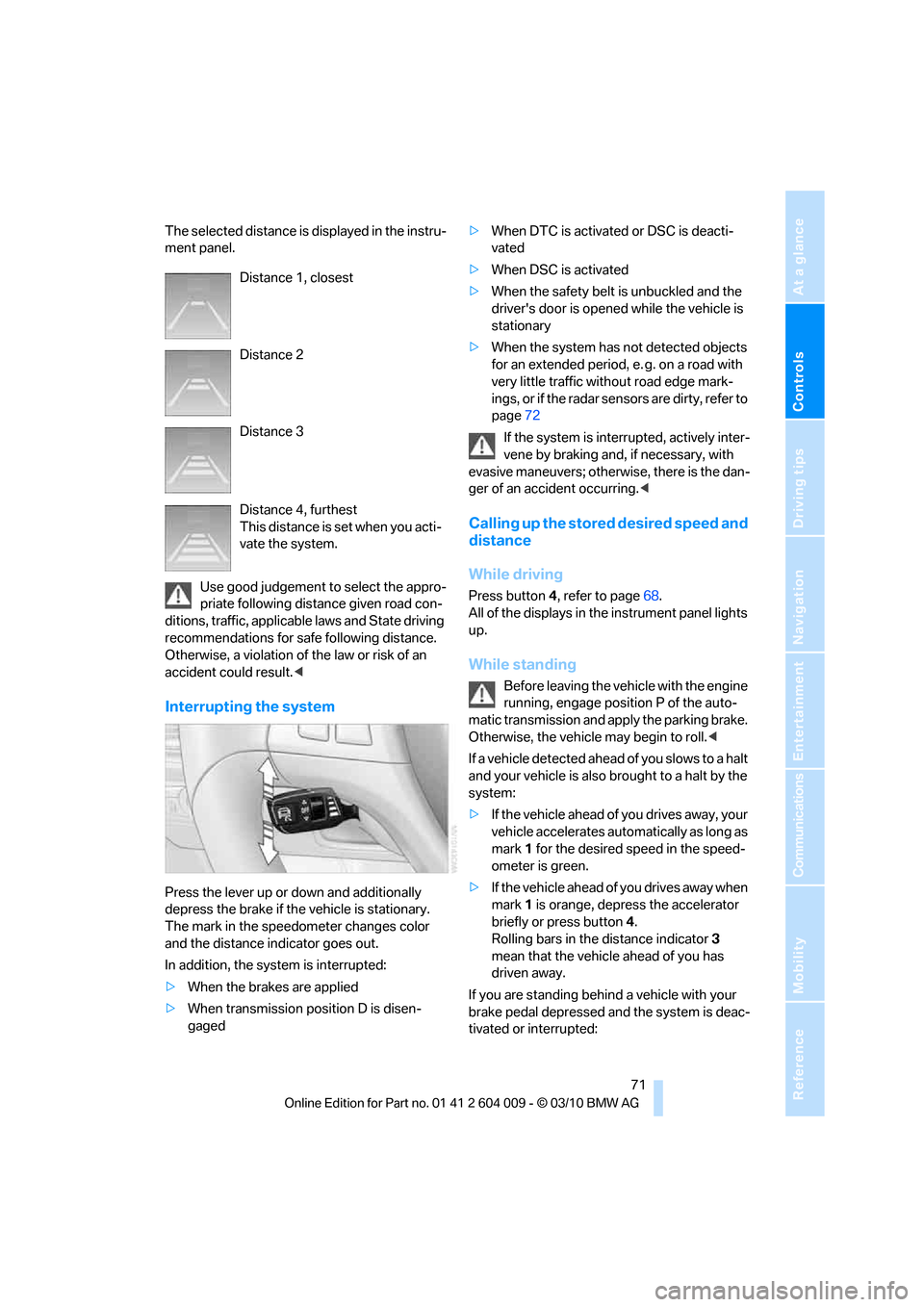
The selected distance is displayed in the instru-
ment panel.
Use good judgement to select the appro-
priate following distance given road con-
ditions, traffic, applicable laws and State driving
recommendations for safe following distance.
Otherwise, a violation of the law or risk of an
accident could result.<
Interrupting the system
Press the lever up or down and additionally
depress the brake if the vehicle is stationary.
The mark in the speedometer changes color
and the distance indicator goes out.
In addition, the system is interrupted:
>When the brakes are applied
>When transmission position D is disen-
gaged>When DTC is activated or DSC is deacti-
vated
>When DSC is activated
>When the safety belt is unbuckled and the
driver's door is opened while the vehicle is
stationary
>When the system has not detected objects
for an extended period, e. g. on a road with
very little traffic without road edge mark-
ings, or if the radar sensors are dirty, refer to
page72
If the system is interrupted, actively inter-
vene by braking and, if necessary, with
evasive maneuvers; otherwise, there is the dan-
ger of an accident occurring.<
Calling up the stored desired speed and
distance
While driving
Press button4, refer to page68.
All of the displays in the instrument panel lights
up.
While standing
Before leaving the vehicle with the engine
running, engage position P of the auto-
matic transmission and apply the parking brake.
Otherwise, the vehicle may begin to roll.<
If a vehicle detected ahead of you slows to a halt
and your vehicle is also brought to a halt by the
system:
>If the vehicle ahead of you drives away, your
vehicle accelerates automatically as long as
mark 1 for the desired speed in the speed-
ometer is green.
>If the vehicle ahead of you drives away when
mark 1 is orange, depress the accelerator
briefly or press button 4.
Rolling bars in the distance indicator 3
mean that the vehicle ahead of you has
driven away.
If you are standing behind a vehicle with your
brake pedal depressed and the system is deac-
tivated or interrupted: Distance 1, closest
Distance 2
Distance 3
Distance 4, furthest
This distance is set when you acti-
vate the system.
Page 79 of 312
Controls
77Reference
At a glance
Driving tips
Communications
Navigation
Entertainment
Mobility
Tachometer
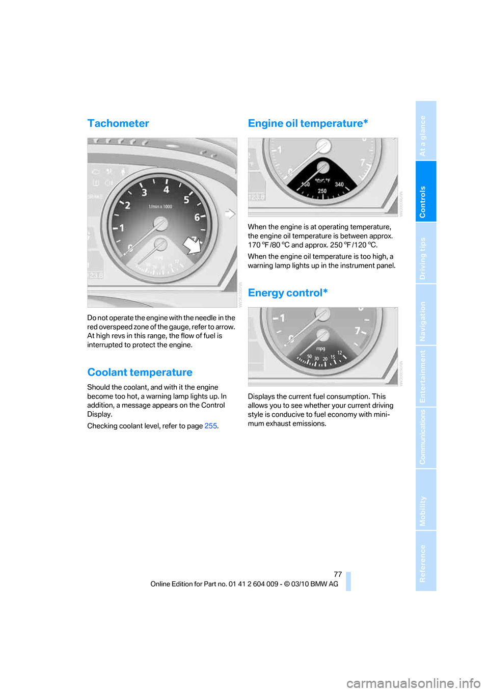
Do not operate the engine with the needle in the
red overspeed zone of the gauge, refer to arrow.
At high revs in this range, the flow of fuel is
interrupted to protect the engine.
Coolant temperature
Should the coolant, and with it the engine
become too hot, a warning lamp lights up. In
addition, a message appears on the Control
Display.
Checking coolant level, refer to page255.
Engine oil temperature*
When the engine is at operating temperature,
the engine oil temperature is between approx.
1707/806 and approx. 2507/1206.
When the engine oil temperature is too high, a
warning lamp lights up in the instrument panel.
Energy control*
Displays the current fuel consumption. This
allows you to see whether your current driving
style is conducive to fuel economy with mini-
mum exhaust emissions.
Page 80 of 312
Controls Overview
78
Fuel gauge
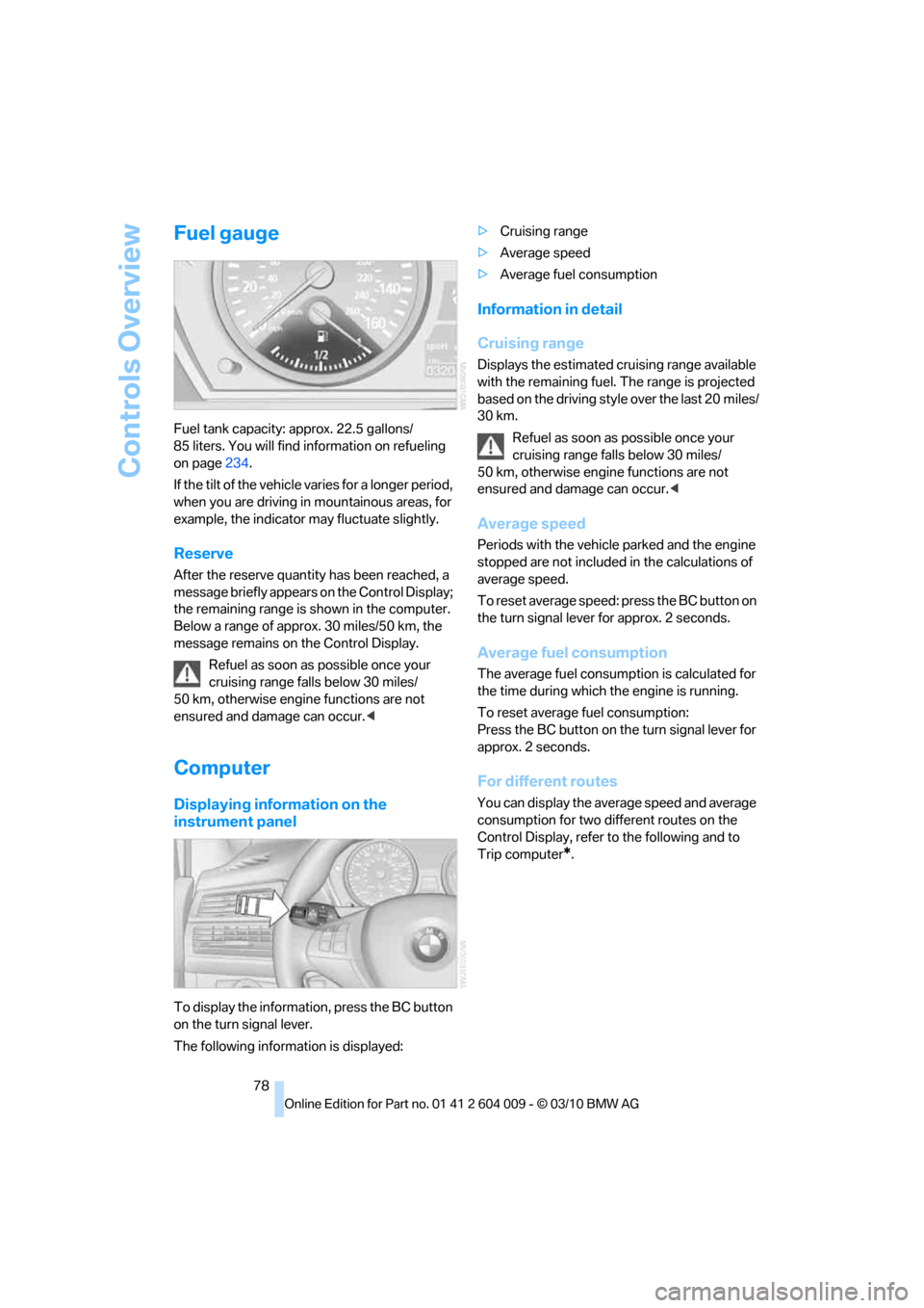
Fuel tank capacity: approx. 22.5 gallons/
85 liters. You will find information on refueling
on page234.
If the tilt of the vehicle varies for a longer period,
when you are driving in mountainous areas, for
example, the indicator may fluctuate slightly.
Reserve
After the reserve quantity has been reached, a
message briefly appears on the Control Display;
the remaining range is shown in the computer.
Below a range of approx. 30 miles/50 km, the
message remains on the Control Display.
Refuel as soon as possible once your
cruising range falls below 30 miles/
50 km, otherwise engine functions are not
ensured and damage can occur.<
Computer
Displaying information on the
instrument panel
To display the information, press the BC button
on the turn signal lever.
The following information is displayed:>Cruising range
>Average speed
>Average fuel consumption
Information in detail
Cruising range
Displays the estimated cruising range available
with the remaining fuel. The range is projected
based on the driving style over the last 20 miles/
30 km.
Refuel as soon as possible once your
cruising range falls below 30 miles/
50 km, otherwise engine functions are not
ensured and damage can occur.<
Average speed
Periods with the vehicle parked and the engine
stopped are not included in the calculations of
average speed.
To reset average speed: press the BC button on
the turn signal lever for approx. 2 seconds.
Average fuel consumption
The average fuel consumption is calculated for
the time during which the engine is running.
To reset average fuel consumption:
Press the BC button on the turn signal lever for
approx. 2 seconds.
For different routes
You can display the average speed and average
consumption for two different routes on the
Control Display, refer to the following and to
Trip computer
*.
Page 92 of 312
Technology for comfort, convenience and safety
90
Malfunction
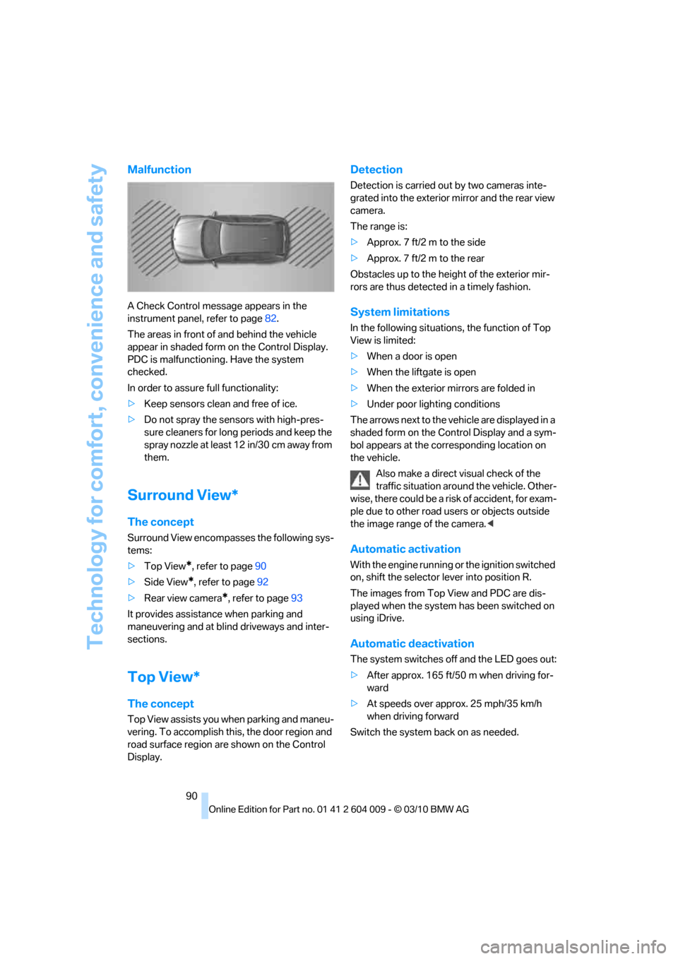
A Check Control message appears in the
instrument panel, refer to page82.
The areas in front of and behind the vehicle
appear in shaded form on the Control Display.
PDC is malfunctioning. Have the system
checked.
In order to assure full functionality:
>Keep sensors clean and free of ice.
>Do not spray the sensors with high-pres-
sure cleaners for long periods and keep the
spray nozzle at least 12 in/30 cm away from
them.
Surround View*
The concept
Surround View encompasses the following sys-
tems:
>Top View
*, refer to page90
>Side View
*, refer to page92
>Rear view camera
*, refer to page93
It provides assistance when parking and
maneuvering and at blind driveways and inter-
sections.
Top View*
The concept
Top View assists you when parking and maneu-
vering. To accomplish this, the door region and
road surface region are shown on the Control
Display.
Detection
Detection is carried out by two cameras inte-
grated into the exterior mirror and the rear view
camera.
The range is:
>Approx. 7 ft/2 m to the side
>Approx. 7 ft/2 m to the rear
Obstacles up to the height of the exterior mir-
rors are thus detected in a timely fashion.
System limitations
In the following situations, the function of Top
View is limited:
>When a door is open
>When the liftgate is open
>When the exterior mirrors are folded in
>Under poor lighting conditions
The arrows next to the vehicle are displayed in a
shaded form on the Control Display and a sym-
bol appears at the corresponding location on
the vehicle.
Also make a direct visual check of the
traffic situation around the vehicle. Other-
wise, there could be a risk of accident, for exam-
ple due to other road users or objects outside
the image range of the camera.<
Automatic activation
With the engine running or the ignition switched
on, shift the selector lever into position R.
The images from Top View and PDC are dis-
played when the system has been switched on
using iDrive.
Automatic deactivation
The system switches off and the LED goes out:
>After approx. 165 ft/50 m when driving for-
ward
>At speeds over approx. 25 mph/35 km/h
when driving forward
Switch the system back on as needed.
Page 95 of 312
Controls
93Reference
At a glance
Driving tips
Communications
Navigation
Entertainment
Mobility
Cameras
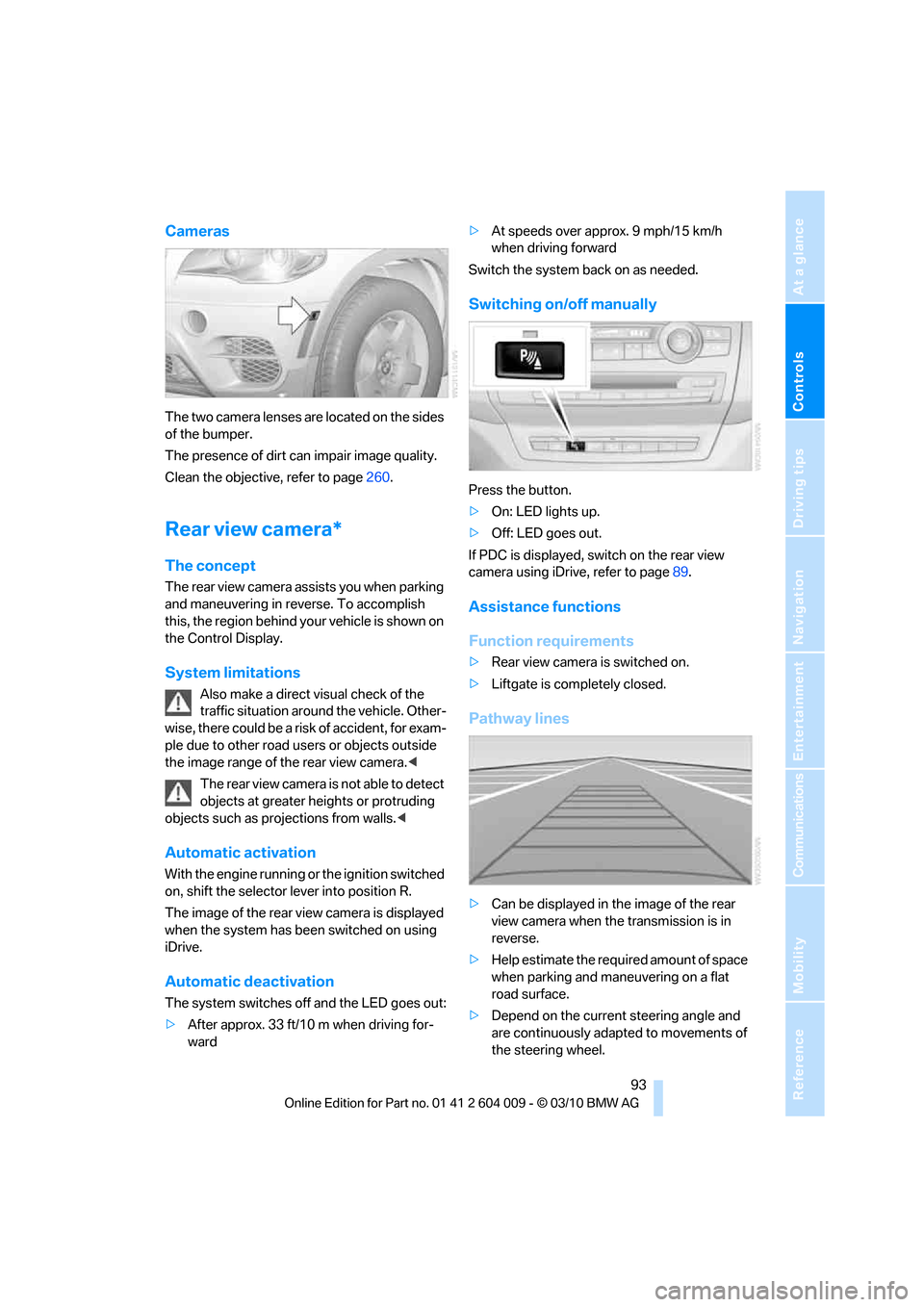
The two camera lenses are located on the sides
of the bumper.
The presence of dirt can impair image quality.
Clean the objective, refer to page260.
Rear view camera*
The concept
The rear view camera assists you when parking
and maneuvering in reverse. To accomplish
this, the region behind your vehicle is shown on
the Control Display.
System limitations
Also make a direct visual check of the
traffic situation around the vehicle. Other-
wise, there could be a risk of accident, for exam-
ple due to other road users or objects outside
the image range of the rear view camera.<
T he r e a r v i e w c a m e r a i s n o t a b l e t o de t e c t
objects at greater heights or protruding
objects such as projections from walls.<
Automatic activation
With the engine running or the ignition switched
on, shift the selector lever into position R.
The image of the rear view camera is displayed
when the system has been switched on using
iDrive.
Automatic deactivation
The system switches off and the LED goes out:
>After approx. 33 ft/10 m when driving for-
ward>At speeds over approx. 9 mph/15 km/h
when driving forward
Switch the system back on as needed.
Switching on/off manually
Press the button.
>On: LED lights up.
>Off: LED goes out.
If PDC is displayed, switch on the rear view
camera using iDrive, refer to page89.
Assistance functions
Function requirements
>Rear view camera is switched on.
>Liftgate is completely closed.
Pathway lines
>Can be displayed in the image of the rear
view camera when the transmission is in
reverse.
>Help estimate the required amount of space
when parking and maneuvering on a flat
road surface.
>Depend on the current steering angle and
are continuously adapted to movements of
the steering wheel.
Page 102 of 312
Technology for comfort, convenience and safety
100
Function requirements
The system must have been initialized while the
tire inflation pressure was correct; otherwise,
reliable signaling of a flat tire is not ensured.
Initialize the system after every correction of the
tire inflation pressure and after every tire or
wheel change.
System limits
Sudden serious tire damage caused by
external influences cannot be indicated in
advance.<
A natural, even pressure loss in all four tires
cannot be detected. Therefore, check the tire
inflation pressure regularly.
In the following situations, the system could be
delayed or malfunction:
>System has not been initialized
>Driving on snowy or slippery road surface
>Sporty driving style: slip in the drive wheels,
high lateral acceleration
>Driving with snow chains
*
When you are driving with the compact wheel*
the Flat Tire Monitor is unable to function.
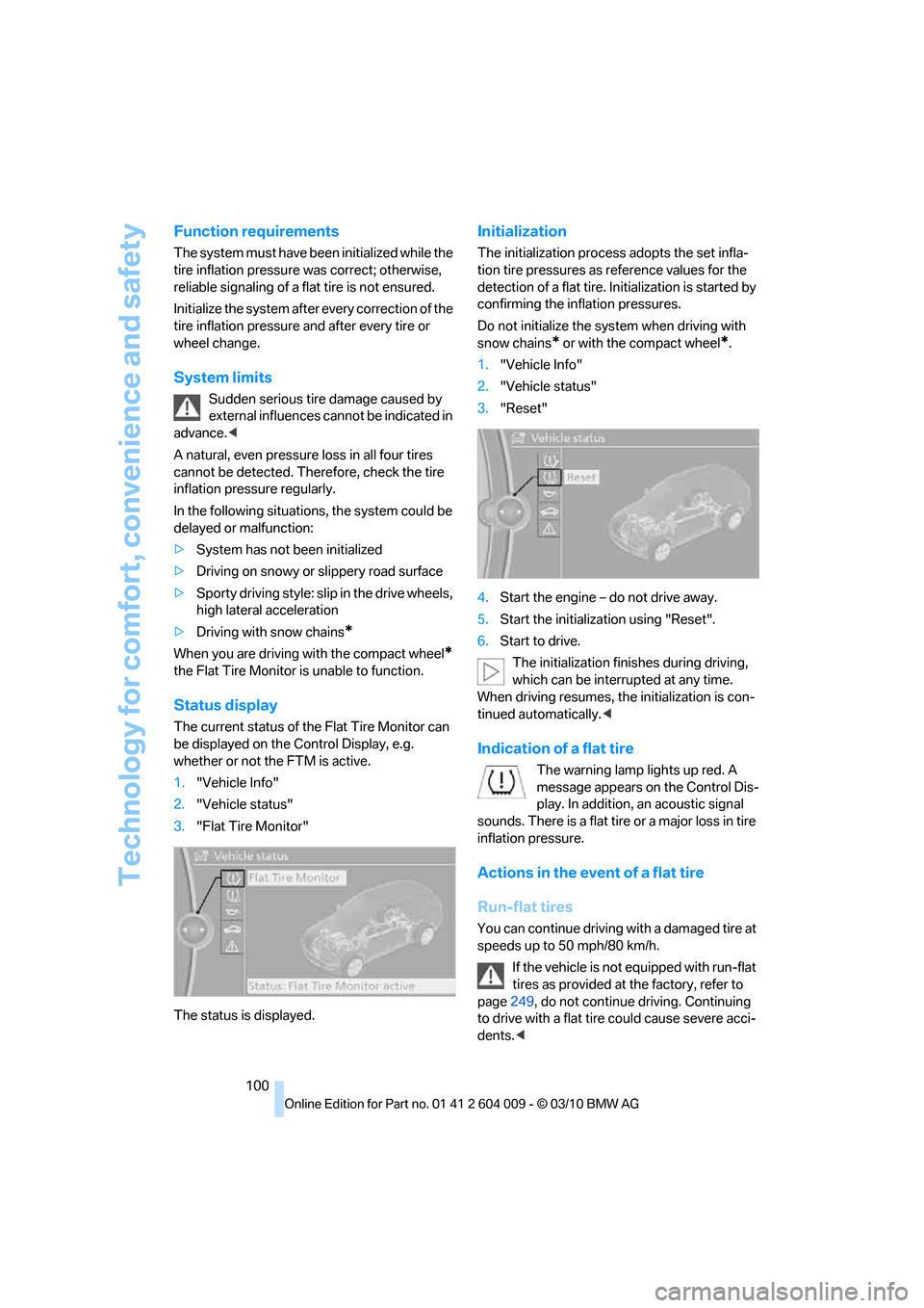
Status display
The current status of the Flat Tire Monitor can
be displayed on the Control Display, e.g.
whether or not the FTM is active.
1."Vehicle Info"
2."Vehicle status"
3."Flat Tire Monitor"
The status is displayed.
Initialization
The initialization process adopts the set infla-
tion tire pressures as reference values for the
detection of a flat tire. Initialization is started by
confirming the inflation pressures.
Do not initialize the system when driving with
snow chains
* or with the compact wheel*.
1."Vehicle Info"
2."Vehicle status"
3."Reset"
4.Start the engine – do not drive away.
5.Start the initialization using "Reset".
6.Start to drive.
The initialization finishes during driving,
which can be interrupted at any time.
When driving resumes, the initialization is con-
tinued automatically.<
Indication of a flat tire
The warning lamp lights up red. A
message appears on the Control Dis-
play. In addition, an acoustic signal
sounds. There is a flat tire or a major loss in tire
inflation pressure.
Actions in the event of a flat tire
Run-flat tires
You can continue driving with a damaged tire at
speeds up to 50 mph/80 km/h.
If the vehicle is not equipped with run-flat
tires as provided at the factory, refer to
page249, do not continue driving. Continuing
to drive with a flat tire could cause severe acci-
dents.<
Page 113 of 312
Controls
111Reference
At a glance
Driving tips
Communications
Navigation
Entertainment
Mobility
Lamps
Parking lamps/low beams
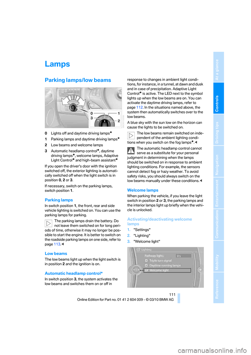
0Lights off and daytime driving lamps*
1Parking lamps and daytime driving lamps*
2Low beams and welcome lamps
3Automatic headlamp control
*, daytime
driving lamps
*, welcome lamps, Adaptive
Light Control
* and high-beam assistant*
If you open the driver's door with the ignition
switched off, the exterior lighting is automati-
cally switched off when the light switch is in
position0, 2 or 3.
If necessary, switch on the parking lamps,
switch position1.
Parking lamps
In switch position1, the front, rear and side
vehicle lighting is switched on. You can use the
parking lamps for parking.
The parking lamps drain the battery. Do
not leave them switched on for long peri-
ods of time, otherwise it may no longer be pos-
sible to start the engine. It is better to switch on
the roadside parking lamps on one side, refer to
page113.<
Low beams
The low beams light up when the light switch is
in position 2 and the ignition is on.
Automatic headlamp control*
In switch position3, the system activates the
low beams and switches them on or off in response to changes in ambient light condi-
tions, for instance, in a tunnel, at dawn and dusk
and in case of precipitation. Adaptive Light
Control
* is active. The LED next to the symbol
lights up when the low beams are on. You can
activate the daytime driving lamps, refer to
page112. In the situations named above, the
system then automatically switches over to the
low beams.
A blue sky with the sun low on the horizon can
cause the lights to be switched on.
The low beams remain switched on inde-
pendent of the ambient lighting condi-
tions when you switch on the fog lamps
*.<
The automatic headlamp control cannot
serve as a substitute for your personal
judgment in determining when the lamps
should be switched on in response to ambient
lighting conditions. For example, the sensors
cannot detect fog or hazy weather. To avoid
safety risks, you should always switch on the
low beams manually under these conditions.<
Welcome lamps
When parking the vehicle, if you leave the light
switch in position2 or3, the parking lamps and
the interior lamps light up briefly when the vehi-
cle is unlocked.
Activating/deactivating welcome
lamps
1."Settings"
2."Lighting"
3."Welcome light"
Page 115 of 312
Controls
113Reference
At a glance
Driving tips
Communications
Navigation
Entertainment
Mobility
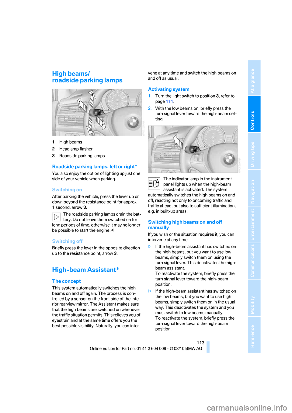
High beams/
roadside parking lamps
1High beams
2Headlamp flasher
3Roadside parking lamps
Roadside parking lamps, left or right*
You also enjoy the option of lighting up just one
side of your vehicle when parking.
Switching on
After parking the vehicle, press the lever up or
down beyond the resistance point for approx.
1 second, arrow3.
The roadside parking lamps drain the bat-
tery. Do not leave them switched on for
long periods of time, otherwise it may no longer
be possible to start the engine.<
Switching off
Briefly press the lever in the opposite direction
up to the resistance point, arrow 3.
High-beam Assistant*
The concept
This system automatically switches the high
beams on and off again. The process is con-
trolled by a sensor on the front side of the inte-
rior rearview mirror. The Assistant makes sure
that the high beams are switched on whenever
the traffic situation permits. This relieves you of
eyestrain and at the same time offers you the
best possible visibility. Naturally, you can inter-vene at any time and switch the high beams on
and off as usual.
Activating system
1.Turn the light switch to position3, refer to
page111.
2.With the low beams on, briefly press the
turn signal lever toward the high-beam set-
ting.
The indicator lamp in the instrument
panel lights up when the high-beam
assistant is activated. The system
automatically switches the high beams on and
off, reacting not only to oncoming traffic and
traffic ahead, but also to sufficient illumination,
e.g. in built-up areas.
Switching high beams on and off
manually
If you wish or the situation requires it, you can
intervene at any time:
>If the high-beam assistant has switched on
the high beams, but you want to use low
beams, simply switch them on using the
turn signal lever. This deactivates the high-
beam assistant.
To reactivate the system, briefly press the
turn signal lever toward the high-beam
position.
>If the high-beam assistant has switched on
the low beams, but you want to use high
beams, simply switch them on in the usual
way. This deactivates the system and you
must switch to low beams manually.
To reactivate the system, briefly press the
turn signal lever toward the high-beam
position.
Page 132 of 312
Practical interior accessories
130
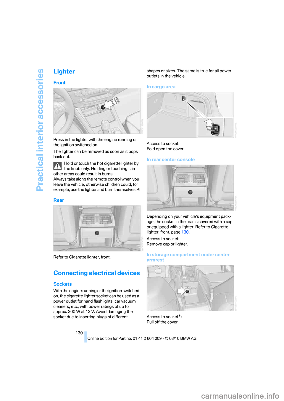
Lighter
Front
Press in the lighter with the engine running or
the ignition switched on.
The lighter can be removed as soon as it pops
back out.
Hold or touch the hot cigarette lighter by
the knob only. Holding or touching it in
other areas could result in burns.
Always take along the remote control when you
leave the vehicle, otherwise children could, for
example, use the lighter and burn themselves.<
Rear
Refer to Cigarette lighter, front.
Connecting electrical devices
Sockets
With the engine running or the ignition switched
on, the cigarette lighter socket can be used as a
power outlet for hand flashlights, car vacuum
cleaners, etc., with power ratings of up to
approx. 200 W at 12 V. Avoid damaging the
socket due to inserting plugs of different shapes or sizes. The same is true for all power
outlets in the vehicle.
In cargo area
Access to socket:
Fold open the cover.
In rear center console
Depending on your vehicle's equipment pack-
age, the socket in the rear is covered with a cap
or equipped with a lighter. Refer to Cigarette
lighter, front, page130.
Access to socket:
Remove cap or lighter.
In storage compartment under center
armrest
Access to socket*:
Pull off the cover.